

Page 1
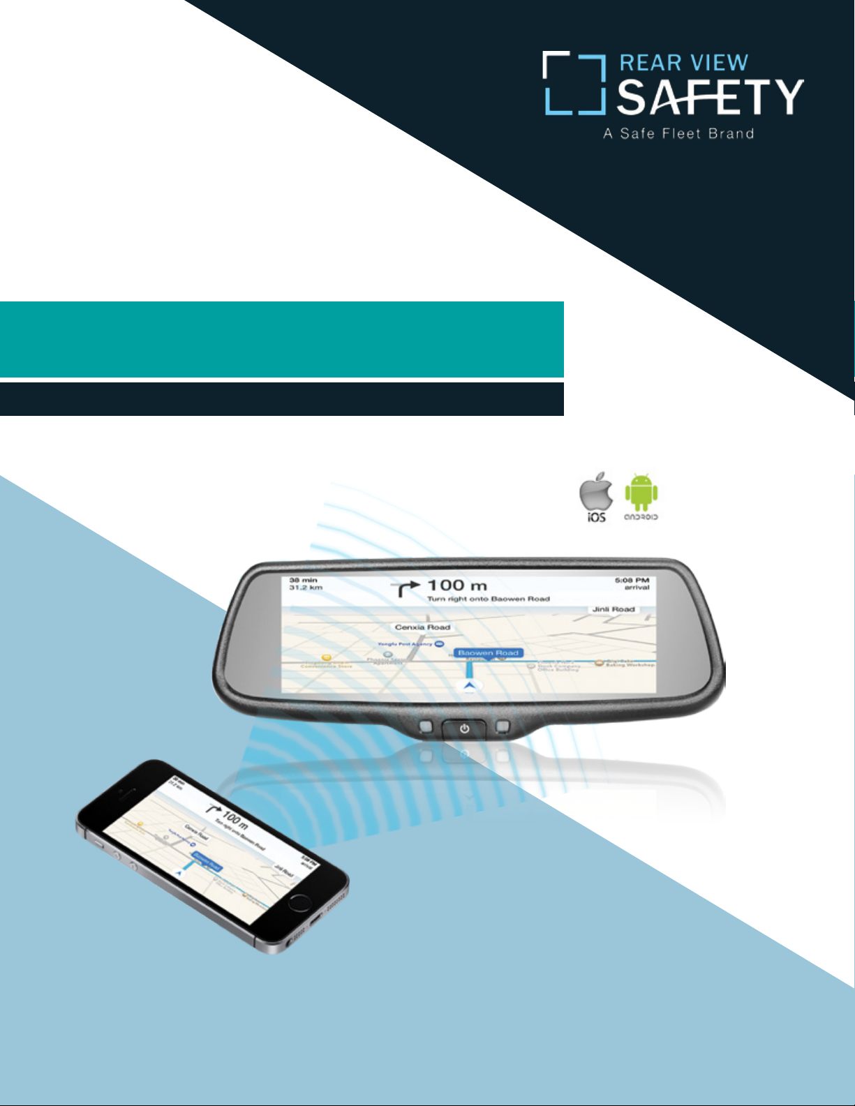
Instruction Manual
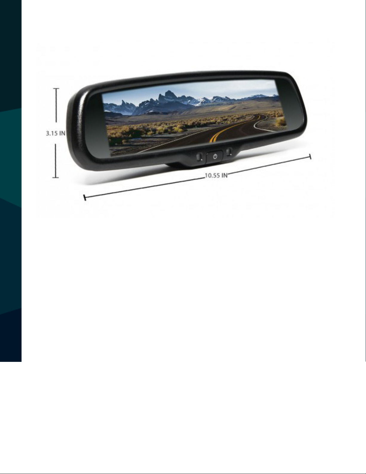
G-Series Rear View Replacement Mirror Monitor
with 7.3” MirrorLink Display
RVS-718-7ML
Rear View Safety, Inc. © 2016
Reverse With Condence ™
1
Page 2
Introduction...............................03
Safety Information..........................04-06
Monitor Information......................... 07-09
Before You Begin .......................10-11
Installation Guide.......................... 12-13
Wiring................................14
Gridlines............................15-16
TABLE OF CONTENTS
2
Remote Control............................ 17
Basic Settings.............................18-19
MirrorLink ............................. 20-22
Display Modes............................23-25
Triggering.............................. 26
Warranty & Disclaimer........................ 27-28
Notes........................ . . . . . 29
Rear View Safety
Page 3

NOTE!
Please read all of the installation instructions
carefully before installing the product. Improper
installation will void manufacturer’s warranty.
Congratulations on purchasing a Rear View Backup
Camera System!
With this manual you will be able to properly install and
operate the unit.
The Backup Camera System is intended to be installed as a
supplement aid to your standard rear view mirror that already exists
in your vehicle. The Backup Camera System should not be used as a
substitute for the standard rear view mirror or for any other mirror
that exists in your vehicle.
In some jurisdictions, it is unlawful for a person to drive a
motor vehicle equipped with a TV viewer or screen located forward of
the back of the driver’s seat or in any location that is visible, directly
or indirectly, to the driver while operating the vehicle.
INTRODUCTION
Reverse With Condence ™
3
Page 4

Please read the entire manual and follow the instructions and
warnings carefully. Failure to do so can cause serious damage and/or
injury, including loss of life. Be sure to obey all applicable local
trac and motor vehicle regulations as it pertains to this product.
Improper installation will void manufacturer’s warranty.
USAGE:
• The Rear View Camera System is
designed to help the driver safely detect people and/or objects
helping to avoid damage or injury.
However, you the driver, must use it
properly. Use of this system is not a
substitute for safe, proper or legal
driving.
• Never back up while looking at the
monitor alone. You should always
damage or injury. Always back up
slowly.
• The Rear View Camera System is
not intended for use during extensive back-up maneuvers or backing
into cross trac or pedestrian walkways.
•Please, always remember, the area
displayed by the Rear View Camera
check behind and around the vehi-
SAFETY INFORMATION
cle when backing up, in the same
way as you would if the vehicle did
not have the Rear View Camera
System. If you back up while looking
only at the monitor, you may cause
4
System is limited. It does not display
the entire panorama that is behind
you.
Rear View Safety
Page 5

INSTALLATION:
• Electric shock or product
malfunction may occur if this
product is installed
incorrectly.
• Use this product within the
voltage range specied. Failure
to do so can cause electronic
shock or product malfunction.
• Take special care when
A short circuit or disconnected wire
may cause a re.
• While installing the Rear View
System be careful with the wire
positioning in order to avoid wire
damage.
• The Rear View System should only
be used when the vehicle is in
reverse.
SAFETY INFORMATION
cleaning the monitor.
• Make sure to rmly ax the
product before use.
• If smoke or a burning smell
is detected, disconnect the
system immediately.
• Where the power cable may
touch a metal case, cover the
• Do not watch movies or
operate the monitor while driving;
as it may cause an
accident.
• Do not install the monitor
where it may obstruct drivers
view or obstruct an air bag
device.
cable with friction tape.
• Dropping the unit may cause
possible mechanical failure.
Reverse With Condence ™
5
Page 6

Before drilling please check that no cable or wiring is on the other side
of the wall. Please clamp all wires securely to reduce the possibility of
being damaged while vehicle is in use. Keep all cables away from hot
or moving parts and electrical noisy components.
We recommend doing a benchmark test before installation
to insure that all components are working properly.
Step 1: Choose the monitor and camera locations.
Step 2: Install all cables in vehicle, when necessary a 0.8 (20mm)
hole should be drilled for passing camera cable through vehicles
walls. Install split grommets where applicable.
Step 3: Once all cables and wiring have been properly routed, perform
a system function test by temporarily connecting the system.
SAFETY INFORMATION
6
Rear View Safety
Page 7
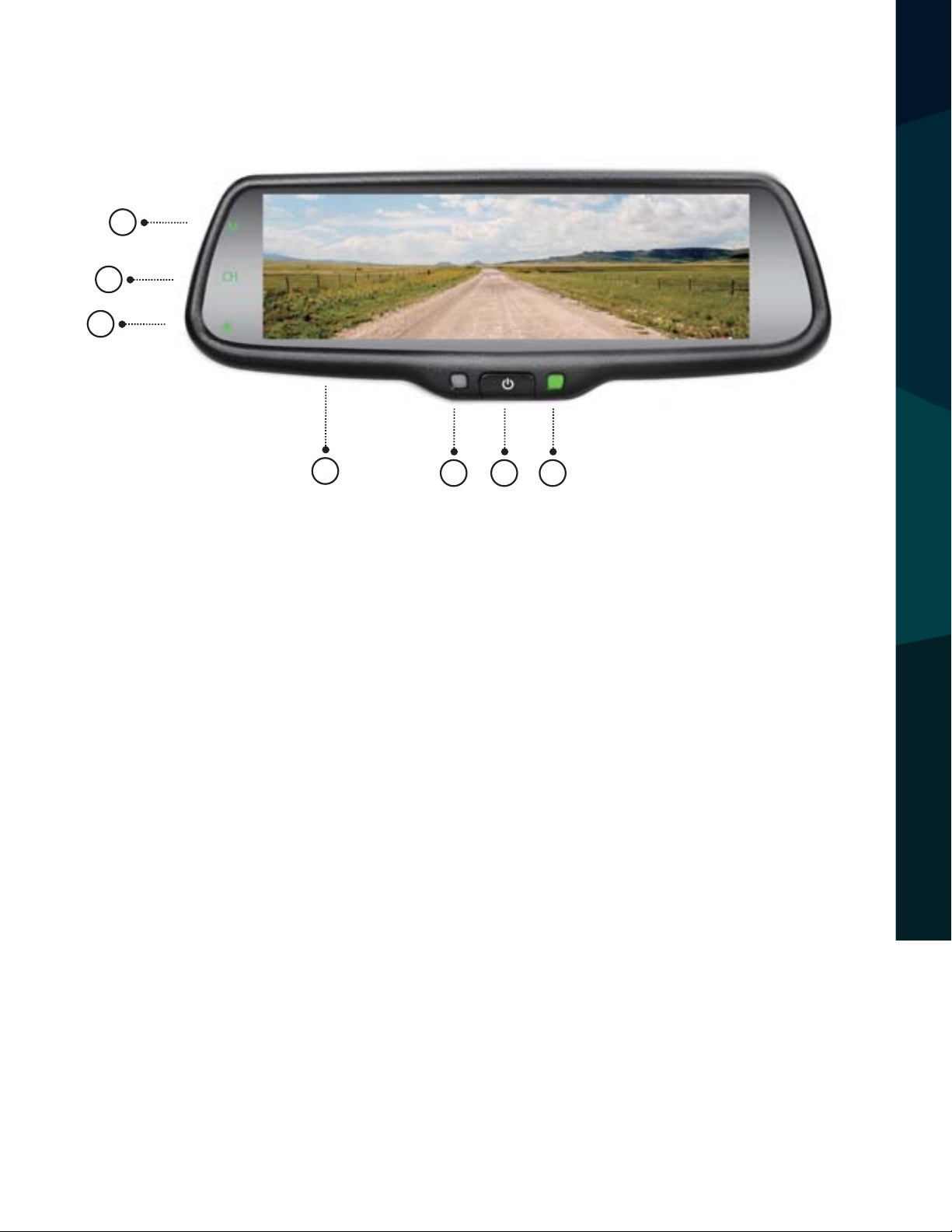
Monitor Buttons
5
6
7
1
2 3 4
1. 7.3” display screen
2. Front light sensor
3. ON/OFF button for screen display. Short press to adjust screen brightness
in reverse mode
4. Power indicator
5. MirrorLink mode switch (M): Use this button to switch mirror link mode
(Miracast Mode for Android and DNLA Mode for iOS)
6. Display switch (CH): Use this button to switch between display modes.
MONITOR INFORMATION
Display modes include full side/rear camera displays, a full mirrorlink
display, and multiple dual displays
7. Color Adjustment: Short press to adjust color. Options are standard, bright,
beautiful, and soft
Reverse With Condence ™
7
Page 8
8
10
11
12
13
14
15
10
MONITOR INFORMATION
8
9
8
Rear View Safety
Page 9

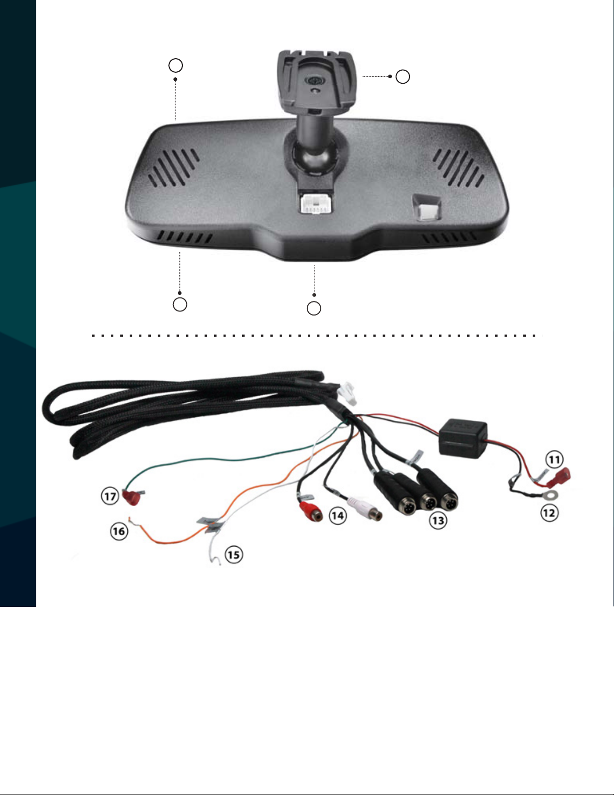
8. Speaker
9. Connector
10. Special Bracket
11. Red To ACC+
12. Black To GND
13. 5 Pin Camera Connectors
14. Audio Cables
15. Trigger Line 1
16. Trigger Line 2
17. Rear Signal
MONITOR INFORMATION
Reverse With Condence ™
9
Page 10

Replacement Monitor
The mirror monitor replaces the existing car mirror. Carefully remove
the mirror o the “pin”. Slide the replacement mirror on to the pin and
secure it with the screw provided (already in the screw hole).Dierent cars have dierent brackets, depending on your vehicle make and
manufacturer. There are many methods to remove the original rearview mirror, however, please don’t force the mirror o the bracket.
The manufacturer will not be responsible for damage caused to your
car by an improper mirror installation.
Camera & Cable
Be sure to position the cable properly. The aviation camera cable uses
aircraft grade connectors which means the camera cable can be exposed to all weather elements. Do not run the cable over sharp edges,
do not kink the cable, and keep away from HOT and rotating parts.
Fasten all cables and secure all excess cable. Connect camera to the
camera extension cable running inside the vehicle.
BEFORE YOU BEGIN
10
Rear View Safety
Page 11

Wiring
After connecting the camera to the “camera cable” the camera should
be plugged into AV2. Connect the RED 12V power wire to an
ignition power source and the BLACK 12V ground wire to a chassis
ground. The GREEN wire is the REVERSE trigger wire. Connect this wire
to the vehicle’s backup light circuit to activate the rear-view image
whenever the vehicle shifts into reverse. To connect a second camera,
connect it to AV1. It can be turned on by pressing the power button on
the monitor.
Precautions for use of Mirror Monitor
I. The Mirror Monitor is made of glass. Do not subject it to a
mechanical shock by dropping it from a high place, etc.
II. Do not apply excessive force to the monitor surface or the
adjoining areas since this may cause the color tone to vary.
III. Only clean with a soft dry cloth and/or Windex.
IV. Do not attempt to disassemble the mirror monitor.
Safety
• Before drilling, be sure no cable or wire is on the other side.
• Feed as much cable as possible into vehicle & clamp securely.
BEFORE YOU BEGIN
This reduces the possibility of cable being hooked or snagged.
Reverse With Condence ™
11
Page 12

Installation and Wiring
Dierent cars have dierent brackets/bases. It depends on your vehicle
maker/manufacturer. There are many ways to remove the original rear
view mirror. Do not force the mirror o the bracket. The manufacturer
will not be responsible for any damage caused to your car by improper
mirror installation.
INSTALLATION GUIDE
12
Rear View Safety
Page 13

2.2 Special bracket
Bracket Type
If the mirror monitor doesn’t t in your vehicle, please contact us. We
INSTALLATION GUIDE
have many dierent kinds of brackets and adaptors.
Reverse With Condence ™
13
Page 14

How to Wire
2.3 How to wire
The advisable installaƟon
posiƟon for camera
LeŌ video
By connecƟng the green line, the reversing signal is input to the rear view mirror and
reversing video can automaƟcally display on the wide 7.3 inch LCD monitor.
3M
Power harness
FUSE
BOX
Black to GND
Red to ACC +12V
Black to GND
Red to ACC +12V
Black to GND
Red to ACC +12V
Back up video
LeŌ video
Green
Back car signal
Trigger line 1
Purple
Back up video
Right video
LeŌ video
3M
Power harness
Audio
Cables
5 Pin Camera Connector
Green
White
Orange
FUSE
BOX
5 Pin Camera Connector
5 Pin Camera
Connector
Rear signal
Trigger line 1
Trigger line 2
Red to ACC +12V
Black to GND
Black to GND
Red to ACC +12V
Back up
camera
Black to GND
Red to ACC +12V
Le
camera
WIRING
14
Rear View Safety
Page 15

Chapter three: Adjustable Guideline
Generally, to help drivers esmate the distance from obstacles, there are three lines for
reference -red, yellow and green. Those three lines are displayed on the monitor when car is
reversing. The green line is 3m from the back of car and the yellow line is 2m. The distant red
line is 1m from the backside of car while the closed red line is 0.4m. Both reference lines on
the le and right should leave 0.2m space from the car.
3.1 About guide line
3.3 How to adjust the guide line
Note: keep the remote control 05.m-1.0m from rear view mirror when you use the remote
to adjust the parking lines.
According to the site of standard reference line, we can put reference objects such as desks
in the back side of the car. Compared with the marked reference objects, we can adjust the
sites and angles of two guide lines are displayed on the monitor. You will get the accurate
and safety guide lines once it coincides with the reference objects.
Press seng buon to enter “guide line adjustment” mode. The system is defaulted to
adjust le guide line rst. Press the buon again to switch to adjust the right guide line.
The up , down , le and right buons are to adjust the corresponding locaon
of guide lines. The clockwise rotaon and contra rotang buons are to adjust the
angles of guide lines. It is easy to operate and calibrate. Aer nishing calibraon, switch the
reverse gear to save the informaon.
Adjustable Grid Lines
Generally, to help drivers estimate the distance from obstacles, there
are three lines for reference -red, yellow and green. These three lines
are displayed on the monitor when car is reversing. The green line is 3m
from the back of car and the yellow line is 2m. The distant red line is 1m
from the back of car while the closed red line is 0.4m. Both reference
lines on the left and right should leave 0.2m space from the car.
20CM20CM
The accuracy of the grid lines can vary based on how you angle your camera. Adjust the grid lines to compensate for inaccuracies.
GRIDLINES
Reverse With Condence ™
15
Page 16

3.3 How to adjust the guide line
Note: keep the remote control 05.m-1.0m from rear view mirror when you use the remote
to adjust the parking lines.
According to the site of standard reference line, we can put reference objects such as desks
in the back side of the car. Compared with the marked reference objects, we can adjust the
sites and angles of two guide lines are displayed on the monitor. You will get the accurate
and safety guide lines once it coincides with the reference objects.
Press seng buon to enter “guide line adjustment” mode. The system is defaulted to
adjust le guide line rst. Press the buon again to switch to adjust the right guide line.
The up , down , le and right buons are to adjust the corresponding locaon
of guide lines. The clockwise rotaon and contra rotang buons are to adjust the
angles of guide lines. It is easy to operate and calibrate. Aer nishing calibraon, switch the
reverse gear to save the informaon.
Long press the “Settings” (middle) button on the remote to enter grid
line adjustment mode. Press the “Settings” button again to toggle between left/right grid lines. Use the “UP/DOWN/LEFT/RIGHT” buttons to
adjust grid line location, and the rotation buttons to adjust grid line
angle.
Right posiƟon
Wrong posiƟon
RL
GRIDLINES
Remote control Move the guide line Rotate the guide line
Display on the monitor
Press the buƩon to choose L or R adjustable guide line
Up
Le
Right
Down
Clockwise
An-clockwise
16
Rear View Safety
Page 17

Chapter Four: Menu Seƫng
4.1 Remote control
The menu only can be set by remote control, and kindly check its deniƟon as below.
Remote Control
The remote must be used to change menu settings.
Enter picture menu
Menu parameter decrease
Guide line up
Menu parameter increase
Enter guide line adjustment
Guide line clockwise
Guide line anƟ-clockwise
Guide line leŌ
Guide line right
Guide line down
Press to reset all
menu and parameters
How To Use Menu
Short press “MENU” to enter “PICTURE.” Here you may choose “BRIGHT-
REMOTE CONTROL
NESS”, “COLOR”, “CONTRAST”, “SCALE”, “START LOGO”, or “PRESET.”
Use the “UP/DOWN” buttons to change settings.
Reverse With Condence ™
17
Page 18

Enter picture menu
Guide line clockwise
Menu parameter decrease
Menu parameter increase
Guide line up
Guide line leŌ
Guide line anƟ-clockwise
Guide line right
Guide line down
Press to reset all
menu and parameters
4.2.3 CONTRAST ADJUSTMENT
The defaulted seƫng is 50, ranging from 0 to 100, and only CVBS signal
can work.
It's only for the model with guide lines, and no such seƫng for those without such funcƟon.
ON is defaulted seƫng, and you can manually set it to OFF.
4.2.4 SCALE ADJUSTMENT
Brightness Level
Brightness/color/contrast levels range from 0 to 100. The default is 50.
Color Level
BASIC SETTINGS
Contrast Level
18
Rear View Safety
Page 19

Scale Adjustment
Scale function will only work with gridlines. Choose “ON/OFF.”
Default is “ON.”
Start Logo On/O
Choose “ON/OFF.” Default is “ON.”
Preset Menu
Save basic settings. Choose “ON/OFF.” Default is “OFF.”
Volume Adjustment
Volume adjustments range from 0 to 100. The default is 80.
BASIC SETTINGS
Reverse With Condence ™
19
Page 20

MirrorLink
Use mirrorlink to display your mobile phone on your rear view mirror monitor through WiFi and programs such as DLNA, Miracast and Airplay.
Note: Bluetooth must be off to use mirrorlink.
How to Connect (Android)
Press the “M” button on your monitor, switch wireless mode to “Android
Device”, and open the WiFi on phone. Search for mirror connection as
shown on next page.
“M”buƩon
MIRRORLINK
20
Rear View Safety
Page 21

“M”buƩon
1: Click the “M” buƩon on TP buƩon, switch the wireless mode to iOS mode.
2: Using iPhone search Wi-Fi (Wi-Fi name is displayed on the screen and shown as below),
then enter the default password: 12345678. AŌer nishing Wi-Fi connecƟon, bring up the
shortcut menu, click on the AirPlay funcƟon, select the device name, and open the mirroring.
5.1.2 How to connect with iPhone
tap here
tap here
tap here
After the mirror link is connected, press the “CH” button to toggle between
AŌer nishing the connecƟon, then the phone screen projected onto the rear view mirror,
you can press “CH” on TP buƩon to choose “double mobile dual mode” or “single-screen
single and dual display modes.
mode”.
MIRRORLINK
Reverse With Condence ™
21
Page 22

2: Using iPhone search Wi-Fi (Wi-Fi name is displayed on the screen and shown as below),
then enter the default password: 12345678. A
shortcut menu, click on the AirPlay func
5.1.2 How to connect with iPhone
How to Connect with iPhone
1: Press the “M” button to switch the wireless mode to “iOS Device.”
“M”buƩon
2: Search for the WiFi connection as shown below. Default password is
12345678. After connecting, turn AirPlay on and turn on mirroring as
shown below.
Wi-Fi name
Ɵon, select the device name, and open the mirroring.
Ōer nishing Wi-Fi connecƟon, bring up the
Tap here
MIRROR LINK
Turn on it
22
Tap here
Rear View Safety
Page 23

AŌer nishing the connecƟon, then the phone screen projected to the rear view mirror, you
can press “CH” on TP buƩon to choose “ double mobile dual mode” or “single-screen mode”.
5.2.2 Full VIDEO1 screen display
5.2.3 Full MOBILE screen display
Channel Switching
After the mirror link is connected, press the “CH” button to toggle between
single and dual display modes.
Full Backup Camera Display
5.2 Channel switching
Press the “CH” buƩon on the screen to switch display among CAMERA, VIDEO1, MOBILE,
VIDEO1+MOBILE, MOBILE+VIDEO1, CAMERA+MOBILE, and MOBILE+CAMERA.
5.2.1 Full CAMERA screen display
DISPLAY MODES
Reverse With Condence ™
23
Page 24

5.2.2 Full VIDEO1 screen display
Full Side Camera Display
Full MirrorLink Display
5.2.3 Full MOBILE screen display
DISPLAY MODES
24
Rear View Safety
Page 25

Side Camera/MirrorLink Dual Display
5.2.4 VIDEO1 and MOBILE display simultaneously
5.2.5 CAMERA and MOBILE display simultaneously
Please note:
1. Both Reversing mode and non-reversing mode have seven states: mirrorlink,
Video+mirrorlink, Mirrorlink+video, camera+mirrorlink, Mirrorlink+camera, video full screen,
camera full screen.
2. Power on each me, the screen automacally keep the last state before shutdown, which
has eight styles, seven of which are as above 1, addionally an o-screen state, Totally eight
states.
3. There are three modes of operaon can trigger video;
1) The rst grade is +12V BACKUP LIGHT: You can adjust the seven states when there is signal
of triggering reversing thought touching CH buon. The nal state will be remembered aer
powering o, and the nal state be shown automacally when trigger BACKUP LIGHT
next me;
2) The second grade is +12V VIDEO CONTROL-- Video channel triggered line, which connect
turn light or brake light in a general way. Mirror will automacally switch to full screen mode
of VIDEO when the trigger signal appears; while it will automacally switch to previous state
when the trigger signal disappears aer 3 seconds, in VIDEO trigger state: the only brightness
buon of TP buon can work, while buon of M and CH don't work.
4. When the camera and mobile show at the same me, guide line can't be displayed.
Backup Camera/MirrorLink Dual Display
DISPLAY MODES
Reverse With Condence ™
25
Page 26

Please Note
1. This system has multiple display modes, including full side/rear camera displays, a full mirrorlink display, and multiple dual displays
2. When turned on, the screen will automatically show the last display mode
viewed
Triggering Video
1. Reversing your vehicle will trigger your rear camera.
2. The mirror will automatically switch to the full camera display when the
brake or turn signals are used.
3. When a camera/mirrorlink dual display is shown, gridlines will not be displayed.
TRIGGERING
26
Rear View Safety
Page 27

ONE YEAR WARRANTY
REAR VIEW SAFETY, INC. WARRANTS THIS PRODUCT AGAINST MATERIAL DEFECTS FOR A
PERIOD OF ONE YEAR FROM DATE OF PURCHASE. WE RESERVE THE RIGHT TO REPAIR OR
REPLACE ANY SUCH DEFECTIVE UNIT AT OUR SOLE DISCRETION. REAR VIEW SAFETY, INC.
IS NOT RESPONSIBLE FOR A DEFECT IN THE SYSTEM AS A RESULT OF MISUSE, IMPROPER
INSTALLATION, DAMAGE OR MISHANDLING OF THE ELECTRONIC COMPONENTS. REAR VIEW
SAFETY, INC. IS NOT RESPONSIBLE FOR CONSEQUENTIAL DAMAGES OF ANY KIND.
THIS WARRANTY IS VOID IF: DEFECTS IN MATERIALS OR WORKMANSHIP OR DAMAGES
RESULT FROM REPAIRS OR ALTERATIONS WHICH HAVE BEEN MADE OR ATTEMPTED BY
OTHERS OR THE UNAUTHORIZED USE OF NONCONFORMING PARTS; THE DAMAGE IS DUE
TO NORMAL WEAR AND TEAR, THIS DAMAGE IS DUE TO ABUSE, IMPROPER MAINTENANCE,
NEGLECT OR ACCIDENT; OR THE DAMAGE IS DUE TO USE OF THE REAR VIEW SAFETY, INC.
SYSTEM AFTER PARTIAL FAILURE OR USE WITH IMPROPER ACCESSORIES.
WARRANTY PERFORMANCE
DURING THE ABOVE WARRANTY PERIOD, SHOULD YOUR REAR VIEW SAFETY PRODUCT
EXHIBIT A DEFECT IN MATERIAL OR WORKMANSHIP, SUCH DEFECT WILL BE REPAIRED WHEN
THE COMPLETE REAR VIEW SAFETY, INC. PRODUCT IS RETURNED, POSTAGE PREPAID AND
INSURED, TO REAR VIEW SAFETY, INC. OTHER THAN THE POSTAGE AND INSURANCE
REQUIREMENT, NO CHARGE WILL BE MADE FOR REPAIRS COVERED BY THIS WARRANTY.
WARRANTY DISCLAIMERS
NO WARRANTY, ORAL OR WRITTEN, EXPRESSED OR IMPLIED, OTHER THE ABOVE WARRANTY
IS MADE WITH REGARD TO THIS REAR VIEW SAFETY, INC. REAR VIEW SAFETY, INC. DISCLAIMS
ANY IMPLIED WARRANTY OR MERCHANTABILITY OR FITNESS FOR A PARTICULAR USE OR
PURPOSE AND ALL OTHER WARRANTIES IN NO EVENT SHALL REAR VIEW SAFETY. INC.
LIABLE FOR ANY INCIDENTAL, SPECIAL, CONSEQUENTIAL, OR PUNITIVE DAMAGES OR FOR
ANY COSTS, ATTORNEY FEES, EXPENSES, LOSSES OR DELAYS ALLEGED TO BE AS A
WARRANTY
CONSEQUENCE OF ANY DAMAGE TO, FAILURE OF, OR DEFECT IN ANY PRODUCT INCLUDING,
BUT NOT LIMITED TO, ANY CLAIMS FOR LOSS OF PROFITS.
Reverse With Condence ™
27
Page 28

DISCLAIMER
REAR VIEW SAFETY AND/OR ITS AFFILIATES DOES NOT GUARANTEE OR PROMISE THAT THE
USER OF OUR SYSTEMS WILL NOT BE IN/PART OF AN ACCIDENT OR OTHERWISE NOT COLLIDE
WITH AN OBJECT AND/OR PERSON. OUR SYSTEMS ARE NOT A SUBSTITUTE FOR CAREFUL
AND CAUTIOUS DRIVING OR FOR THE CONSISTENT ADHERENCE TO ALL APPLICABLE TRAFFIC
LAWS AND MOTOR VEHICLE SAFETY REGULATIONS. THE REAR VIEW SAFETY PRODUCTS ARE
NOT A SUBSTITUTE FOR REARVIEW MIRRORS OR FOR ANY OTHER MOTOR VEHICLE
EQUIPMENT MANDATED BY LAW. OUR CAMERA SYSTEMS HAVE A LIMITED FIELD OF VISION
AND DO NOT PROVIDE A COMPREHENSIVE VIEW OF THE REAR OR SIDE AREA OF THE VEHICLE.
ALWAYS MAKE SURE TO LOOK AROUND YOUR VEHICLE AND USE YOUR MIRRORS TO CONFIRM
REARWARD CLEARANCE AND THAT YOUR VEHICLE CAN MANEUVER SAFELY. REAR VIEW
SAFETY AND/OR ITS AFFILIATES SHALL HAVE NO RESPONSIBILITY OR LIABILITY
FOR DAMAGE AND/OR INJURY RESULTING FROM ACCIDENTS OCCURRING WITH VEHICLES
HAVING SOME OF REAR VIEW SAFETY PRODUCTS INSTALLED AND REAR VIEW SAFETY AND/
OR ITS AFFILIATES, THE MANUFACTURER, DISTRIBUTOR AND SELLER SHALL NOT BE LIABLE
FOR ANY INJURY, LOSS OR DAMAGE, INCIDENTAL OR CONSEQUENTIAL, ARISING OUT OF THE
USE OR INTENDED USE OF THE PRODUCT. IN NO EVENT SHALL REAR VIEW SAFETY AND/OR
ITS AFFILIATES HAVE ANY LIABILITY FOR ANY LOSSES WHETHER DIRECT OR INDIRECT, IN
CONTRACT, TORT OR OTHERWISE INCURRED IN CONNECTION WITH THE SYSTEMS,
INCLUDING BUT NOT LIMITED TO DAMAGED PROPERTY, PERSONAL INJURY AND/OR LOSS OF
RESPONSIBILITY FOR ANY DECISION, ACTION OR INACTION TAKEN BY ANY PERSON IN
RELIANCE ON REAR VIEW SAFETY SYSTEMS, OR FOR ANY DELAYS, INACCURACIES AND/OR
DISCLAIMER
LIFE. NEITHER SHALL REAR VIEW SAFETY AND/OR ITS AFFILIATES HAVE ANY
ERRORS IN CONNECTION WITH OUR SYSTEMS FUNCTIONS.
28
Rear View Safety
Page 29

Notes
Reverse With Condence ™
NOTES
29
Page 30

If you have any questions
about this product, contact:
Rear View Safety, Inc.
1797 Atlantic Avenue
Brooklyn, NY 11233
800.764.1028
IN NO EVENT SHALL SELLER OR MANUFACTURER BE
30
LIABLE FOR ANY DIRECT OR CONSEQUENTIAL DAMAGES OF
ANY NATURE, OR LOSSES OR EXPENSES RESULTING FROM
ANY DEFECTIVE PRODUCT OR THE USE OF ANY PRODUCT.
Better Cameras. Better Service.
IT’S OUR GUARANTEE.
Rear View Safety
 Loading...