

Page 1

12-Oct-2017 17:27
Date:
RVS-96D Installation and
Setup Guide
COPYRIGHT © 2017 Rear View Safety
Page 2

Table of Contents
Introduction . . . . . . . . . . . . . . . . . . . . . . . . . . . . . . . . . . . . . . . . . . . . . . . . . . . . . . . 5
Front Panel . . . . . . . . . . . . . . . . . . . . . . . . . . . . . . . . . . . . . . . . . . . . . . . . . . . . . . . . . . . . . . . . . . . 8
Controls and Indicators . . . . . . . . . . . . . . . . . . . . . . . . . . . . . . . . . . . . . . . . . . . . . . . . . . . . . . . . . . 9
Back Panel . . . . . . . . . . . . . . . . . . . . . . . . . . . . . . . . . . . . . . . . . . . . . . . . . . . . . . . . . . . . . . . . . . 10
SD Compartment . . . . . . . . . . . . . . . . . . . . . . . . . . . . . . . . . . . . . . . . . . . . . . . . . . . . . . . . . . . . . 11
Right Side - USB Port . . . . . . . . . . . . . . . . . . . . . . . . . . . . . . . . . . . . . . . . . . . . . . . . . . . . . . . . . 12
Bottom Panel Connectors . . . . . . . . . . . . . . . . . . . . . . . . . . . . . . . . . . . . . . . . . . . . . . . . . . . . . . 13
Camera Connection Cable . . . . . . . . . . . . . . . . . . . . . . . . . . . . . . . . . . . . . . . . . . . . . . . . . . . . . 14
Power and Camera-Trigger Cable . . . . . . . . . . . . . . . . . . . . . . . . . . . . . . . . . . . . . . . . . . . . . . . 15
Connections Overview . . . . . . . . . . . . . . . . . . . . . . . . . . . . . . . . . . . . . . . . . . . . . . . . . . . . . . . . 16
Camera Connection . . . . . . . . . . . . . . . . . . . . . . . . . . . . . . . . . . . . . . . . . . . . . . . . . . . . . . . . . . . 16
Camera Trigger Connections . . . . . . . . . . . . . . . . . . . . . . . . . . . . . . . . . . . . . . . . . . . . . . . . . . . 17
Power Connection . . . . . . . . . . . . . . . . . . . . . . . . . . . . . . . . . . . . . . . . . . . . . . . . . . . . . . . . . . . . 17
Residential Front-Load (Curotto-Can) . . . . . . . . . . . . . . . . . . . . . . . . . . . . . . . . . . . . . . . . . . . . 19
Commercial Front-Load . . . . . . . . . . . . . . . . . . . . . . . . . . . . . . . . . . . . . . . . . . . . . . . . . . . . . . . 19
Roll-off and Rear-Load . . . . . . . . . . . . . . . . . . . . . . . . . . . . . . . . . . . . . . . . . . . . . . . . . . . . . . . . 20
Residential Side-Load . . . . . . . . . . . . . . . . . . . . . . . . . . . . . . . . . . . . . . . . . . . . . . . . . . . . . . . . . 20
RVS-96D Kit Contents . . . . . . . . . . . . . . . . . . . . . . . . . . . . . . . . . . . . . . . . . . . . . . . 7
Making RVS-96D Connections . . . . . . . . . . . . . . . . . . . . . . . . . . . . . . . . . . . . . .. . 15
Recommended RVS-96D Camera Locations and Settings . . . . . . . . . . . . . . . . . . 17
RVS-96D Electrical Tapping Points Reference Guide . . . . . . . . . . . . . . . . . . . . . . 20
Page 3

Quick Links - Sample Vehicle Installations . . . . . . . . . . . . . . . . . . . . . . . . . . . . . . . . . . . . . . . . 22
Electrical Requirements . . . . . . . . . . . . . . . . . . . . . . . . . . . . . . . . . . . . . . . . . . . . . . . . . . . . . . . 22
12v . . . . . . . . . . . . . . . . . . . . . . . . . . . . . . . . . . . . . . . . . . . . . . . . . . . . . . . . . . . . . . . . . . . . . . . . . 22
Ground . . . . . . . . . . . . . . . . . . . . . . . . . . . . . . . . . . . . . . . . . . . . . . . . . . . . . . . . . . . . . . . . . . . . . . 22
Reverse & Brake . . . . . . . . . . . . . . . . . . . . . . . . . . . . . . . . . . . . . . . . . . . . . . . . . . . . . . . . . . . . . . 22
Mack - MRU . . . . . . . . . . . . . . . . . . . . . . . . . . . . . . . . . . . . . . . . . . . . . . . . . . . . . . . . . . . . . . . . . . 23
Mack - MR . . . . . . . . . . . . . . . . . . . . . . . . . . . . . . . . . . . . . . . . . . . . . . . . . . . . . . . . . . . . . . . . . . . 24
MACK - LEU600 . . . . . . . . . . . . . . . . . . . . . . . . . . . . . . . . . . . . . . . . . . . . . . . . . . . . . . . . . . . . . . 25
Mack - CT713 . . . . . . . . . . . . . . . . . . . . . . . . . . . . . . . . . . . . . . . . . . . . . . . . . . . . . . . . . . . . . . . . 26
Autocar . . . . . . . . . . . . . . . . . . . . . . . . . . . . . . . . . . . . . . . . . . . . . . . . . . . . . . . . . . . . . . . . . . . . . 27
12V & Ground (Configuration 1) . . . . . . . . . . . . . . . . . . . . . . . . . . . . . . . . . . . . . . . . . . . . . . . . . . 27
12V & Ground (Configuration 2) . . . . . . . . . . . . . . . . . . . . . . . . . . . . . . . . . . . . . . . . . . . . . . . . . . 27
12V & Ground (Configuration 3) . . . . . . . . . . . . . . . . . . . . . . . . . . . . . . . . . . . . . . . . . . . . . . . . . . 29
Brake and Reverse (Configuration 1) . . . . . . . . . . . . . . . . . . . . . . . . . . . . . . . . . . . . . . . . . . . . . . 30
Brake and Reverse (Configuration 2) . . . . . . . . . . . . . . . . . . . . . . . . . . . . . . . . . . . . . . . . . . . . . . 31
Peterbilt . . . . . . . . . . . . . . . . . . . . . . . . . . . . . . . . . . . . . . . . . . . . . . . . . . . . . . . . . . . . . . . . . . . . . 32
International - 7600 . . . . . . . . . . . . . . . . . . . . . . . . . . . . . . . . . . . . . . . . . . . . . . . . . . . . . . . . . . . 33
Freightliner - M2 12yd Minimax 2014 . . . . . . . . . . . . . . . . . . . . . . . . . . . . . . . . . . . . . . . . . . . . . 33
CCC . . . . . . . . . . . . . . . . . . . . . . . . . . . . . . . . . . . . . . . . . . . . . . . . . . . . . . . . . . . . . . . . . . . . . . . . 35
Sterling - Condor . . . . . . . . . . . . . . . . . . . . . . . . . . . . . . . . . . . . . . . . . . . . . . . . . . . . . . . . . . . . . 36
American - LaFrance . . . . . . . . . . . . . . . . . . . . . . . . . . . . . . . . . . . . . . . . . . . . . . . . . . . . . . . . . . 37
Lift signal tap points . . . . . . . . . . . . . . . . . . . . . . . . . . . . . . . . . . . . . . . . . . . . . . . . . . . . . . . . . . 38
Peterbilt . . . . . . . . . . . . . . . . . . . . . . . . . . . . . . . . . . . . . . . . . . . . . . . . . . . . . . . . . . . . . . . . . . . . . 38
Labrie Arms . . . . . . . . . . . . . . . . . . . . . . . . . . . . . . . . . . . . . . . . . . . . . . . . . . . . . . . . . . . . . . . . . . 38
Zero Radius – Autocar 2014 . . . . . . . . . . . . . . . . . . . . . . . . . . . . . . . . . . . . . . . . . . . . . . . . . . . . . 38
Accessing the System Configuration Menus . . . . . . . . . . . . . . . . . . . . . . . . . . . . . . . . . . . . . . 39
Setting Date/Time and Operating Language . . . . . . . . . . . . . . . . . . . . . . . . . . . . . . . . . . . . . . . 41
Setting Video Parameters . . . . . . . . . . . . . . . . . . . . . . . . . . . . . . . . . . . . . . . . . . . . . . . . . . . . . . 43
Copying Your Video Settings to Other Channels . . . . . . . . . . . . . . . . . . . . . . . . . . . . . . . . . . . . . . 46
RVS-96D System Configuration . . . . . . . . . . . . . . . . . . . . . . . . . . . . . . . . . . . . . . 38
Page 4

Specifying Record Settings . . . . . . . . . . . . . . . . . . . . . . . . . . . . . . . . . . . . . . . . . . . . . . . . . . . . 46
Copying Your Record Settings to Other Channels . . . . . . . . . . . . . . . . . . . . . . . . . . . . . . . . . . . . 49
Specifying Alarm Settings . . . . . . . . . . . . . . . . . . . . . . . . . . . . . . . . . . . . . . . . . . . . . . . . . . . . . 49
Copying Your Alarm Settings to Other Channels . . . . . . . . . . . . . . . . . . . . . . . . . . . . . . . . . . . . . . 51
Specifying Motion Detection Settings . . . . . . . . . . . . . . . . . . . . . . . . . . . . . . . . . . . . . . . . . . . . 51
Copying Your Motion Detection Settings to Other Channels . . . . . . . . . . . . . . . . . . . . . . . . . . . . . 54
Specifying Vehicle Information . . . . . . . . . . . . . . . . . . . . . . . . . . . . . . . . . . . . . . . . . . . . . . . . . 54
Specifying G-Sensor Settings . . . . . . . . . . . . . . . . . . . . . . . . . . . . . . . . . . . . . . . . . . . . . . . . . . 56
System Setup Menus . . . . . . . . . . . . . . . . . . . . . . . . . . . . . . . . . . . . . . . . . . . . . . . 57
Main Menu . . . . . . . . . . . . . . . . . . . . . . . . . . . . . . . . . . . . . . . . . . . . . . . . . . . . . . . . . . . . . . . . . . 59
System Settings . . . . . . . . . . . . . . . . . . . . . . . . . . . . . . . . . . . . . . . . . . . . . . . . . . . . . . . . . . . . . . 59
General Settings . . . . . . . . . . . . . . . . . . . . . . . . . . . . . . . . . . . . . . . . . . . . . . . . . . . . . . . . . . . . . . 60
Video Settings . . . . . . . . . . . . . . . . . . . . . . . . . . . . . . . . . . . . . . . . . . . . . . . . . . . . . . . . . . . . . . . . 60
Record Settings . . . . . . . . . . . . . . . . . . . . . . . . . . . . . . . . . . . . . . . . . . . . . . . . . . . . . . . . . . . . . . . 61
Alarm Control . . . . . . . . . . . . . . . . . . . . . . . . . . . . . . . . . . . . . . . . . . . . . . . . . . . . . . . . . . . . . . . . . 61
Motion Detection . . . . . . . . . . . . . . . . . . . . . . . . . . . . . . . . . . . . . . . . . . . . . . . . . . . . . . . . . . . . . . 62
Monitor Display . . . . . . . . . . . . . . . . . . . . . . . . . . . . . . . . . . . . . . . . . . . . . . . . . . . . . . . . . . . . . . . 62
Advanced Options . . . . . . . . . . . . . . . . . . . . . . . . . . . . . . . . . . . . . . . . . . . . . . . . . . . . . . . . . . . . 63
System Upgrade . . . . . . . . . . . . . . . . . . . . . . . . . . . . . . . . . . . . . . . . . . . . . . . . . . . . . . . . . . . . . . 64
Restore Default . . . . . . . . . . . . . . . . . . . . . . . . . . . . . . . . . . . . . . . . . . . . . . . . . . . . . . . . . . . . . . . 64
User Accounts . . . . . . . . . . . . . . . . . . . . . . . . . . . . . . . . . . . . . . . . . . . . . . . . . . . . . . . . . . . . . . . . 65
System Info . . . . . . . . . . . . . . . . . . . . . . . . . . . . . . . . . . . . . . . . . . . . . . . . . . . . . . . . . . . . . . . . . . 65
Memory Info . . . . . . . . . . . . . . . . . . . . . . . . . . . . . . . . . . . . . . . . . . . . . . . . . . . . . . . . . . . . . . . . . . 66
Version Info . . . . . . . . . . . . . . . . . . . . . . . . . . . . . . . . . . . . . . . . . . . . . . . . . . . . . . . . . . . . . . . . . . 66
File Backup . . . . . . . . . . . . . . . . . . . . . . . . . . . . . . . . . . . . . . . . . . . . . . . . . . . . . . . . . . . . . . . . . . 67
Format . . . . . . . . . . . . . . . . . . . . . . . . . . . . . . . . . . . . . . . . . . . . . . . . . . . . . . . . . . . . . . . . . . . . . . 67
Vehicle Settings . . . . . . . . . . . . . . . . . . . . . . . . . . . . . . . . . . . . . . . . . . . . . . . . . . . . . . . . . . . . . . 67
Basic Info . . . . . . . . . . . . . . . . . . . . . . . . . . . . . . . . . . . . . . . . . . . . . . . . . . . . . . . . . . . . . . . . . . . . 69
G-Sensor . . . . . . . . . . . . . . . . . . . . . . . . . . . . . . . . . . . . . . . . . . . . . . . . . . . . . . . . . . . . . . . . . . . . 69
Playback . . . . . . . . . . . . . . . . . . . . . . . . . . . . . . . . . . . . . . . . . . . . . . . . . . . . . . . . . . . . . . . . . . . . 70
RVS-96D User Management . . . . . . . . . . . . . . . . . . . . . . . . . . . . . . . . . . . . . . . . . . . . 70
Page 5

RVS-96D Installation and Setup Guide
System Information, Disk and File Management . . . . . . . . . . . . . . . . . . . . . . . . . . 74
System Info . . . . . . . . . . . . . . . . . . . . . . . . . . . . . . . . . . . . . . . . . . . . . . . . . . . . . . . . . . . . . . . . . . 75
Backup and Restore . . . . . . . . . . . . . . . . . . . . . . . . . . . . . . . . . . . . . . . . . . . . . . . . . . . . . . . . . . 77
Backup . . . . . . . . . . . . . . . . . . . . . . . . . . . . . . . . . . . . . . . . . . . . . . . . . . . . . . . . . . . . . . . . . . . . . . 77
Restore Default . . . . . . . . . . . . . . . . . . . . . . . . . . . . . . . . . . . . . . . . . . . . . . . . . . . . . . . . . . . . . . . 77
Playing Back Videos . . . . . . . . . . . . . . . . . . . . . . . . . . . . . . . . . . . . . . . . . . . . . . . 78
Control Panel . . . . . . . . . . . . . . . . . . . . . . . . . . . . . . . . . . . . . . . . . . . . . . . . . . . . . . . . . . . . . . . . 84
COPYRIGHT © 2017 Rear View Safety
Page 6

RVS-96D Installation and Setup Guide
Introduction
This document introduces the the RVS-96D Six-Channel DVR Monitor and provides instructions
for its installation and system configuration.
The RVS-96D:
Enables you to connect and record up to 6 cameras simultaneously.
Supports NTSC and PAL standards.
Comprises a built-in GPS receiver and G-sensor
Supports 2 micro SD cards up to 128GB each.
COPYRIGHT © 2017 Rear View Safety
6
Page 7

RVS-96D Installation and Setup Guide
RVS-96D Kit Contents
COPYRIGHT © 2017 Rear View Safety
7
Page 8

RVS-96D Installation and Setup Guide
RVS-96D Kit
Contents
Front Panel
COPYRIGHT © 2017 Rear View Safety
8
Page 9

RVS-96D Installation and Setup Guide
Controls and Indicators
COPYRIGHT © 2017 Rear View Safety
9
Page 10

RVS-96D Installation and Setup Guide
Back Panel
Showing GPS connector, lock, SD compartment open.
COPYRIGHT © 2017 Rear View Safety
10
Page 11

RVS-96D Installation and Setup Guide
SD Compartment
COPYRIGHT © 2017 Rear View Safety
11
Page 12

RVS-96D Installation and Setup Guide
Right Side - USB Port
COPYRIGHT © 2017 Rear View Safety
12
Page 13

RVS-96D Installation and Setup Guide
Bottom Panel Connectors
COPYRIGHT © 2017 Rear View Safety
13
Page 14

RVS-96D Installation and Setup Guide
Camera Connection Cable
COPYRIGHT © 2017 Rear View Safety
14
Page 15

RVS-96D Installation and Setup Guide
Power and Camera-Trigger Cable
Making RVS-96D Connections
COPYRIGHT © 2017 Rear View Safety
15
Page 16
RVS-96D Installation and Setup Guide
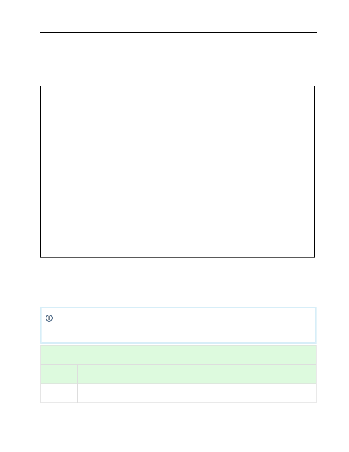
Channels 2, 3, and 4 are special purpose cameras. To ensure full functionality, assign
these channels appropriately, as defined in the legend in the following table.
CAMERA TRIGGER SIGNALS (DIGITAL INPUTS) LEGEND
Channel Camera Purpose
1,5, 6 General purpose cameras.
Making RVS-96D
Connections
Connections Overview
Camera Connection
Connect up to 6 cameras to the RVS-96D using camera connectors CH1 through
CH6.
COPYRIGHT © 2017 Rear View Safety
16
Page 17
RVS-96D Installation and Setup Guide
2
Reverse. Color back-up guides superimposed on view.
3
Left turn signal. Delayed cancellation of image display/record.
4
Right turn signal. Delayed cancellation of image display/record.
Power should NOT be connected to the vehicle's ignition key switch.
Camera Trigger Connections
Camera trigger wires must be connected to the vehicle's outputs.
Ensure that cameras with special associated trigger signals (i.e., Reverse, Left Turn, Right Turn)
are connected to the output terminals receiving the appropriate vehicle input signals to the terminal
block.
Power Connection
The 12V tap must be after the battery disconnect (i.e., turning battery disconnect off eliminates
12V to the mobile platform. Turning battery disconnect on reapplies 12V). Other names for the
battery disconnect are night switch and kill switch.
See RVS-96D Electrical Tapping Points Reference Guide.
Recommended RVS-96D Camera Locations
COPYRIGHT © 2017 Rear View Safety
17
Page 18

RVS-96D Installation and Setup Guide
Recommended RVS-96D Camera
Locations
and Settings
Optimal camera configuration will ultimately depend on customer preference and
the requirements involved for the various types of waste collection. As a guideline, Rear
View Safely proposes the following configurations based on actual installations performed by our
installation team. The configurations presented here are "minimal" configurations, i.e., not all 6
cameras need be used in each scenario. You can use as many cameras as you deem appropriate
for your particular application.
COPYRIGHT © 2017 Rear View Safety
18
Page 19

RVS-96D Installation and Setup Guide
Residential Front-Load (Curotto-Can)
Commercial Front-Load
COPYRIGHT © 2017 Rear View Safety
19
Page 20

RVS-96D Installation and Setup Guide
Roll-off and Rear-Load
Residential Side-Load
RVS-96D Electrical Tapping Points
COPYRIGHT © 2017 Rear View Safety
20
Page 21
RVS-96D Installation and Setup Guide
The material presented here is provided solely for the purposes of locating DC voltage
source locations within various vehicle types. The equipment depicted in the images is
not relevant within this context and, as such, may vary from that being used in your
installation.
RVS-96D Electrical Tapping
Points Reference Guide
COPYRIGHT © 2017 Rear View Safety
21
Page 22

RVS-96D Installation and Setup Guide
Quick Links - Sample Vehicle Installations
Mack - MRU
Mack - MR
Mack - LEU600
Mack - CT713
Autocar
Peterbilt
International - 7600
Freightliner - M2 12yd Minimax 2014
CCC
Sterling - Condor
American - LaFrance
Electrical Requirements
12v
The 12v tap must be after the battery disconnect (i.e., turning battery disconnect off eliminates 12v
to the Fleetmind mobile platform. Turning battery disconnect on reapplies 12v). Other names for
the battery disconnect are night switch and kill switch.
Ground
Most trucks have a dedicated ground stud while some trucks require locating the screw that is
tapped into the chassis as ground. Note that a clean ground implies direct contact to a rust free
metal surface.
Reverse & Brake
For both reverse and brake, the Fleetmind mobile platform is expecting a state change from 0v
(disengaged/off) to 12v (engaged/on).
COPYRIGHT © 2017 Rear View Safety
22
Page 23

RVS-96D Installation and Setup Guide
Mack - MRU
COPYRIGHT © 2017 Rear View Safety
23
Page 24

RVS-96D Installation and Setup Guide
Mack - MR
COPYRIGHT © 2017 Rear View Safety
24
Page 25

RVS-96D Installation and Setup Guide
MACK - LEU600
COPYRIGHT © 2017 Rear View Safety
25
Page 26

RVS-96D Installation and Setup Guide
Mack - CT713
COPYRIGHT © 2017 Rear View Safety
26
Page 27

RVS-96D Installation and Setup Guide
Autocar
12V & Ground (Configuration 1)
12V & Ground (Configuration 2)
COPYRIGHT © 2017 Rear View Safety
27
Page 28

RVS-96D Installation and Setup Guide
12V & Ground (Configuration 2)
COPYRIGHT © 2017 Rear View Safety
28
Page 29

RVS-96D Installation and Setup Guide
12V & Ground (Configuration 3)
COPYRIGHT © 2017 Rear View Safety
29
Page 30

RVS-96D Installation and Setup Guide
Brake and Reverse (Configuration 1)
COPYRIGHT © 2017 Rear View Safety
30
Page 31

RVS-96D Installation and Setup Guide
Brake and Reverse (Configuration 2)
COPYRIGHT © 2017 Rear View Safety
31
Page 32

Peterbilt
RVS-96D Installation and Setup Guide
COPYRIGHT © 2017 Rear View Safety
32
Page 33

RVS-96D Installation and Setup Guide
International - 7600
COPYRIGHT © 2017 Rear View Safety
33
Page 34

RVS-96D Installation and Setup Guide
Freightliner - M2 12yd Minimax 2014
COPYRIGHT © 2017 Rear View Safety
34
Page 35

CCC
RVS-96D Installation and Setup Guide
COPYRIGHT © 2017 Rear View Safety
35
Page 36

RVS-96D Installation and Setup Guide
Sterling - Condor
COPYRIGHT © 2017 Rear View Safety
36
Page 37

RVS-96D Installation and Setup Guide
American - LaFrance
COPYRIGHT © 2017 Rear View Safety
37
Page 38

RVS-96D Installation and Setup Guide
1.
2.
3.
1.
2.
Lift signal tap points
Peterbilt
The white wire on the camera harness is usually connected to a proximity switch on the arm
assembly.
White wire (1753 212) in a large bundled harness near the rear of the cab, leading to the
joystick.
2015 Scorpion trucks have a white wire underneath the joystick that has a programmable
output signal and can be triggered off any of the proximity switches on the arm.
Labrie Arms
The majority of Labrie systems have a wire labelled 235i inside the PTO box associated with
a proximity switch on the arm when it is elevated.
Other possiilities include wires labelled ‘Auto-cam switcher’ and ‘Arm Mid Position’.
Zero Radius – Autocar 2014
Behind an access panel located on the body, driver side, near the front, are a series of fuse
assemblies. A part of assembly 1483835, there is a green wire labelled ‘Arm up stowed prox’
associated with the proximity switch on the arm when stowed all the way up.
RVS-96D System Configuration
COPYRIGHT © 2017 Rear View Safety
38
Page 39

RVS-96D Installation and Setup Guide
1.
2.
Touch and hold the lower area of the screen to display the control panel.
Select .System
RVS-96D System Configuration
Accessing the System Configuration Menus
In order to set up system configuration parameters, you must use the system menus.
COPYRIGHT © 2017 Rear View Safety
39
Page 40

RVS-96D Installation and Setup Guide
3. Use the Admin user name and, If required, enter the password.
For first-time access, the default password "456789" is defined. You can change the
password later using the User Accounts menu.
The Main Menu displays.
COPYRIGHT © 2017 Rear View Safety
40
Page 41

RVS-96D Installation and Setup Guide
1.
2.
Setting Date/Time and Operating Language
Select .System Settings
The System Settings menu displays.
Select .General Settings
The General Settings menu enables you to set date and time parameters and choose an
operating language.
COPYRIGHT © 2017 Rear View Safety
41
Page 42

RVS-96D Installation and Setup Guide
a.
b.
c.
i.
ii.
iii.
d.
i.
ii.
You can set the date and time:
Manually
Automatically
To set date and time manually:
Touch their respective fields to display the numeric keypad.
Use the keypad to specify new values; use the arrow keys to move the cursor
position forward and backward.
Select when done.Enter
To set date and time automatically using UTC time (Coordinated Universal Time,
formerly Greenwich Mean Time, or GMT) reported by the GPS:
Select the check box.GPS time adopt
The time on the device is coordinated with UTC time.
To display local time for your current time zone, you must use the plus or
minus check boxes and the hours/minutes numeric menu to specify the
deviation from UTC.
COPYRIGHT © 2017 Rear View Safety
42
Page 43

RVS-96D Installation and Setup Guide
ii.
3.
4.
5.
1.
For Example
USA Eastern time is either UTC -5 or UTC -4, depending whether DST
is in effect.
Choose a date format.
Select a time format.
Select a language.
Setting Video Parameters
From the System Settings menu, select .Video Settings
COPYRIGHT © 2017 Rear View Safety
43
Page 44

RVS-96D Installation and Setup Guide
2.
3.
4.
The Video Settings menu enables you to specify video properties for each of the six
channels, which are selectable from the channel pull-down menu.
After you select a channel from the menu, you can apply properties for that channel as
described in the following steps.
Set the encode size, which determines the level of video compression.
Choose a type of bit stream, either fixed or dynamic, according to your requirements.
Dynamic can be used to adapt to changing network conditions in order to provide playback
with fewer stalls and/or re-buffering.
Select video encoding quality.
COPYRIGHT © 2017 Rear View Safety
44
Page 45

4.
5.
6.
7.
a.
b.
c.
d.
8.
9.
Select the frame rate—number of frames per second (fps).
Generally, the higher the FPS, the smoother the motion appears.
Set the bit stream rate.
time
(license) plate
channel
GPS
Use the check boxes to turn on or off the overlays.
To reposition the overlays:
RVS-96D Installation and Setup Guide
Set overlay positions.
RVS-96D provides 4 overlays for video that can be turned on or off and repositioned
on the screen:
COPYRIGHT © 2017 Rear View Safety
45
Page 46

9.
a.
b.
c.
10.
1.
2.
1.
Choose set position.
The screen refreshes, showing a preview image.
Touch a new position on the screen.
The overlay moves to the new position.
Press the button to return to the Video Settings screen.Back
Once you have finished specifying all settings, press to preserve your changes.Save
Copying Your Video Settings to Other Channels
To copy your settings from one channel to one or more of the other ones:
Press the button. Copy
A dialog displays prompting you for target channel(s).
Select your target channels, and then press .Ok
Specifying Record Settings
From the System Settings menu, select .Record Settings
RVS-96D Installation and Setup Guide
COPYRIGHT © 2017 Rear View Safety
46
Page 47

1.
2.
3.
The Record Settings menu enables you to set recording properties for each of the six
channels, which are selectable from the channel pull-down menu.
After you select a channel from the menu, you can apply properties for that channel as
described in the following steps.
With loop recording , the video files are stored on the memory card, with the newest video
continuously replacing the oldest video.
Select or from the loop recording pull-down menu.Yes No
Choose a loop length (in minutes) for each video segment.
RVS-96D Installation and Setup Guide
COPYRIGHT © 2017 Rear View Safety
47
Page 48

RVS-96D Installation and Setup Guide
3.
4.
5.
a.
b.
c.
6.
Choose a video format, NTSC or PAL.
NTSC is the most commonly used video system or standard used in North America and
most of South America, while PAL is common in Europe and parts of Asia.
Select the standard appropriate to your regional or technical requirements.
Stop Rec, Manual Rec, check boxes.Auto Rec
Stop Rec stops all recording.
Manual Rec sets manual mode recording. In this mode you can set up to 4 schedules
daily.
Auto Rec sets automatic mode recording. In this mode, recording is on at all times.
Select a recording plan.
For manual recording only. This option is not available for auto recording.
The recording plan defines a schedule for manual mode recording.
Use the menu below in conjunction with the hourly schedule menus to day-of-the-week
define up to 4 different schedules per day.
COPYRIGHT © 2017 Rear View Safety
48
Page 49

RVS-96D Installation and Setup Guide
7.
1.
2.
1.
Once you have finished specifying all settings, press to preserve your changes.Save
Copying Your Record Settings to Other Channels
To copy your settings from one channel to one or more of the other ones:
Press the button. Copy
A dialog displays prompting you for target channel(s).
Select your target channels, and then press .Ok
Specifying Alarm Settings
From the System Settings menu, select .Alarm Setting
The Alarm Settings menu enables you to set alarm properties for each of the six trigger
channels, which are selectable from the channel pull-down menu.
COPYRIGHT © 2017 Rear View Safety
49
Page 50

RVS-96D Installation and Setup Guide
2.
3.
4.
5.
6.
After you select a channel from the menu, you can apply properties for that channel as described in
the following steps.
Enable Status: use the check box to enable and disable alarms.
Dev type: choose or from the menu.high level low level
Alarm triggers can be either high voltage (high level) or GROUND (low level).
Alarm Delay (seconds).
Alarm delay is the length of time the alarm channel displays in full-screen mode and with a
recorder.
Rec Channel.
Use the check boxes to specify which channels to record when an alarm occurs on the
specified input channel.
Periods of time.
COPYRIGHT © 2017 Rear View Safety
50
Page 51

RVS-96D Installation and Setup Guide
6.
7.
1.
2.
1.
Alarm output.
Both options can be selected. I/O output can be used, for example, to send a signal to an
additional device such as a beeper.
Copying Your Alarm Settings to Other Channels
To copy your settings from one channel to one or more of the other ones:
Press the button. Copy
A dialog displays prompting you for target channel(s).
Select your target channels, and then press .Ok
Specifying Motion Detection Settings
From the System Settings menu, select Motion Detection.
COPYRIGHT © 2017 Rear View Safety
51
Page 52

RVS-96D Installation and Setup Guide
2.
3.
4.
The Motion Detection menu enables you to set motion detection properties for each of the
six channels, which are selectable from the channel pull-down menu.
After you select a channel from the menu, you can apply properties for that channel as
described in the following steps.
Enable Status: use the check box to enable and disable motion detection.
Select the alarm delay (in seconds) by pressing in the field and using the numeric keypad.
press when done.Enter
Alarm delay is the length of time the alarm channel displays in full-screen mode and with a
recorder.
Set detection region(s) for the channel:
COPYRIGHT © 2017 Rear View Safety
52
Page 53

4.
a.
b.
5.
6.
7.
8.
Press the button.Set
A grid displays on a green screen, where you can select detection regions by touching
squares on the grid.
.
After making your selection (one or multiple squares), press the button to return Back
to the Motion Detection screen.
Select a detection sensitivity level from the Sensitivity menu.
Use the check boxes to select channel(s) for recording when motion is detected.
Periods of time.
Alarm output.
RVS-96D Installation and Setup Guide
COPYRIGHT © 2017 Rear View Safety
53
Page 54

RVS-96D Installation and Setup Guide
8.
1.
a.
b.
1.
2.
As with alarms, both options can be selected. I/O output displays a yellow "motion" icon on
the screen..
Copying Your Motion Detection Settings to Other Channels
To copy your settings from one channel to one or more of the other ones:
Press the button. Copy
A dialog displays prompting you for target channel(s).
Select your target channels, and then press .Ok
Specifying Vehicle Information
Specifying vehicle and driver information is useful for data collection and analysis and for record
keeping.
Vehicle information is used for.....TBD
From the Main menu, select Vehicle Settings.
From the Vehicle settings menu, select Basic Info.
COPYRIGHT © 2017 Rear View Safety
54
Page 55

2.
3. Enter all information in the text fields.
This information is made available to the MDVR player software for viewing in the status
window during playback.
RVS-96D Installation and Setup Guide
COPYRIGHT © 2017 Rear View Safety
55
Page 56

RVS-96D Installation and Setup Guide
4.
1.
2.
Select when done.Save
Specifying G-Sensor Settings
From the Main menu, select Vehicle Settings.
From the Vehicle settings menu, select G-Sensor.
COPYRIGHT © 2017 Rear View Safety
56
Page 57

2.
3.
4.
The G-sensor menu enables you to specify accelerometer thresholds for the X, Y, and Z axes. These
are the thresholds at which the cameras will detect a sudden change in direction, which could be
caused by hard braking or impact from collision.
Make your choices from the menus, and then press .Save
To calibrate, TBD.
RVS-96D Installation and Setup Guide
COPYRIGHT © 2017 Rear View Safety
57
Page 58

RVS-96D Installation and Setup Guide
System Setup Menus
This section provides an overview of the RVS-96D System Menu hierarchy, along with images
of all menus and their options.
COPYRIGHT © 2017 Rear View Safety
58
Page 59

RVS-96D Installation and Setup Guide
Main Menu
System Settings
COPYRIGHT © 2017 Rear View Safety
59
Page 60

RVS-96D Installation and Setup Guide
General Settings
Video Settings
COPYRIGHT © 2017 Rear View Safety
60
Page 61

RVS-96D Installation and Setup Guide
Record Settings
Alarm Control
COPYRIGHT © 2017 Rear View Safety
61
Page 62

RVS-96D Installation and Setup Guide
Motion Detection
Monitor Display
COPYRIGHT © 2017 Rear View Safety
62
Page 63

RVS-96D Installation and Setup Guide
Advanced Options
COPYRIGHT © 2017 Rear View Safety
63
Page 64

RVS-96D Installation and Setup Guide
System Upgrade
Restore Default
COPYRIGHT © 2017 Rear View Safety
64
Page 65

RVS-96D Installation and Setup Guide
User Accounts
System Info
COPYRIGHT © 2017 Rear View Safety
65
Page 66

Memory Info
Version Info
RVS-96D Installation and Setup Guide
COPYRIGHT © 2017 Rear View Safety
66
Page 67

RVS-96D Installation and Setup Guide
File Backup
Format
COPYRIGHT © 2017 Rear View Safety
67
Page 68

RVS-96D Installation and Setup Guide
Vehicle Settings
COPYRIGHT © 2017 Rear View Safety
68
Page 69

Basic Info
G-Sensor
RVS-96D Installation and Setup Guide
COPYRIGHT © 2017 Rear View Safety
69
Page 70

RVS-96D Installation and Setup Guide
Playback
RVS-96D User Management
COPYRIGHT © 2017 Rear View Safety
70
Page 71

RVS-96D Installation and Setup Guide
1.
2.
Admin, a full-privilege administrator account. Privileges for this user account cannot be
modified.
Default, an account whose access privileges can be limited to certain functions.
In the current software version, it is not possible to add further user accounts.
From the Main menu, select .Advanced Options
From the Advanced Options menu, select .User Account
RVS-96D User Management
RVS-96D provides two built-in user accounts, neither of which can be
deleted:
You perform user management for RVS-96D using the User Accounts menu.
COPYRIGHT © 2017 Rear View Safety
71
Page 72

RVS-96D Installation and Setup Guide
3.
4.
The Username dialog displays.
Select a user name from the list.
To modify or create a password, select .Modify Password
Make your required changes, and then select .Ok
The RVS-96D is configured before shipping with the default password 456789.
COPYRIGHT © 2017 Rear View Safety
72
Page 73

RVS-96D Installation and Setup Guide
5.
6.
To modify access privileges (for Default account only), select .Modify Access
Make your required changes, and then select .Ok
COPYRIGHT © 2017 Rear View Safety
73
Page 74

RVS-96D Installation and Setup Guide
COPYRIGHT © 2017 Rear View Safety
74
Page 75

RVS-96D Installation and Setup Guide
System Information, Disk and File Management
System Info
COPYRIGHT © 2017 Rear View Safety
75
Page 76

RVS-96D Installation and Setup Guide
COPYRIGHT © 2017 Rear View Safety
76
Page 77

RVS-96D Installation and Setup Guide
Backup and Restore
Backup
Restore Default
COPYRIGHT © 2017 Rear View Safety
77
Page 78

RVS-96D Installation and Setup Guide
COPYRIGHT © 2017 Rear View Safety
78
Page 79

RVS-96D Installation and Setup Guide
1.
2.
Playing Back Videos
Touch lower area of screen to display controls.
Press the Playback button.
COPYRIGHT © 2017 Rear View Safety
79
Page 80

RVS-96D Installation and Setup Guide
3.
4.
Enter user name and password, if required.
Select a date/time range, and press .search
COPYRIGHT © 2017 Rear View Safety
80
Page 81

4.
5. Select a saved video from the list, and press .play
Video plays in the currently selected view (i.e.,two/four/six-panel view or full-screen).
RVS-96D Installation and Setup Guide
COPYRIGHT © 2017 Rear View Safety
81
Page 82

RVS-96D Installation and Setup Guide
Full-screen view
Control panel hidden
COPYRIGHT © 2017 Rear View Safety
82
Page 83

RVS-96D Installation and Setup Guide
To show the control, tap the lower area of the screen and select the menu option.
COPYRIGHT © 2017 Rear View Safety
83
Page 84

RVS-96D Installation and Setup Guide
Control Panel
COPYRIGHT © 2017 Rear View Safety
84
 Loading...