

Page 1
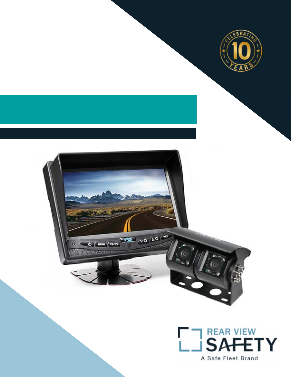
Instruction Manual
Backup Camera System With
Dual Lens Camera
RVS-813613-NM
Reverse With Condence ™
1
Page 2
Introduction.............................. 03
Safety Information.............................. 04-06
Before Beginning Installation . . . . . . . . . . . . . . . . . . . . . . 07
Installation Guide. . ........................... . 08-09
Adjustable Grid Line . ............................ 10
Installation and Wire.............................11-12
Camera Features . . . . . . . . . . . . . . . . . . . . . . . . . . . . . 13
Monitor Specications . . . . . . . . . . . . . . . . . . . . . . . . . . . 14
Camera Specications . . . . . . . . . . . . . . . . . . . . . . . . . . 15
TABLE OF CONTENTS
2
Warranty.......................... . . . . . 16
Disclaimer.......................... . . . . . 17
Rear View Safety
Page 3

NOTE!
Please read all of the installation instructions
carefully before installing the product. Improper
installation will void manufacturer’s warranty.
Congratulations on purchasing a Rear View Backup
Camera System!
With this manual you will be able to properly install and
operate the unit.
The Backup Camera System is intended to be installed as a
supplement aid to your standard rear view mirror that already exists
in your vehicle. The Backup Camera System should not be used as a
substitute for the standard rear view mirror or for any other mirror
that exists in your vehicle.
In some jurisdictions, it is unlawful for a person to drive a
motor vehicle equipped with a TV viewer or screen located forward of
the back of the driver’s seat or in any location that is visible, directly
or indirectly, to the driver while operating the vehicle.
INTRODUCTION
Reverse With Condence ™
3
Page 4

Please read the entire manual and follow the instructions and
warnings carefully. Failure to do so can cause serious damage and/or
injury, including loss of life. Be sure to obey all applicable local
trac and motor vehicle regulations as it pertains to this product.
Improper installation will void manufacturer’s warranty.
USAGE:
• The Rear View Camera System is
designed to help the driver safely detect people and/or objects
helping to avoid damage or injury.
However, you the driver, must use it
properly. Use of this system is not a
substitute for safe, proper or legal
driving.
• Never back up while looking at the
monitor alone. You should always
damage or injury. Always back up
slowly.
• The Rear View Camera System is
not intended for use during extensive back-up maneuvers or backing
into cross trac or pedestrian walkways.
•Please, always remember, the area
displayed by the Rear View Camera
check behind and around the vehi-
SAFETY INFORMATION
cle when backing up, in the same
way as you would if the vehicle did
not have the Rear View Camera
System. If you back up while looking
only at the monitor, you may cause
4
System is limited. It does not display
the entire panorama that is behind
you.
Rear View Safety
Page 5

INSTALLATION:
• Electric shock or product
malfunction may occur if this
product is installed
incorrectly.
• Use this product within
the voltage range specied. Failure
to do so can cause
electronic shock or product
malfunction.
or disconnected wire may cause a
re.
• While installing the Rear View
System be careful with the wire
positioning in order to avoid wire
damage.
• The Rear View System should only
be used when the vehicle is in
reverse.
SAFETY INFORMATION
• Take special care when
cleaning the monitor.
• Make sure to rmly ax the prod-
uct before use.
• If smoke or a burning smell
is detected, disconnect the
system immediately.
• Where the power cable may touch
• Do not watch movies or
operate the monitor while driving;
as it may cause an
accident.
• Do not install the monitor
where it may obstruct drivers
view or obstruct an air bag
device.
a metal case, cover the cable with
friction tape. A short circuit
Reverse With Condence ™
• Dropping the unit may cause
possible mechanical failure.
5
Page 6
If you have questions about this product, contact:
Rear View Safety
1797 Atlantic Avenue
Brooklyn, NY 11233
Tel: 1.800.764.1028
IN NO EVENT SHALL SELLER OR MANUFACTURER BE
SAFETY INFORMATION
LIABLE FOR ANY DIRECT OR CONSEQUENTIAL DAMAGES OF
ANY NATURE, OR LOSSES OR EXPENSES RESULTING FROM
ANY DEFECTIVE PRODUCT OR THE USE OF ANY PRODUCT.
6
Rear View Safety
Page 7

Before drilling please check that no cable or wiring is on the other side
of the wall. Please clamp all wires securely to reduce the possibility
of them being damaged while vehicle is in use. Keep all cables away
from hot/moving parts and electrical noisy components.
We recommend doing a benchmark test before installation
to insure that all components are working properly.
Step 1: Choose the monitor and camera locations.
Step 2: Install all cables in vehicle, when necessary a 0.8 (20mm)
hole should be drilled for passing camera cable through vehicles
walls. Install split grommets where applicable.
Step 3: Once all cables and wiring have been properly routed, perform
a system function test by temporarily connecting the system.
BEFORE YOU BEGIN
Reverse With Condence ™
7
Page 8

Cable
1. Be sure to position the cable properly. The camera cable uses aircraft
grade connectors which means the camera cable can be exposed to all
weather elements. Do not run the cable over sharp edges, do not kink
the cable and keep away from HOT and rotating parts.
2. Fasten all cables and secure all excess cable.
Monitor
1. To Attach the Pedestal mount to the dashboard or to the head-liner
use self-tapping screws and/or the adhesive pad.
2. Attach monitor to mount, and adjust mounting angle to allow optimum driver viewing comfort. (see gure 1.1 on page 12)
INSTALLATION GUIDE
8
Rear View Safety
Page 9

Wiring
To power the system connect the power (RED) 12V+ wire to ignition
power and the ground (BLACK) wire to chassis ground.
• These are the only wires needed to power the entire system and all
the cameras. Each camera can be seen at any time by simply pressing
the power button and using the V1/2 button to toggle.
• The three positive trigger wires (WHITE-CH1, BROWNCH2, BLUECH3) each represent one channel and will turn on their channel when
the trigger wire is energized with 12V.
• "Camera 3" is the designated backup channel. To have the the backup camera come on when you go into reverse, con-nect the BLUE wire
to reverse power (or any power source that comes on only in reverse).
• The other channels can similarly be triggered (i.e. side cam-eras can
be triggered by the turn signals etc.)
• To automatically have camera and monitor turn ON when vehi-cle
activates, simply twist BLUE positive trigger 12V+ to Red Power line
12V+ and wire to ig-nition power.
INSTALLATION GUIDE
Reverse With Condence ™
9
Page 10

• Audio: There is audio on channels 2 and 3. On channel 3 the blue
trigger wire must be energized (12V) to activate the audio. On
channel 2 the audio is always on.
• Grid-lines: The grid-lines are also carried through the blue wire.
To use the grid-lines for reversing, connect the blue wire to a reverse power.
• There is a built-in voltage regulator for our systems which can
handle 12-24 volts. Real consumption is 10 to 30 Volts.
INSTALLATION AND WIRE
1. Red - Power (+)
2. Yellow - Video
3. Green - Mirror / Normal Imaging
4. White - Audio
5. Black - Ground (-)
10
Rear View Safety
Page 11

Monitor
1
2
3
4
3 Amp Fuse
1. DC12V-24V (red)
INSTALLATION AND WIRE
2. Ground (black)
3. Port #3 (blue)
4. Port #2 (white)
5. Port #1 (yellow)
Reverse With Condence ™
11
Page 12

Camera selection
Menu
Power
Toggle selection
down
Toggle selection
up
Rotate Image
• "Brightness" "Contrast "Saturation" "Sharpness": adjust image properties
• Picture Adjust: Stretch image horizontally (right/left and left/right)
• Turn: Toggle between mirror/normal image on each individual channel
• Day/Night: Toggle between back-lit buttons and auto dimming
• Name: Change name of each individual channel
MONITOR OPERATION
• Trigger Source: Toggle channel destination for each trigger
• Trigger Delay: Adjust time delay on each trigger
• Distance Grid: Toggle which channel distance grid lines will display on
• Grid Position: Adjust grid lines
• Auto Power: On: Monitor will automatically turn on when powered.
O: Monitor will only turn on when triggered. Auto: Monitor will follow previous state.
• Reset: Reset settings to factory default
12
Rear View Safety
Page 13

Dual Camera - Perfect for Viewing Trac and Vehicle Bumper
130° Ultra-Wide all Encompassing View
18 Infra-Red Lights - 9 on Each Camera
Completely Waterproof - IP68 Rating
Built-in High Gain Mic
CAMERA FEATURES
Reverse With Condence ™
13
Page 14

Monitor Information
Type LED Digital Panel
Screen Size 7"
Dot Resolution 800 X 3 (RGB) X 480
Display Format/Contrast 16:09 / 500:01:00
Display Brightness 400cd/m
2
Video Input 3 channel CVBS
Video Source 1Vp-p, 750
Power Supply DC 9V - 32V
Power Consumption 5W
Audio Output 0.5W speaker
Operating Temperature -20°C ~ +70° C
Storage Temperature -30°C ~ +85°C
Video System Auto NTSC/PAL
Overall Dimensions 7" (L) x 5.25" (H) x 1" (D)
Weight 400G
Vibration Rating 5G
MONITOR SPECIFICATIONS
DOT PITCH 0.1926 (H) X 0.1710 (V)mm
Active Area 154.08(H) X 85.92(v)mm
Sync System Internal
14
Rear View Safety
Page 15

Camera Information
Camera
Picture Elements
Gamma Correction
Image Sensor
View Angle
Lens
Sync System
Infra-red distance
Usable Illumination
Power Source
S/N Ratio
1/3" Sony® CCD
250,000 pixels
r=0.45 to 1.0
480 TV Lines PAL: 500 (H) X 582
(V), NTSC: 510 (H) X 492 (V)
130°
2.1mm
Internal Synchronization
50 Feet (18 Infrared)
0 Lux (IR On)
DC 9v-32V
More than 48dB
CAMERA SPECIFICATIONS
Electronic Iris
Video Output
IR Switch Control
Vibration Rating
Video Output
Shutter Type
Vibration and Shock Rating
Operating Temperature
Storage Temperature
Dimensions
Storage Temperature
1/50, 160-1/100,000sec
1Vp-p 75
ACDS Automatic Control
5.8'
1Vp-p, 75
Electronic Rolling Shutter (ERS)
20G
-40°C ~ +50°C / RH 95% Max
-40°C ~ +60°C / RH 95% Max
3.25" (H) x 4" (L) x 2" (D)
-40°C ~ +70°C / RH 95% Max
Reverse With Condence ™
15
Page 16

ONE YEAR WARRANTY
REAR VIEW SAFETY, INC. WARRANTS THIS PRODUCT AGAINST MATERIAL DEFECTS FOR A
PERIOD OF ONE YEAR FROM DATE OF PURCHASE. WE RESERVE THE RIGHT TO REPAIR OR
REPLACE ANY SUCH DEFECTIVE UNIT AT OUR SOLE DISCRETION. REAR VIEW SAFETY, INC.
IS NOT RESPONSIBLE FOR A DEFECT IN THE SYSTEM AS A RESULT OF MISUSE, IMPROPER
INSTALLATION, DAMAGE OR MISHANDLING OF THE ELECTRONIC COMPONENTS. REAR VIEW
SAFETY, INC. IS NOT RESPONSIBLE FOR CONSEQUENTIAL DAMAGES OF ANY KIND.
THIS WARRANTY IS VOID IF: DEFECTS IN MATERIALS OR WORKMANSHIP OR DAMAGES
RESULT FROM REPAIRS OR ALTERATIONS WHICH HAVE BEEN MADE OR ATTEMPTED BY
OTHERS OR THE UNAUTHORIZED USE OF NONCONFORMING PARTS; THE DAMAGE IS DUE
TO NORMAL WEAR AND TEAR, THIS DAMAGE IS DUE TO ABUSE, IMPROPER MAINTENANCE,
NEGLECT OR ACCIDENT; OR THE DAMAGE IS DUE TO USE OF THE REAR VIEW SAFETY, INC.
SYSTEM AFTER PARTIAL FAILURE OR USE WITH IMPROPER ACCESSORIES.
WARRANTY PERFORMANCE
DURING THE ABOVE WARRANTY PERIOD, SHOULD YOUR REAR VIEW SAFETY PRODUCT
EXHIBIT A DEFECT IN MATERIAL OR WORKMANSHIP, SUCH DEFECT WILL BE REPAIRED WHEN
THE COMPLETE REAR VIEW SAFETY, INC. PRODUCT IS RETURNED, POSTAGE PREPAID AND
INSURED, TO REAR VIEW SAFETY, INC. OTHER THAN THE POSTAGE AND INSURANCE
REQUIREMENT, NO CHARGE WILL BE MADE FOR REPAIRS COVERED BY THIS WARRANTY.
WARRANTY DISCLAIMERS
NO WARRANTY, ORAL OR WRITTEN, EXPRESSED OR IMPLIED, OTHER THE ABOVE WARRANTY
IS MADE WITH REGARD TO THIS REAR VIEW SAFETY, INC. REAR VIEW SAFETY, INC. DISCLAIMS
WARRANTY
ANY IMPLIED WARRANTY OR MERCHANTABILITY OR FITNESS FOR A PARTICULAR USE OR
PURPOSE AND ALL OTHER WARRANTIES IN NO EVENT SHALL REAR VIEW SAFETY. INC.
LIABLE FOR ANY INCIDENTAL, SPECIAL, CONSEQUENTIAL, OR PUNITIVE DAMAGES OR FOR
ANY COSTS, ATTORNEY FEES, EXPENSES, LOSSES OR DELAYS ALLEGED TO BE AS A
CONSEQUENCE OF ANY DAMAGE TO, FAILURE OF, OR DEFECT IN ANY PRODUCT INCLUDING,
BUT NOT LIMITED TO, ANY CLAIMS FOR LOSS OF PROFITS.
16
Rear View Safety
Page 17

DISCLAIMER
REAR VIEW SAFETY AND/OR ITS AFFILIATES DOES NOT GUARANTEE OR PROMISE THAT THE
USER OF OUR SYSTEMS WILL NOT BE IN/PART OF AN ACCIDENT OR OTHERWISE NOT COLLIDE
WITH AN OBJECT AND/OR PERSON. OUR SYSTEMS ARE NOT A SUBSTITUTE FOR CAREFUL
AND CAUTIOUS DRIVING OR FOR THE CONSISTENT ADHERENCE TO ALL APPLICABLE TRAFFIC
LAWS AND MOTOR VEHICLE SAFETY REGULATIONS. THE REAR VIEW SAFETY PRODUCTS ARE
NOT A SUBSTITUTE FOR REARVIEW MIRRORS OR FOR ANY OTHER MOTOR VEHICLE
EQUIPMENT MANDATED BY LAW. OUR CAMERA SYSTEMS HAVE A LIMITED FIELD OF VISION
AND DO NOT PROVIDE A COMPREHENSIVE VIEW OF THE REAR OR SIDE AREA OF THE VEHICLE.
ALWAYS MAKE SURE TO LOOK AROUND YOUR VEHICLE AND USE YOUR MIRRORS TO CONFIRM
REARWARD CLEARANCE AND THAT YOUR VEHICLE CAN MANEUVER SAFELY. REAR VIEW
SAFETY AND/OR ITS AFFILIATES SHALL HAVE NO RESPONSIBILITY OR LIABILITY
FOR DAMAGE AND/OR INJURY RESULTING FROM ACCIDENTS OCCURRING WITH VEHICLES
HAVING SOME OF REAR VIEW SAFETY PRODUCTS INSTALLED AND REAR VIEW SAFETY AND/
OR ITS AFFILIATES, THE MANUFACTURER, DISTRIBUTOR AND SELLER SHALL NOT BE LIABLE
FOR ANY INJURY, LOSS OR DAMAGE, INCIDENTAL OR CONSEQUENTIAL, ARISING OUT OF THE
USE OR INTENDED USE OF THE PRODUCT. IN NO EVENT SHALL REAR VIEW SAFETY AND/OR
ITS AFFILIATES HAVE ANY LIABILITY FOR ANY LOSSES WHETHER DIRECT OR INDIRECT, IN
CONTRACT, TORT OR OTHERWISE INCURRED IN CONNECTION WITH THE SYSTEMS,
INCLUDING BUT NOT LIMITED TO DAMAGED PROPERTY, PERSONAL INJURY AND/OR LOSS OF
LIFE. NEITHER SHALL REAR VIEW SAFETY AND/OR ITS AFFILIATES HAVE ANY
RESPONSIBILITY FOR ANY DECISION, ACTION OR INACTION TAKEN BY ANY PERSON IN
RELIANCE ON REAR VIEW SAFETY SYSTEMS, OR FOR ANY DELAYS, INACCURACIES AND/OR
ERRORS IN CONNECTION WITH OUR SYSTEMS FUNCTIONS.
DISCLAIMER
Reverse With Condence ™
17
Page 18

If you have any questions
about this product, contact:
Rear View Safety, Inc.
1797 Atlantic Avenue
Brooklyn, NY 11233
800.764.1028
Better Cameras. Better Service.
IT’S OUR GUARANTEE.
18
Rear View Safety
 Loading...