

Page 1

BIRD'S EYE VIEW CAMERA SYSTEM
Installation and
User Guide
RVS-77550
Page 2

BIRD'S EYE VIEW CAMERA SYSTEM
Contents
Introduction ..........................................................................................................................................4 1.
Installation Principles ...........................................................................................................................4 2.
2.1.
Installer Qualifications ..........................................................................................................4
2.2. Positive Switch Signals Required ........................................................................................4
2.3. Reverse Wiring.....................................................................................................................4
2.4. Turn Signal Wiring................................................................................................................4
System Package..................................................................................................................................8 3.
3.1.
Component List ....................................................................................................................8
3.2. Optional Shrouds for Specific Mounting Requirements .......................................................8
Installation Diagram ............................................................................................................................11 4.
Electronic Control Unit (ECU) ........................................................................................................... .12 5.
5.1.
ECU Installation Locations ................................................................................................ 10
5.1.1. ECU Installation Requirements ............................................................................ 11
5.1.2. Installing the ECU ................................................................................................ 12
Installing the Push-button Remote Control (optional) ...................................................................... 15 7.
Installing Cameras ............................................................................................................................ 16
8.1.
Determining Camera Locations ........................................................................................ 16
8.2. Installing Side Cameras Below Mirrors ............................................................................. 17
8.2.1. Selecting Symmetrical Side Camera Locations ................................................... 18
8.2.2. Under Mirror and Door Mount Option .................................................................. 19
8.2.3. Removing Mirror Glass ........................................................................................ 20
8.2.4. Mounting Cameras on Doors ............................................................................... 21
8.3. Camera Installation Procedure ......................................................................................... 23
8.3.1. Camera Assembly ................................................................................................ 24
Connecting to Signals and Power .................................................................................................... 25 9.
Testing and Calibration .................................................................................................................... 25
Connecting to a DVR (optional)........................................................................................................ 26
Installing in Fleet Vehicles ................................................................................................................ 27
12.1.
Conventional School Buses .............................................................................................. 28
12.2. Conventional Transit Buses .............................................................................................. 29
12.3. Para Transit or Short School Buses ................................................................................. 30
12.4. Fire Trucks ........................................................................................................................ 31
Using the System ............................................................................................................................. 32 13.
Specifications ................................................................................................................................... 34
8.
10.
11.
12.
14.
Warranty ........................................................................................................................................... 35
Contact Rear View Safety................................................................................................................. 36 16.
BIRD'S EYE VIEW CAMERA SYSTEM
15.
Page 3

1. Introduction
This guide describes how to install and use the Bird's Eye View Camera System. The
RVS-77550 provides drivers with a real-time, 360-degree picture of the area around their
vehicle to eliminate blind spots, help improve pedestrian safety, prevent vehicle damage,
and avoid liability costs.
For a description of how the system works, please see section 13 “Using the System” on
page 32.
2. Installation Principles
2.1. Installer Qualifications
Installation of the Bird's Eye View Camera System is for certified personnel only. For more
information, contact Seon Service and Support (please see the back page of this guide for
details).
BIRD'S EYE VIEW CAMERA SYSTEM
The installation process involves drilling into the exterior of a vehicle to mount cameras.
Ensure you read this document carefully, and verify the correct mounting locations prior to
drilling.
Important: The installed system will not operate correctly until it has been calibrated. For
more information, see the Bird's Eye View Camera System Calibration
Guide included with the product Installation and Calibration kit.
Check that you received all system components (for more information, see section 3.1 on
page 6), and inspect the units for any scratches or damage before installing.
2.2. Positive Switch Signals Required
The three signal attachments must be positive switching inputs, the Electronic Control Unit
(ECU) cannot accept a negative switching signal. The signals must be clean and not multipurpose. In many new commercial fleet vehicles the body control module (BCM) decides
when vehicle lighting turns on and off. While this has some efficiency in the scheme of
things, it does alter how we test for the correct wire.
Page 4 of 36
Page 4
BIRD'S EYE VIEW CAMERA SYSTEM
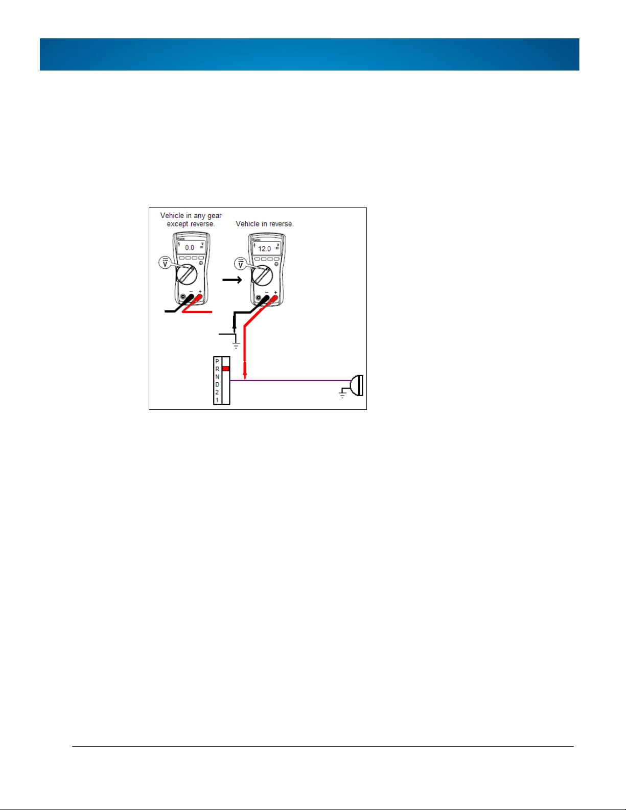
2.3. Reverse Wiring
The reverse signal is typically straightforward: connect to the wire that shows 12v when the
reverse lever is activated and reverse lights come on.
We highly recommend that a vehicle operator assists whenever testing the reverse signal to
ensure control of the vehicle.
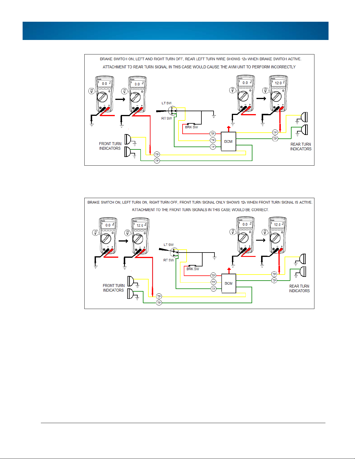
2.4. Turn Signal Wiring
The left and right turn signal wiring can be somewhat different in newer commercial
vehicles. There is no longer a requirement to have the rear turn signals a different color
(amber) than the brake lights (red) - they may all simply be red. This fact, combined with the
addition of a Body Control Module, allows the vehicle manufacturer to use the left and right
turn wires to display a brake signal, simply by activating them both at the same time. This
also allows the use of a single bulb and a single wire to do both. The ECU can detect and
ignore when both left turn and right turn signals are active at the same time, but it cannot
detect either turn signal independently.
Therefore, when applying the brake and activating a turn signal while navigating a turn, the
turn would go undetected, as the brake has already applied 12v to both left turn and right
turn:
Page 5 of 36
Page 5
BIRD'S EYE VIEW CAMERA SYSTEM
The correc
lights, as there is no brake output to those lights:
t attachment point to a vehicle wired in this manner is to the front turn signal
Page 7 of 36
Page 6

3. System Package
The typical contents are shown below (actual contents for your system may vary, depending
on the options selected):
BIRD'S EYE VIEW CAMERA SYSTEM
3.1. Component List
This identifies the components in the image that follows:
1. Electronic Control Unit (ECU), 4 screws
(SD Card for calibration not included)
2.
3. Power connection cables, fuses and fuse holders (1A, 3A)
4. Monitor video-in cable to connect to ECU
5. Reverse signal wire
6. Left and right signal wires
7. INTERFACE harness
8. VIDEO harness
9. POWER harness
10. Remote controller button and extension cable (optional)
11. Video output cables to monitor and DVR (optional)
Page 8 of 36
Page 7

BIRD'S EYE VIEW CAMERA SYSTEM
12. Camera extension cables (x4)
13. Camera, mounting plates, covers, drill template and screws (x4)
14. Screw covers (2 per camera)
Page 9 of 36
Page 8

BIRD'S EYE VIEW CAMERA SYSTEM
3.2. Optional Shrouds for Specific Mounting Requirements
While the inView 360 Around Vehicle Monitoring system ships with a standard commercial
kit as shown above, the following shrouds may be used in particular installations.
These mounting shrouds are special order only and do not come as part of the standard
package.
The optional shrouds are plastic, while the shrouds included in the standard commercial kit
are all metal.
Page 10 of 36
Page 9

4. Installation Diagram
BIRD'S EYE VIEW CAMERA SYSTEM
Page 11 of 36
Page 10

5. Electronic Control Unit (ECU)
5.1. ECU Installation Locations
When deciding on a mounting location for the ECU, ensure you take into account that the
calibration process will require access to each side of the unit:
• to insert and remove the SD card
• to plug and unplug the power connector
Install it in a covered, dry, but accessible location. Also consider cable lengths when laying
out the location of the unit.
Keep in mind the length of the monitor cable, as it isn’t shipped with a video cable extension,
and the supplied video cable will need to reach the ECU from the monitor position.
Here are a few ideal locations:
BIRD'S EYE VIEW CAMERA SYSTEM
Page 12 of 36
Page 11

5.1.1. ECU Installation Requirements
Ventilation
Install the ECU away from any sort of heat outlet, heater, or AC
Secure surfaces
Do not mount the ECU to a plastic panel or other surface that
Mounting
The ECU can be installed horizontally, vertically, or upside down.
Clearance around
Allow sufficient clearance: at least six (6) inches in front of the ECU
Power, Signal,
Provide enough slack on the power cable to prevent any force
blower.
Do not operate the ECU in a closed-in area or restrict ventilation in
any way.
The ECU requires air circulation to maintain optimum operating
temperature and provide best performance.
Do not expose the ECU to moisture.
cannot support the ECU’s weight or is subject to constant
vibration.
BIRD'S EYE VIEW CAMERA SYSTEM
orientation
the ECU and
(optional) DVR
Camera cables
and two (2) inches on each side for removal of the security front
cover and easy access to the hard drive and USB ports.
Allow sufficient clearance behind the DVR for power, signal, and
camera cables.
from being exerted on the connectors.
A single 4-inch diameter loop is sufficient.
Avoid right angle bends in the Ethernet cables.
Page 13 of 36
Page 12

BIRD'S EYE VIEW CAMERA SYSTEM
5.1.2. Installing the ECU
Install with SD card (UPDATE) slot accessible, and leave room to connect cables in the back.
1. Choose a location as described above, and use the unit to mark drill positions.
2. Drill screw holes.
3. Mount the ECU with 4 screws, supplied with an optional install plate for easier
removal if needed.
Page 14 of 36
Page 13
BIRD'S EYE VIEW CAMERA SYSTEM
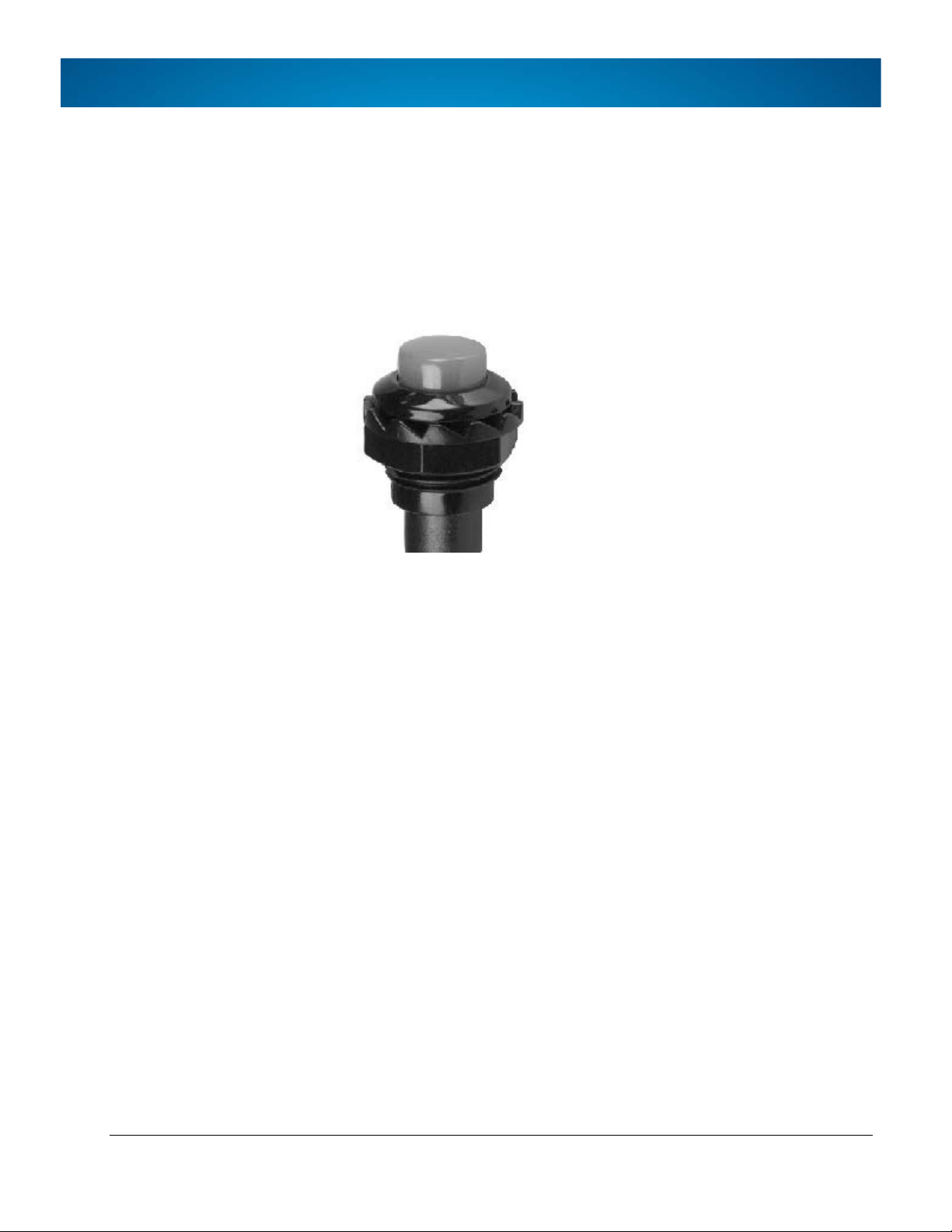
7. Installing the Push-button Remote Control (optional)
The remote controller has a blue button and a 1x2 connector for the extension cable, which
then connects to the BUTTON (1x4 male) connector on the INTERFACE harness.
1. Choose
2. Drill a 7/16” hole.
3. Thread the switch through the hole.
4. Tighten the nut to the underside of the switch.
5. Connect to the extension cable.
6. Run the extension cable to the ECU.
7. Connect the cable to the 1x4 BUTTON connector on the ECU INTERFACE harness.
a location on the switch panel.
Page 15 of 36
Page 14

8. Installing Cameras
8.1. Determining Camera Locations
Important: Confirm that camera positions will capture the required video before drilling
1. Attach the cameras temporarily with tape or velcro.
2. Connect them to the ECU and power on the system.
3. Calibrate the camera views in the Seon Calibration software (for details, see the
4. When positions are confirmed, install the cameras.
BIRD'S EYE VIEW CAMERA SYSTEM
holes in the vehicle.
inView 360 Calibration Guide included with the product Installation and
Calibration kit).
The cameras see a 150 degree range of video. They need to be mounted as high up and as
close to the centers of the vehicle sides as possible for maximum view overlap during the
calibration stage.
Page 16 of 36
Page 15

BIRD'S EYE VIEW CAMERA SYSTEM
8.2. Installing Side Cameras Below Mirrors
All four cameras in the Seon package are the same, and require 150 degrees of unimpeded
view from a parallel perspective of the vehicle. The view must not include side mirrors.
This is critical in placing the cameras, as shadowing can occur if the camera image that would
typically capture the ground is catching the protruding side mirrors, as in the case shown
below. The effect tends to produce parallel lines (shadow lines) in the calibrated software,
and it gives an undesirable appearance.
The first step in understanding camera placement for a 360-degree view system is to
recognize the range of the cameras being installed: the effective angle range of the inView
360 cameras is 150 degrees parallel to the side of the vehicle.
Imagine inverting a protractor and placing it on top of the vehicle image. This will give a close
estimate to help you choose where to look for an acceptable place to mount the camera.
As a rough template, we recommend you make a simple template similar to the pink version
pictured above, cut it out and simply lay it on an image of the vehicle. If you do not have an
image, you can take a picture on your smart phone.
This isn’t meant to be an exact measurement of where to place the camera to avoid mirrors it is to give you an idea of the areas that should work.
Page 17 of 36
Page 16

BIRD'S EYE VIEW CAMERA SYSTEM
When working on a new vehicle for the first time, the cameras should be temporarily
attached to the vehicle, and the side images examined to determine if the camera image can
see the side mirrors. The rule of thumb is typically that the shorter a vehicle is, the lower the
cameras may need to be to avoid the mirrors in the image.
Once po
both sides of the vehicle and find areas that are an option.
tential areas for side camera placement are established, the next step is to look at
8.2.1. Selecting Symmetrical Side Camera Locations
Side ca
While the driver’s side of the van pictured above appears to have a lot of options, the
passenger side has far fewer. The passenger side has a sliding door, and all electrical
connections are made into this door by contacts when the door is closed.
mera locations must be symmetrical to calibrate the system.
The section beyond this door toward back is also unacceptable as a mounting location, as
the door slides over this area, and would likely hit a camera mounted there. Therefore, the
only symmetrical position available would be somewhere on or within the forward green
section, or underneath the mirrors.
Page 18 of 36
Page 17

BIRD'S EYE VIEW CAMERA SYSTEM
All four cam
body as possible while minimizing image capture of the vehicle itself or protruding
equipment, to avoid shadowing.
eras must be mounted at the furthest point toward the outside of the vehicle
8.2.2. Under Mirror and Door Mount Option
While the under-mirror mount does appear to solve some shadowing issues created by body
panel mounting, it is not for a novice installer.
It requires disassembling the door panel, removing and disassembling mirror housings,
running wiring through the door into the vehicle, and in some cases dealing with moles in
the doors.
Do not attempt the above, unless you are experienced at this level.
This application is not possible in all types of power or standard mirrors: the mirror itself
should meet the criteria below before it is determined that placement is viable:
Page 19 of 36
Page 18

BIRD'S EYE VIEW CAMERA SYSTEM
• The mirror must have adequate extra space inside the mirror housing.
• The mirror must be flat on the bottom, and have enough surface area to
allow for mounting the cover. A 1 1/8” (28mm) diameter hole is required to
accommodate the camera.
• The mirror housing must have a pathway to run the camera cable wiring.
• Some door wiring is connected at the jam with a large Molex; the customer
must be OK with an alternate (possibly less attractive) routing for this cable.
The first step in installing cameras in mirrors is to remove the glass from the mirrors.
This can be a daunting task, and rarely are two models alike. It is glass that is being
unclipped, and it can be broken care is not taken.
The mirror glass will be attached most often with 4-6 tiny clips, similar to what is
pictured above. These clips are plastic and can be broken easily. It is recommended
that attempting to pry the glass off not be done in a cold environment, as the plastic
is far more brittle at lower temperatures.
8.2.3. Removing Mirror Glass
1. Get under the mirror and tilt the glass all the way in at the top, exposing as much
area as possible; if you can, identify a small rectangular area between the glass
and the round plastic turret that the clips are hanging on to.
2. Using a large flat head screwdriver, slide the tip in the rectangular area and
attempt to gently pry the mirror free. Be sure to hold the mirror as you are doing
this.
Page 20 of 36
Page 19

BIRD'S EYE VIEW CAMERA SYSTEM
If the
mirror does not pop free easily, do not force it.
3. Examine the mechanism further and consider if a different pry location might be
better.
4. Once the glass has been detached, proceed to removing the interior door panel
and the outside mirror housing.
5. If there is adequate room to drill the hole and mount the camera into the bottom
of the housing without impeding the motor, tilt mechanism, or manual cable,
then proceed with mounting the camera into the mirror.
The camera itself must be parallel to the side of the vehicle.
A common mistake is thinking screw holes in the under-mirror mount are 90
degrees perpendicular to the side of the vehicle – they are not.
8.2.4. Mounting Cameras on Doors
If you determine that under-mirror mounts are not an option and the side cameras must go
on the front door area, the standard industrial shrouds can be used to do this.
A thorough examination of the inside of the door, the window, window travel, and door
mechanism must be made when choosing a location for the side cameras.
An incorrect location can very easily lead to windows being ruined and/or scratched,
mechanisms being impeded, and wires being frayed or just snapped off all together. We
recommend plugging window switches back in and testing the up and down motion with the
door panel off prior to drilling any holes.
Regardless of whether the camera is mounted under the mirrors or in the door body, the
wiring must feed into the vehicle.
Page 21 of 36
Page 20

BIRD'S EYE VIEW CAMERA SYSTEM
Typically this is done through the existing rubber door boot. While it is typically not easy to
get extra wiring through this boot, it can usually be done. A more significant challenge often
comes at the door side of the boot. Many domestic manufacturers have opted to install a
Molex plug at this end.
Determine if there is enough empty space available in the plug to drill and slide the camera
wiring through. If not, you must find an alternate location to run the wiring into the vehicle.
This could mean drilling a new hole in the door jam to accommodate the wire entry.
It is imperative to find a location to minimize the frequent motion stress this wire will be
under. It is also very important that any wiring entering the vehicle body drop below the
entry point of the vehicle. If the wire strings into the vehicle downward without a ‘drip loop’,
water will follow the wire into the vehicle.
Upon reassembly of the Molex back into the vehicle, ensure all electrical door items are
operational.
Page 22 of 36
Page 21

8.3. Camera Installation Procedure
Camera position
Test position before mounting - be sure the location will
Mount to secure surfaces only - do not mount the
Mounting orientation
Ensure cameras are horizontally level.
Mirrors
Mount at a height where camera views will not be
Follow these guidelines:
work (for important details, see the previous section).
BIRD'S EYE VIEW CAMERA SYSTEM
Mounting surface
1. On th
2. At the mid-point of the vehicle widths and lengths, select a location.
3. Use Velcro or tape to adhere the camera to the vehicle for testing before drilling
4. Once positions have been verified, use the supplied camera drill templates to
e floor with a clear area around the vehicle of at least 6 feet in each
direction, use tape to make a rectangle enclosing the vehicle that includes the
maximum length and width.
holes (for more information, see the Calibration Guide included with the
Installation and Calibration Kit).
mark drill positions.
camera to movable or flexible surfaces.
obstructed by mirrors.
5. Drill the holes and remove the drill template from the vehicle surface.
Page 23 of 36
Page 22

BIRD'S EYE VIEW CAMERA SYSTEM
8.3.1. Camera Assembly
The cameras are sealed, and must be attached to the cover and mounting plate. Take care
not to lose any critical hardware - replacement screws may be very hard to source if they are
lost.
1. Collec
2. Attach the camera to the base plate with the 2 small screws.
3. Thread the camera cable through the hole and fit the grommet on the cable
4. Remove the adhesive on the back plate.
5. Place the base on the vehicle surface. Align to the drilled holes.
6. Remove the adhesive on the camera lens.
7. Place the camera cover over the camera.
8. Fasten the cover to the vehicle with the two black screws.
9. Cover the screws with the black round adhesive screw covers.
10. Seal the camera base with waterproof caulk.
11. Inside the vehicle, connect the camera cable to the extension cable.
t the camera, mounting plate and 2 small screws, cover plate and 2 black
screws, and screw covers.
hole’s edges.
12. Run the extension cable to the ECU and connect them.
13. Repeat for each camera.
Page 24 of 36
Page 23

9. Connecting to Signals and Power
The inView 360 Around Vehicle Monitoring system requires six electrical connections to the
vehicle:
• Power for ECU and Monitor
• Ignition (switched or accessory) for ECU and Monitor
• Vehicle ground
• Left turn signal
• Right turn signal
• Reverse for ECU and Monitor
All required system inputs are 12v (or 24v) positive inputs.
1. Run wires from the ECU POWER harness to left turn, right turn, and reverse
signals. All signals must be positive.
2. Run wires from the ECU POWER harness to ignition, power, and ground.
BIRD'S EYE VIEW CAMERA SYSTEM
3. Install 3A fuse on the power connection.
4. Install 1A fuse on the ignition connection.
10. Testing and Calibration
Power on the system and check the basic functionality (for details, see section 13,
“Using the System” on page 32:
Note: The 360 view itself will not display correctly until you calibrate the system
(see step 3, below).
1. Test that the monitor comes on and switches views when the turn signals and
reverse gear are engaged.
2. If your system includes the optional remote control, test that the button switches
views.
3. Calibrate the system according to the procedures described in the inView 360
Calibration Guide (included with the Installation and Calibration Kit).
Page 25 of 36
Page 24

11. Connecting to a DVR (optional)
While the system has a monitor to assist with driving and parking, Seon also offers the ability
to install a DVR and record the viewed image, in the same way that the DVR records a single
camera. An adapter (ARMF MicroFit to composite RCA) is all that is required to do this.
Recording the 360 camera view has some significant advantages: in the case of an accident,
it could provide critical video, and help establish what led to the crash. Center and lanedividing lines are typically visible on the monitor and in the recorded image.
Some DVRs such as the Seon TL-HD have a power output that can be utilized, allowing the
system to continue to record the 360-degree image after the vehicle ignition has been
turned off.
Follow these steps:
1. Connect the ARMF cable`s 2x3 MicroFit to an unused DVR camera socket.
BIRD'S EYE VIEW CAMERA SYSTEM
2. Connect one of the ARMF cable’s RCA connectors to a CVBS cable’s RCA
connector.
3. Connect the CVBS cable to a 2x1 connector on the VIDEO harness, connected to
the ECU.
4. Power on and test that the 360 video is displaying as a DVR camera input.
Page 26 of 36
Page 25

12. Installing in Fleet Vehicles
In this guide, “fleet vehicles” refers to vehicles of approximately 20-foot length such as
standard size work vans, mini work vans, bucket trucks, etcetera.
The majority of fleet vehicles require the standard Seon commercial kit. There may be some
exceptions to the mount for the front (forward-facing) camera, but the side and rear
cameras should be appropriate.
The side camera images must not capture the side mirrors. There are 150 degrees of
effective parallel view to the side of the vehicle where the side mirrors should not be in the
in the image. This should be tested by taping the camera to the side of the vehicle and
capturing the image.
If the calibration pads are in view with the side camera, and the side mirrors are not, the
image is typically acceptable. It is the goal to have the side cameras as high as possible, while
missing the side mirrors entirely.
BIRD'S EYE VIEW CAMERA SYSTEM
Recommended Shrouds:
• Front - Standard Optional (front or top)
• Rear - Standard
• Sides - Standard
For more information, see section 3.2, “Optional Shrouds for Specific Mounting
Requirements” on page 8.
Page 27 of 36
Page 26

BIRD'S EYE VIEW CAMERA SYSTEM
12.1. Conventional School Buses
Installation in most full-size school buses is fairly straightforward. Due to vehicle length, the
side and rear cameras may be installed around the top perimeter. These are typically
standard wire runs when installing surveillance cameras inside the bus.
The front camera may also be installed on top in the transit-style (flat nose) school bus, but
the mirror locations should be assessed prior to determining this.
In the conventional school bus example below, the front camera is installed in the front grill,
to avoid the hood. Regardless, all wire runs in this type of vehicle should be straightforward.
Recommended Shrouds:
• Front - Standard
• Rear - Standard
• Sides - Standard
Page 28 of 36
Page 27

BIRD'S EYE VIEW CAMERA SYSTEM
12.2. Conventional Transit Buses
Installing the system in a standard 40-foot transit bus is very similar to the process for a 40foot school bus. The wire runs for this vehicle are fairly standard. We advise testing the front
view prior to mounting the camera up high.
In most cases, public transit vehicles will have fold down bike racks on the front of the
vehicle, limiting the option to install below the windshield.
Typically, the ECU can be installed in the overhead compartment above the operator or radio
cabinet.
The system is not compatible with the negative-switching turn signals found in many full size
transit vehicles: the positive-switching signals must be located. Most modern full size transit
vehicles have multiplex circuitry – this likely requires running a reverse trigger wire to the
back of the vehicle and tapping the output from the node there. There will generally not be
anything useful in the front section.
mmended Shrouds:
Reco
• Front - Standard
• Rear - Standard
• Sides – Standard
Page 29 of 36
Page 28

BIRD'S EYE VIEW CAMERA SYSTEM
12.3. Para Transit or Short School Buses
Installing the system in a cutaway transit vehicle may be more involved than a full size transit
vehicle. Due to the domestic chassis portion of the vehicle being narrower than the rear
body, the cameras must be mounted on the rear body. Due to the length of the vehicle and
the mirrors protruding from the sides, the cameras will most likely require being installed
below the side windows.
Because of the materials used and the way the bus is constructed, to properly mount the
cameras, a hole must usually be drilled from the outside into the vehicle. It is very unlikely
there is a way to wire between these panels after the bus is assembled. Therefore, a flat
conduit is required to shroud the wiring after it enters the cab of the vehicle. This is far from
ideal, and should be discussed with the customer before proceeding. The camera location is
necessary for successful calibration (for more information, see the inView 360 Calibration
Guide, included with the Installation and Calibration kit).
Recommended Shrouds:
• Front - Standard Optional (front or top)
• Rear - Standard
• Sides – Standard
For mo
Requirements” on page 8.
re information, see section 3.2, “Optional Shrouds for Specific Mounting
Page 30 of 36
Page 29

BIRD'S EYE VIEW CAMERA SYSTEM
12.4. Fire Trucks
Note: This product is designed for a standard-length fire truck, and is not compatible with
a tractor-trailer version due to the pivot of the forward-facing camera.
Installing the system in a fire truck requires temporary placement of the side cameras prior
to drilling and mounting. Due to the construction of most fire trucks, side cameras will likely
not be mounted in the center of the vehicle, and instead will be more toward the front. We
highly recommend mounting the cameras high enough to see past the rear of the fire truck,
but low enough so as not to see the side mirrors in the image.
Most fire trucks have no access back through the rear portion of the body to wire anything regardless of fire truck type (utility, pumper, or ladder truck). The rear camera and reverse
wiring must be picked up at the rear of the fire truck, and run with the factory wiring
underneath the vehicle, then up into the cab-over section.
All wiring should be covered with convoluted tubing. This is a heavy industrial vehicle,
sometimes used in very harsh conditions. The system must be installed at a facility where a
lift is available, as well as the properly trained people to operate it.
Recom
mended Shrouds:
• Front - Standard
• Rear - Standard
• Sides - Standard
Page 31 of 36
Page 30

13. Using the System
Start the vehicle:
Shift into reverse gear:
Activate left turn signal:
Activate right turn signal:
360-degree stitched
Forward camera view
Rear camera view
Left-side camera view
Right-side camera view
When you turn on the ignition, the monitor displays a split-screen: the left side is a blended
(stitched) 360-degree “bird’s eye” view of all 4 camera images, and the right side shows the
forward camera. The image on the right changes, based on vehicle operation:
BIRD'S EYE VIEW CAMERA SYSTEM
view (4 cameras)
(with guide lines)
In the 36
0 view, the picture of the vehicle itself (seen from above) is a static image, selected
during system configuration. For more information, see the inView 360 Calibration Guide
included with the product Installation and Calibration kit.
Page 32 of 36
Page 31

Activating a turn signal or shifting the vehicle into reverse gear over-rides the current view.
Front full view:
Rear full view:
Cancelling the turn signal or shifting out of reverse returns to the default (360/forwardfacing) view.
Remote Control (Optional)
Use the optional switch (blue push-button) to cycle through the four split-screen displays
shown on the previous page, as well as full-screen images for the front and rear cameras:
BIRD'S EYE VIEW CAMERA SYSTEM
Page 33 of 36
Page 32

14. Specifications
Input Voltage
12V ~ 24V (Free Voltage)
Power Consumption
13W (ECU + 4 cameras), 0.6W per camera
Video Input
NTSC, Front/Rear/Left/Right Camera (4CH)
Video Output
NTSC, CVBS (SD) 2CH
Operating Temperature
-30°C ~ +75°C
Storage Temperature
-40°C ~ +75°C
Camera View
150° (Horizontal)
Resolution
800 x 480 (Optimized for monitor)
Frame Rate
30 FPS
Camera Cable Length
20”
Extension Cable Lengths
Front: 26’
Cut Off Requirement
< 8V accessory voltage
Weight
Entire kit: ECU, cameras, monitor, cables = 8 lbs.
Dimensions
ECU: 4.54” x 6.24” x 1.34”
Specifications for the inView 360 Around Vehicle Monitoring system are subject to change
without notice.
BIRD'S EYE VIEW CAMERA SYSTEM
Side: 39.5’
Rear: 52’
Cameras: 2.3” L x 2” H x 2” W
Page 34 of 36
Page 33

15. Warranty
BIRD'S EYE VIEW CAMERA SYSTEM
BIRD'S EYE VIEW CAMERA SYSTEM cameras are covered by a 1-year warranty (from the
date of purchase) on parts and repair labor.
Page 35 of 36
Page 34

BIRD'S EYE VIEW CAMERA SYSTEM
16. Contact Rear View Safety
Rear View Safety , INC. | 1797 Atlantic Avenue | Brooklyn NY 11233
800.764.1028 | Sales@RearViewSafety.com | www.RearViewSafety.com
Page 36 of 36
 Loading...