

Page 1
Mobilemule™
MobileMule™
5 Channel Mobile DVR with GPS (HDD)
Instruction Manual
We strongly advise our clients to monitor our website for notifications and implementing changes as made
necessary regarding the above.
We also strongly encourage constructive User feedback regarding errors.
Page 2

- 2 -
Mobilemule™
USING THE USER INTERFACE (UI)
The DVR User Interface is designed to be clear, concise, consistent and easy to use for system setup, use
and change. All selections and data entries are thru the use of the IR Remote Control (IRC) and the Virtual
Keyboard. Read the dedicated pages regarding their use and the operational cues within the Screen Features.
User Index
USING THE USER INTERFACE (UI) .................................................................. - 2 -
IR REMOTE CONTROL (IRC) FUNCTION KEYS ................................................... - 4 -
IR REMOTE CONTROL USE FOR DATA ENTRY (IRC) .......................................... - 5 -
TYPICAL UI PAGE LAYOUT .............................................................................. - 6 -
MENU SCREEN LAYOUT .................................................................................. - 7 -
DATA SCREEN LAYOUT ................................................................................... - 8 -
DATA ENTRY AND REPORT FIELDS .................................................................. - 9 -
VIDEO SCREEN LAYOUT................................................................................ - 10 -
DEVICE START-UP ........................................................................................ - 11 -
1.0 INITIAL LOGIN ....................................................................................... - 12 -
1.1 SETUP MENU ....................................................................................... - 13 -
1.1.1.1 DATE AND TIME ............................................................................. - 14 -
1.1.2.1 VEHICLE SETUP ............................................................................. - 15 -
1.1.3.1 USER SETUP .................................................................................. - 16 -
1.1.3.1.1 ADD USER .................................................................................. - 17 -
1.1.3.1.2 MODIFY USER ............................................................................. - 18 -
1.1.3.1.3 DELETE USER.............................................................................. - 19 -
1.1.4.1NETWORK SETUP (3G/4G/WIFI Option Required) ................................. - 20 -
1.1.5.1 DISPLAY SETUP (PG 1 OF 2) ........................................................... - 21 -
1.1.5.2 DISPLAY SETUP (PG 2 OF 2) ........................................................... - 22 -
1.1.6.1 CODE OSD ........................................................................................ - 23 -
1.2.1 CHANNEL MODE ............................................................................... - 24 -
1.3.1.1 RECORD SETUP ............................................................................. - 25 -
1.3.2.1 MAIN CODE ................................................................................... - 26 -
1.3.3.1 SUB – STREAM SETUP .................................................................... - 27 -
Page 3

- 3 -
Mobilemule™
1.3.4.1 RECORDING SCHEDULE .................................................................. - 28 -
1.3.5.1 SD CARD RECORDING SETUP.......................................................... - 29 -
1.3.6.1 IP CAMERA SETUP.......................................................................... - 30 -
1.3.6.1.1 ADD IP CAMERA .......................................................................... - 31 -
1.3.6.1.2 MODIFY IP CAMERA .................................................................... - 32 -
1.3.6.1.3 DELETE IP CAMERA ..................................................................... - 33 -
1.4.1.1 SENSOR SETUP .............................................................................. - 34 -
1.4.2.1 SPEED SETUP ............................................................................... - 35 -
1.4.3.1 G SENSOR SETUP ............................................................................ - 36 -
1.4.4.1 TEMPERATURE SETTINGS ............................................................... - 37 -
1.4.5.1 ALARM OUT SETUP ........................................................................ - 38 -
1.4.6.1 MOTION DETECTION ..................................................................... - 39 -
1.4.6.1.1 MOTION DETECTION SETUP GRID ................................................ - 40 -
1.4.7.1 OTHER ALARMS ............................................................................. - 41 -
1.5.1.1 CONFIGURATION ............................................................................ - 42 -
1.5.2.1 FORMAT STORAGE MEDIA .............................................................. - 43 -
1.5.3.1 SEARCH SYSTEM and ALARM LOGS ................................................. - 44 -
1.5.3.1.1 SEARCH LOG LIST ...................................................................... - 45 -
1.6.1.1 PTZ CAMERA SETUP ........................................................................ - 46 -
1.6.2.1 WIRELESS SETUP ........................................................................... - 47 -
1.6.3.1 WIFI SETUP (Optional module required).............................................. - 48 -
1.6.4.1 FUEL SETUP ................................................................................... - 49 -
1.6.5.1 SERIAL DEVICE SETUP ...................................................................... - 50 -
1.7.1 SEARCH RECORDINGS....................................................................... - 51 -
1.7.1.1 SEARCH PLAYBACK LIST ................................................................. - 52 -
1.7.1.1 VIEWING FILES .............................................................................. - 53 -
1.8.1 SYSTEM INFO, PG 1 OF 2 .................................................................. - 54 -
1.8.2 SYSTEM INFO, PG 2 .......................................................................... - 55 -
USER NOTES AND FEEDBACK ........................................................................ - 55 -
Page 4
- 4 -
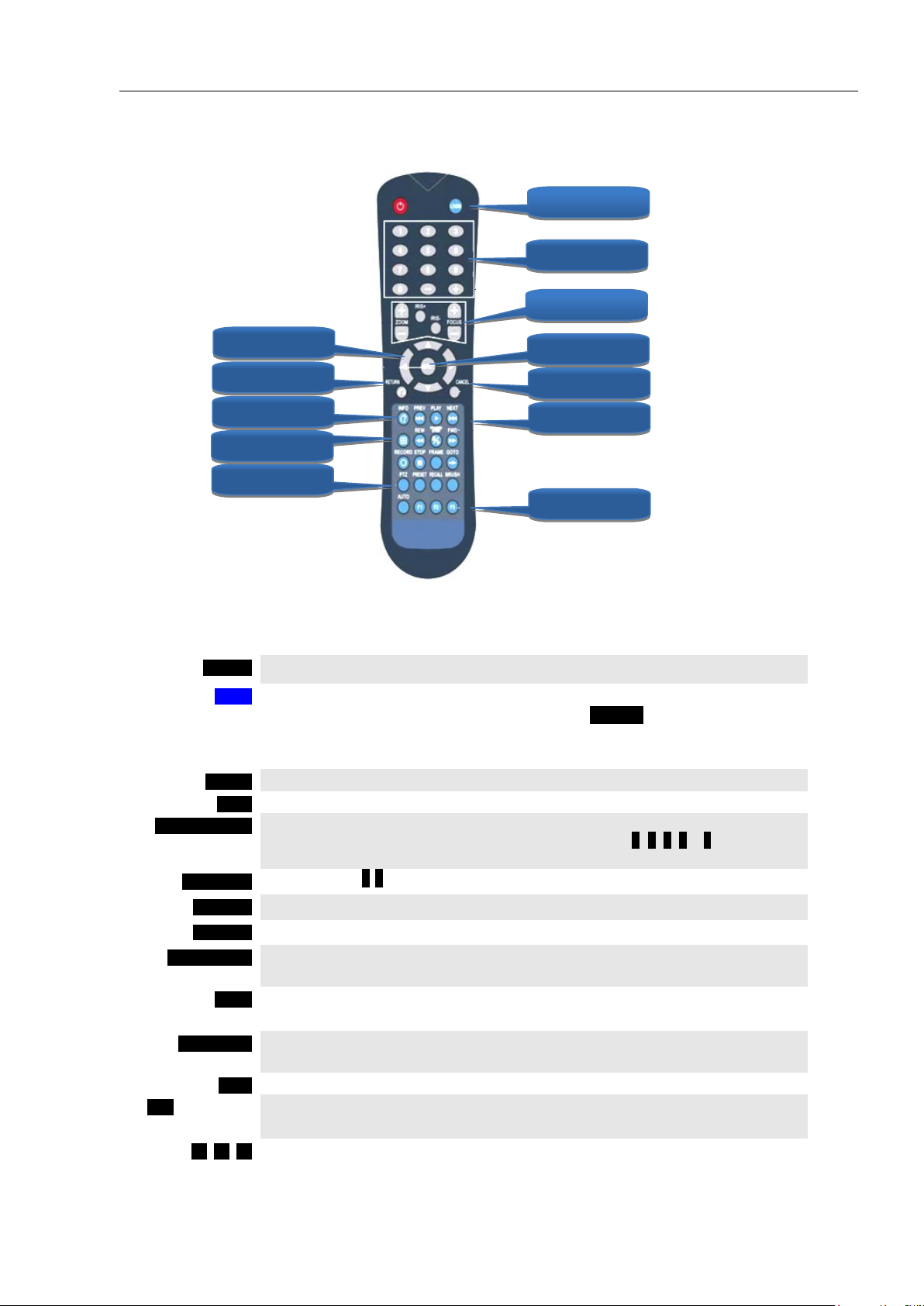
IR REMOTE CONTROL (IRC) FUNCTION KEYS
ENTRY
IRC (Above) function key: Black background with white lettering
SAVE
MDVR Onscreen function key: Blue background with white lettering. A dark blue
background appears it is selected by the IRC. Press ENTER to complete the
function.
LOGIN
Press the LOGIN button to enter the 1.0 USER LOGIN Screen.
INFO
Press to display selected Info Screens overlaid on the Video
SPLITSCREEN
Allows switching between four-screen and single screen views on the LCD
Monitor.Press Screen–Split key to display 5 screens.Press 1, 2, 3, 4or 5to display a
full screen view of the desired camera view
NUMBERS
Press number (0-9) to enter
CANCEL
Press to delete last character entered
RETURN
Press to Return to the previous screen
PAUSE/STEP
Press during the PlayBack mode to Pause and Single Step thru the Video. Press
Direction (arrow) keys to resume normal playback speed
PLAY
Press during Play Back mode to start video playback after you have searched and
selected the video file to review
FORWARD
Press successively to Fast Forward (2X,4X,8X,16X) the video during the Play Back
mode
REW
Press successively to Reverse (2X,4X,8X,16X) the video during Play Back mode
PTZ FUNCTION
KEYS
Press to control various PTZ functions. Including Pan, Tilt, Zoom, Focus, Presets,
etc. Note: PTZ Video Channel view must be selected prior to use
F1, F2, F3
Used for special test functions
LOGIN
NUMBERS
PTZ
CANCEL
PLAYBACK
TEST
PTZ
INFO
DIRECTION
RETURN
ENTER
SPLITSCREEN
Mobilemule™
NOTE: Insert two new AAA alkaline batteries (User supplied) prior to the first use of the IRC.
Function Key Color Code used in the User Guide:
Operation and setup of the User Interface involve onscreen selection and key entry using the IRC:
Page 5
- 5 -
(DATA FIELD)
The MDVR system will post the data. (No User entry)
USER ENTRY FIELD
The User will enter data using the IRC and/or the Virtual
Keyboard will automatically be displayed when needed.
DROP DOWN MENU
The User will select one of the choices offered in the drop down
Menu.
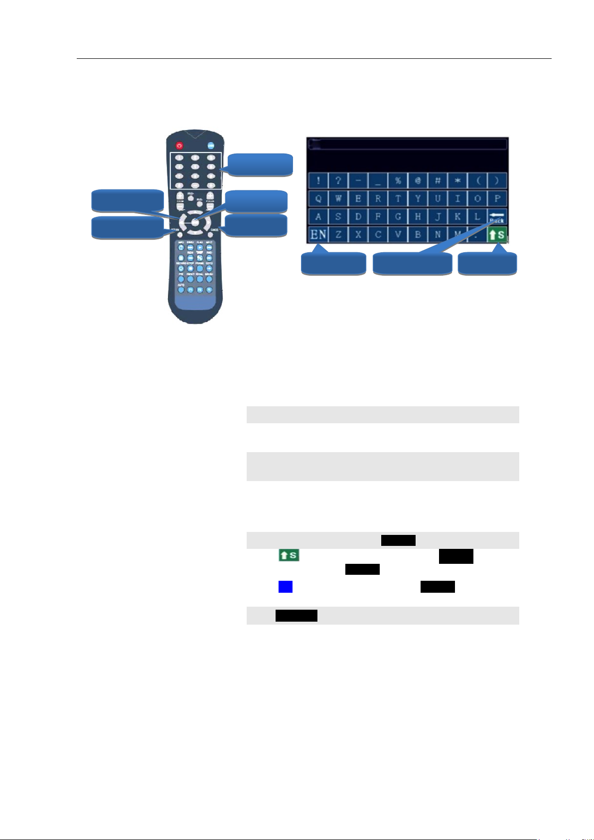
Lower Case Letters and Numbers
Move to the character and press ENTER
Upper Case Letters
Select on the Virtual Keyboard and press.ENTER Select
the character and press ENTER
Switch Languages
Select EN on the Virtual Keyboard. Press ENTER to toggle the
keyboard from English to Chinese and back
Return to Previous Screen
Press RETURN
ENGLISH
SHIFT
BACKSPACE
NUMBER
CANCEL
RETURN
ENTER
DIRECTION
Mobilemule™
IR REMOTE CONTROL USE FOR DATA ENTRY (IRC)
The IR Remote Control (IRC) is used in conjunction with the MDVR Virtual Keyboard to enter alphanumeric data into the MDVR OS selection and data fields. The Virtual Keyboard will automatically appear
as needed. Use the IRC Number Keys for Fields requiring numbers only.
Types of Data Fields used in the GUI:
To enter/delete characters using the Virtual Keyboard and the IRC:
Page 6
- 6 -
TYPICAL UI PAGE LAYOUT
FLOWCHART
(SYSTEM MAP)
YOU ARE HERE
PRIOR
SCREEN
NEXT SCREEN
USAGE
SUMMARY
ITEM NAME
AND USAGE
ACTION BAR
KEYS
SCREEN ID
And NAME
Mobilemule™
Page 7
- 7 -
TITLE BAR
The top blue bar consists of:
ID Unique number to refer to a particular Screen/Menu for support purposes
TITLE Name of the screen for functional reference
ICON AREA
Each ICON relates to specific Sub Menus and Data Screens for entering data and
the settings of various MDVR functions, features and actions
HIGHLIGHTED
ICON
CONTENT
A list of the specific Sub Menus and Data Screens available through the
highlighted Icon for entering data and the settings of various MDVR functions,
features and actions
ENTER
Press to move to the associated Sub Menu or Data Screens
RETURN
Press to return to previous screen
SCREEN ID
ICON AREA
TITLE BAR
HIGHLIGHTED
ICON
HIGHLIGHTED
ICON
CONTENT
TITLE
Mobilemule™
MENU SCREEN LAYOUT
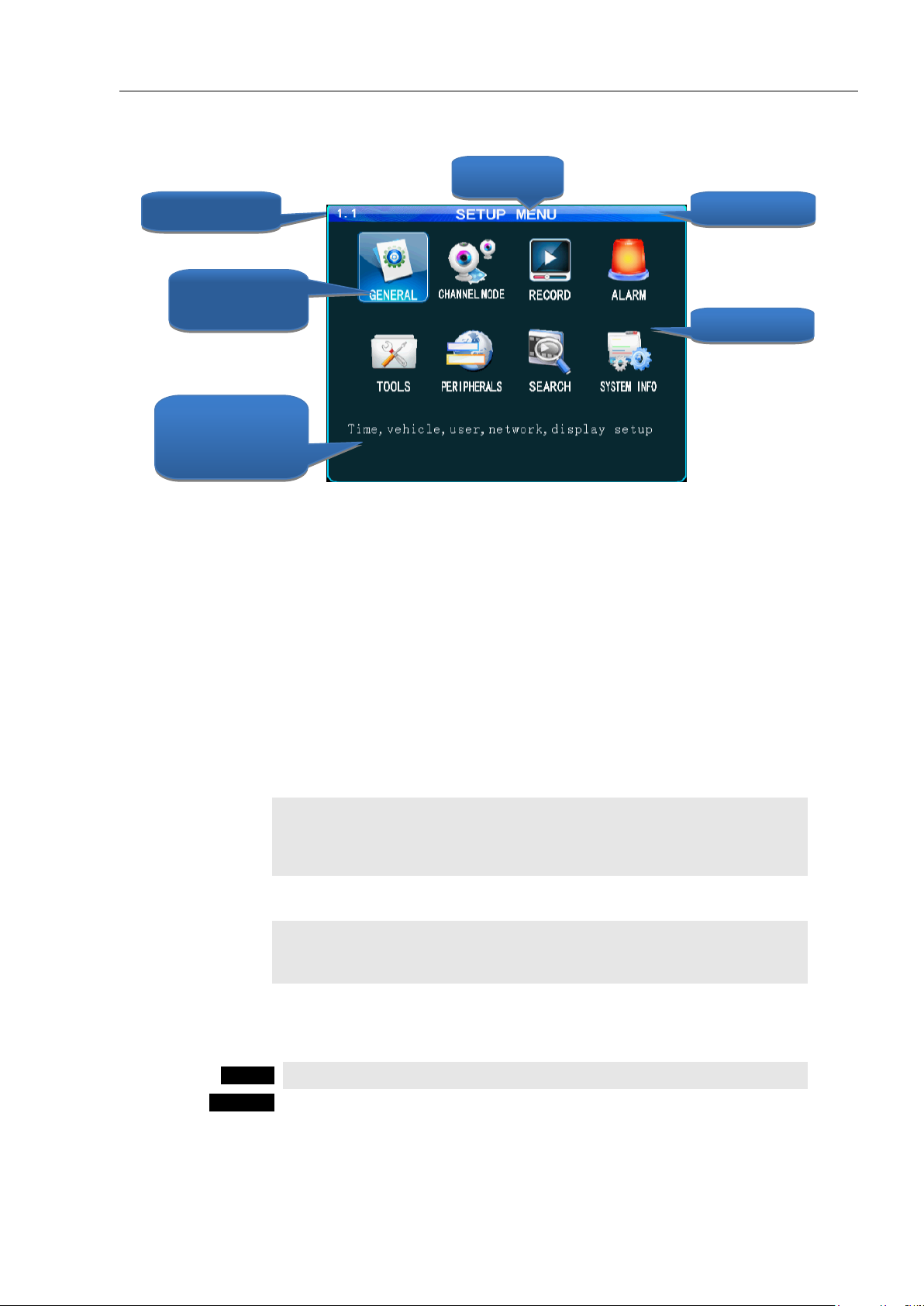
The 1.1 SETUP MENU screen shown above is an example of a typical UI Menu or sub Menu. The Menu
acts as a general gateway to more specific Sub Menus and Data Screens for entering data and the settings of
various MDVR functions, features and actions. In addition, if the User Guide isn’t readily available, the User
may simply move from icon to icon and read the Highlighted Icons Content list to search for access to a
content specific screen.
Use the IR Remote Control (IRC) to move to and highlight the desired icon.
A content description of the highlighted Icon will appear near the bottom of the Menu screen listing the main
topic screens associated with this Icon
There are three major sections:
Use the IRC Direction Keys to highlight the desired ICON, then:
Page 8
- 8 -
TITLE BAR
The top blue bar consists of:
ID Unique number to refer to a particular Screen/Menu for support purposes
TITLE Name of the screen for functional reference
DATA AREA
The data area consists of the fields necessary to setup MDVR options, features and
functions, generate and report monitored activities, etc. For detailed definitions see
the DATA AND ACTION FIELDS page in this User Guide
ACTION BAR
The bottom has the Action Keys (SAVE) necessary to complete the data setup and
entry functions associated with that screen. Select the desired key and press ENTER
ENTER
SCREEN ID
TITLE
TITLE BAR
DATA FIELD
DATA AREA
FIELD NAME
ACTION BAR
ACTION KEYS
Mobilemule™
DATA SCREEN LAYOUT
The Data Screen enables a User with appropriate authorization to view, setup and change the MDVR UI
fields, features and functions.
There are three major sections:
Page 9
- 9 -
DATA ENTRY AND REPORT FIELDS
SYSTEM FILL
( )
Data is automatically entered by the MDVR OS (GPS,
Month, Measurement Unit, Device Reading, etc.)
DATA ENTRY
Data is to be entered by User using the IRC (Numeric only)
or Virtual Keyboard appearing when alphanumeric data
entry is needed
DATA ALERT
A data field background may change color to indicate a
device status change (Red for Alarm, etc.). The User Guide
will define this feature for each affected field
DROP DOWN
Indicated by a ‘Down Arrow’ symbol on the right side of
the field. The User may use the IRC to select the from a
preset list appearing onscreen
DROP DOWN
MENU
Appears when the User selects a Drop Down field using the
IRC. Move the blue highlight (as shown) to the appropriate
entry and press ENTER
DATA
ENTRY
Data is to be entered by User using the IRC (Numeric only)
or Virtual Keyboard appearing when alphanumeric data
entry is needed
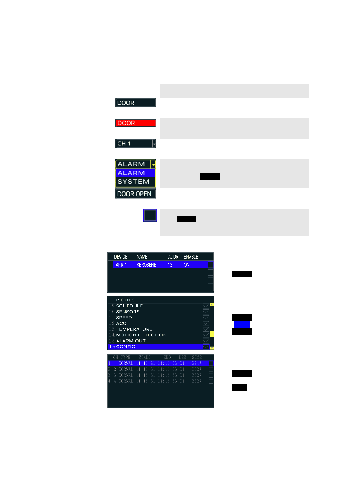
CHECK BOX
Move the blue highlight to the data next to the Check Box.
Press ENTER to select. Different results may occur
depending on the GUI screen settings. The User Guide will
define this feature as necessary. See examples below:
CHECK
AND GO
Single Selection and Go To:
Select one item (Highlight)
Press ENTER
Relevant screen appears
CHECK
LIST
Multiple Selection and Save:
Select one or more items for list
Press ENTER each time
Select SAVE and save list
Press ENTER
Proceeds to relevant screen
CHECK AND
PLAY
Playback List:
Select one or more items
Press ENTER each time
Select video to view
Press PLAY , List will be displayed
at end of video
There are several different types of Data Fields used within the MDVR GUI:
Mobilemule™
Page 10
- 10 -
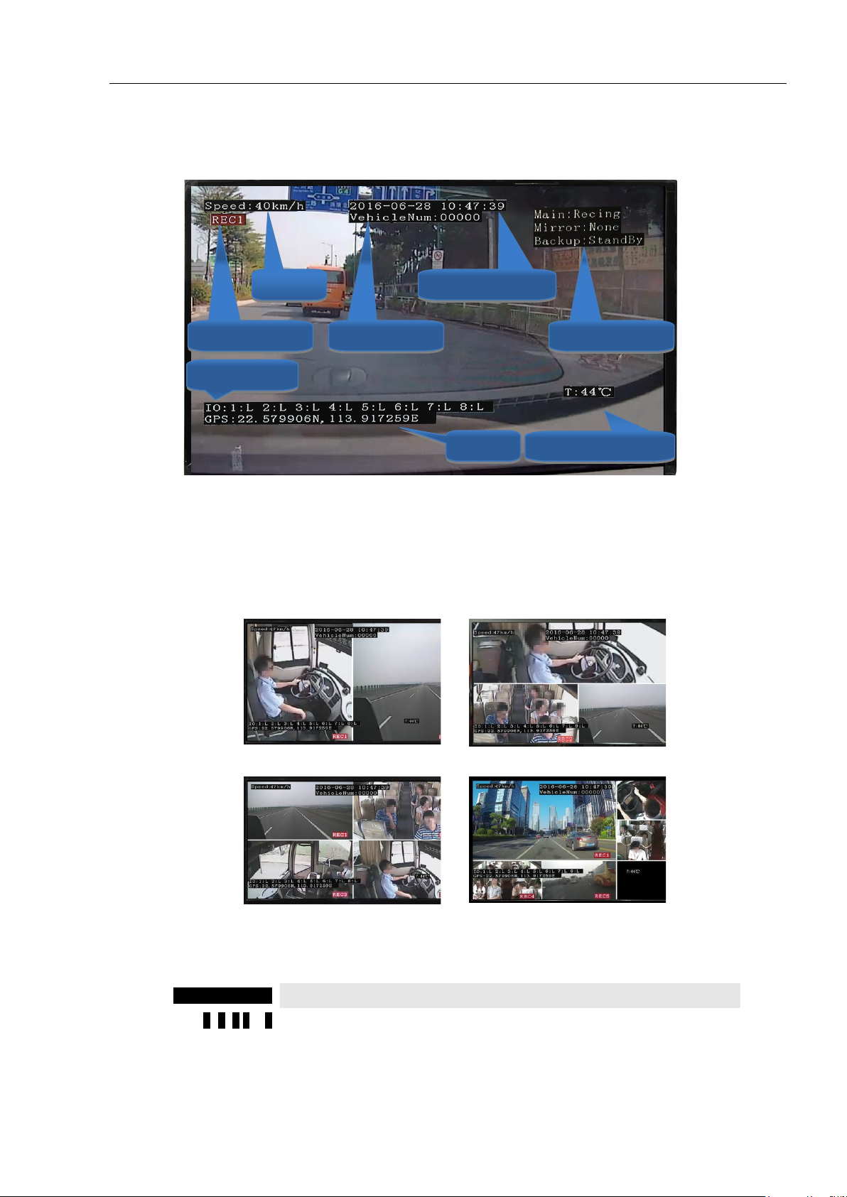
TWO VIEWS
THREE VIEWS
FOUR VIEWS
FIVE VIEWS
SPLITSCREEN
Press to enter SPLIT SCREEN Mode
1, 2, 3,4or 5
Press to display a full screen view of the desired camera view
TEMPERATURE
GPS
I/O STATUS
RECORDING
SPEED
STORAGE
DATE and TIME
VEHICLE ID
Mobilemule™
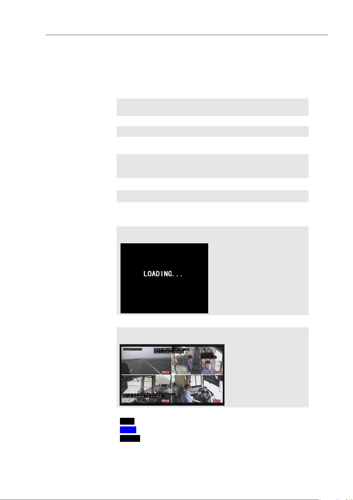
VIDEO SCREEN LAYOUT
Screen View with Data Overlay
Displays current or recorded camera view(s) and/or information (Previously set in the UI) overlaid on video,
including System Messages, Alerts and Status. Requires a properly connected and setup Display Monitor
(Optional)
View up to five MDVR video screens are for real time or playback on a single channel A/V Monitor:
To Change Views:
Page 11
- 11 -
LCD MONITOR
Connected to either the rear I/O Cable Monitor Connector or the A/V Jack on
the Front Panel
SECURITY PANEL
Closed
POWER SOURCE
Connected and MDVR STATUS PANEL PWR indicator (blue) is lit
CHECK POWER
The PWR indicator (blue) will be lit on the front Status Panel to show the
MDVR is receiving power. If the Monitor is powered by the MDVR is may
not display anything until the 0.0 LOADING PAGE appears
INSERT KEY
Insert key into Security Lock located on the front panel
POWER ON
Turn the key counterclockwise 900 from the UNLOCK position
P.O.S.T.
Pre-Operation System Test. It is an automatic and required comprehensive
test of the operational status during startup of the MDVR requiring about 48
seconds to complete.
LOADING SCREEN
The Loading Screen will be displayed during the P.O.S.T. If not, then check
if Monitor is power On and the correct viewing channel set
START UP VIEW
The Startup Screen will be displayed. The camera view(s) will be as set in the
last setup of the MDVR
CHECK STATUS
Use the IRC to verify the operational status of the MDVR:
INFO Press to view 1.8.1 SYSTEM INFO PG 1 OF 2
NEXT Select, then:
ENTER Press to view PG 2.
Mobilemule™
DEVICE START-UP
The following assumes the User has confirmed the MDVR is correctly installed according to the
manufacturers installation instructions and is correctly configured for use:
Pre-check before Startup:
Startup Sequence:
Page 12
- 12 -
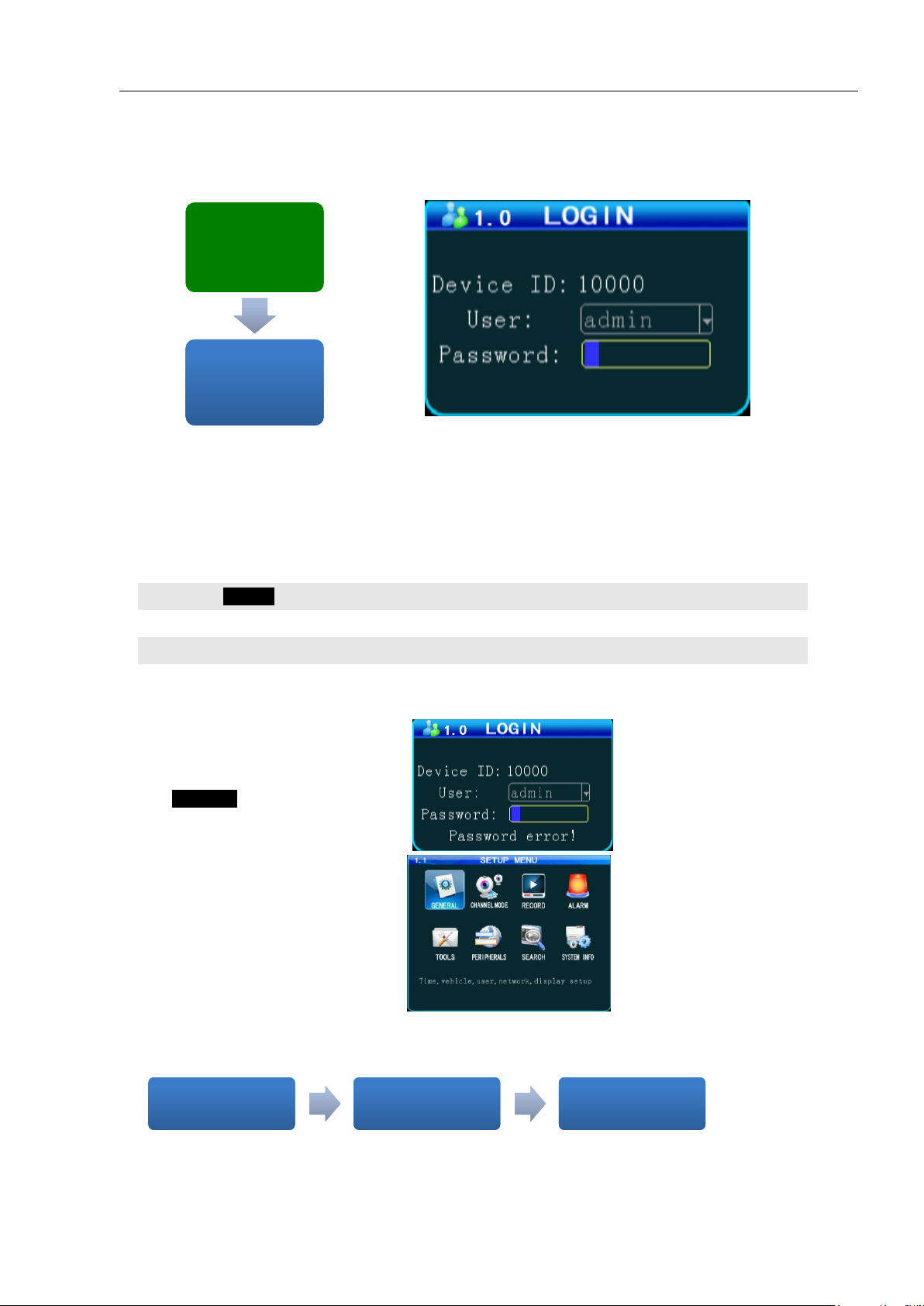
LOGIN
Press
USER
Enter ADMIN
PASSWORD
Enter 888888
Note: If the USER NAME and
PASSWORD do not match, a warning
prompt will appear in below the Password
field to re-enter the correct data. If so,
press RETURN to return to the LOGIN
screen and enter the correct data.
Once the correct User Name and
Password have been entered and accepted
the 1.1 MASTER MENU will appear:
USER LOGIN
1.0
USER LOGIN
1.0
SETUP MENU
1.1
SETUP MENU
1.1
Mobilemule™
1.0 INITIAL LOGIN
The 1.0 USER LOGIN screen is used to provide secure access to the MDVR settings by requiring User
Name and Password entry for access to the MDVR features, functions and settings.
For security purposes change original USER NAME and PASSWORD as soon as possible.
To Login:
To setup the initial User Name and Password go to the 1.1.3.1 PASSWORD SETUP screen:
SETUP MENU 1.1
SETUP MENU 1.1
'GENERAL'
'GENERAL'
GENERAL 1.1.1
GENERAL 1.1.1
'USER SETUP'
'USER SETUP'
PASSWORD SETUP
PASSWORD SETUP
1.1.3.1
1.1.3.1
Page 13
- 13 -
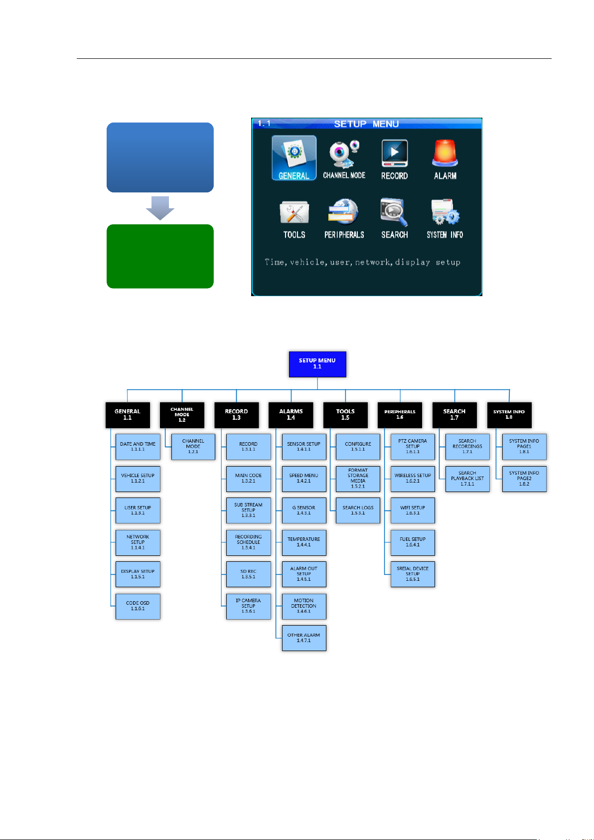
1.1 SETUP MENU
USER LOGIN
1.0
USER LOGIN
1.0
SETUP MENU
1.1
SETUP MENU
1.1
The 1.1SETUP MENU allows access to eight sub menus allowing the User, depending on their System
Access Credentials, to access, search, view and change features or functions:
Mobilemule™
MASTER MENU FLOWCHART
Page 14
- 14 -
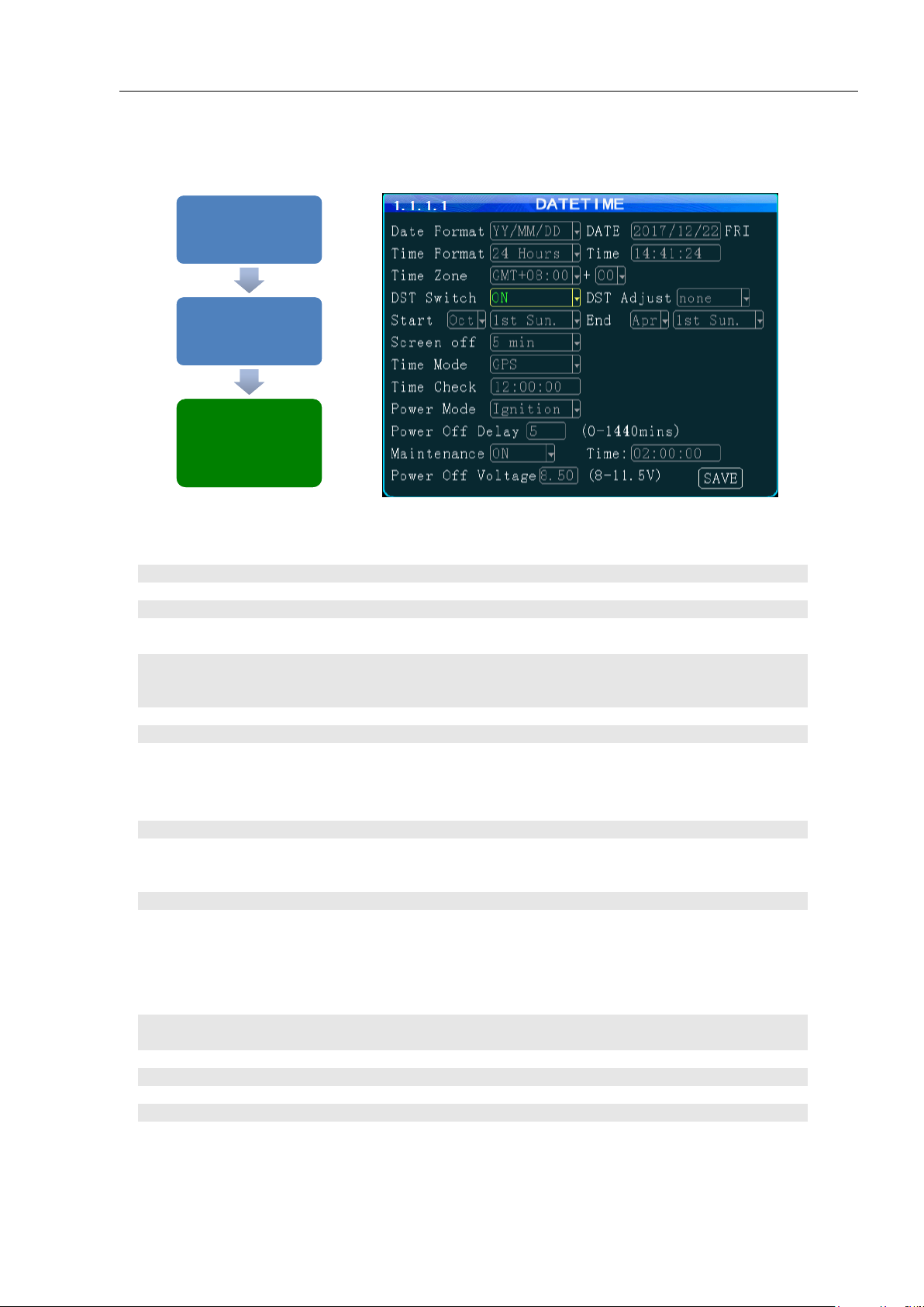
DATE
Enter the current date in the format requested
TIME
Enter the correct local time in the format shown
(DAY)
Auto filled by SYSTEM (No User entry)
DATE FORMAT
Select to one of three possible date formats (Year-Month-Day, Day-MonthYear, Month-Day-Year).
TIME FORMAT
Select one of two Time Formats:
12 HOUR 0 to 12 hours
24 HOUR 0 to 2400 hours
TIME ZONE
Enter the GMT Time Zone setting for your location
PLUS
Select the additional time to add to the GMT time to be accurate locally
TIME MODE
There are two methods of updating the System Time:
MANUAL The User will have to update the System Time.
GPS The GPS system will automatically update the System Time each
time it accesses the International GPS System.
TIME CHECK
Enter time for the MDVR to use GPS to reset onboard time if necessary
MAINT
Select the operational status of this function:
ON The selected functions are ‘On’
OFF The selected functions are ‘Off’
M. TIME
Enter the time the MDVR is to be turned ‘Off’, then ‘On’
DST
Daylight Savings Time. Select from two options:
OFF The default system setting. The User will have to manually change the
System Time to compensate for the DST time changes if applicable.
ON Enables the MDVR to automatically change the System Time based on
Daylight Savings Time (DST)
ADJ
Select the amount of time, if necessary, to be added to the GMT set time for local
accuracy
START
Select the Day DST is to start
MONTH
Select the Month DST is to start
END
Select the Day DST is to end
MONTH
Select the Month DST is to end
SETUP MENU 1.1
'GENERAL'
SETUP MENU 1.1
'GENERAL'
GENERAL 1.1.1
'DATE and TIME'
GENERAL 1.1.1
'DATE and TIME'
DATE and TIME
1.1.1.1
DATE and TIME
1.1.1.1
Mobilemule™
1.1.1.1 DATE AND TIME
The 1.1.1.1 DATE and TIME screen allows the User to select or enter data to set the System Time and
other basic time related properties of the MDVR.
Page 15
- 15 -
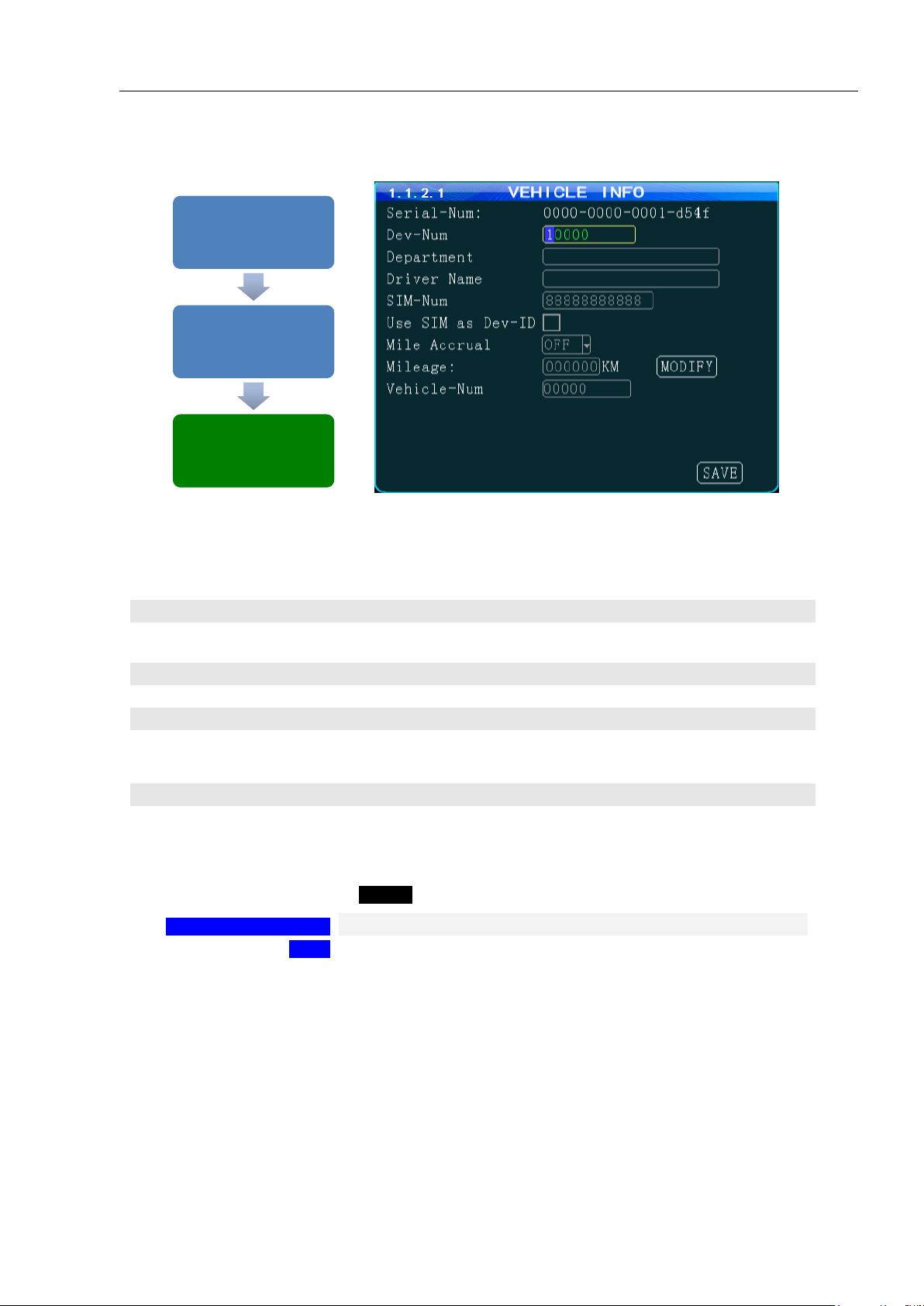
(DEVICE SERIAL ID)
Unique number assigned by factory. (No User entry)
DEVICE NUMBER
Unique number (Up to 7digits) to display on Video Display, be recorded
with the Video files and ID the Vehicle to IVMS
DEPARTMENT
Enter company name (Up to 19 characters)
DRIVER NAME
Drivers name or ID (Up to 19 characters)
SIM NUMBER
Phone number for the MDVR contained SIM Card if installed
MILE ACCRUAL
Select from two ODOMETER options:
ON Odometer will add (accrue) distance traveled based on GPS
OFF Function disabled
ODOMETER(MILEAGE)
Enter starting mileage or kilometers if ACCRUAL function is ‘ON’
LICENSE PLATE
(VEHICLE-NUM)
Enter License Plate characters (Up to 8 characters)
CHANGE ODOMETER
To enter new distance related numbers into the ODOMETER field
SAVE
To save the new settings 1.1.2.1 VEHICLE INFO screen will remain
showing
SETUP MENU 1.1
'GENERAL'
SETUP MENU 1.1
'GENERAL'
GENERAL 1.1.2
'VEHICLE INFO'
GENERAL 1.1.2
'VEHICLE INFO'
VEHICLE INFO
1.1.2.1
VEHICLE INFO
1.1.2.1
Mobilemule™
1.1.2.1 VEHICLE SETUP
The 1.1.2.1VEHICLE INFO screen is used to enter data and enable functions related to the company,
vehicle, driver, mobile phone number and power related operation. The DEVICE NUMBER is the only field
required to have data entered.
Action Bar Keys (Select, then press ENTER):
Page 16
- 16 -
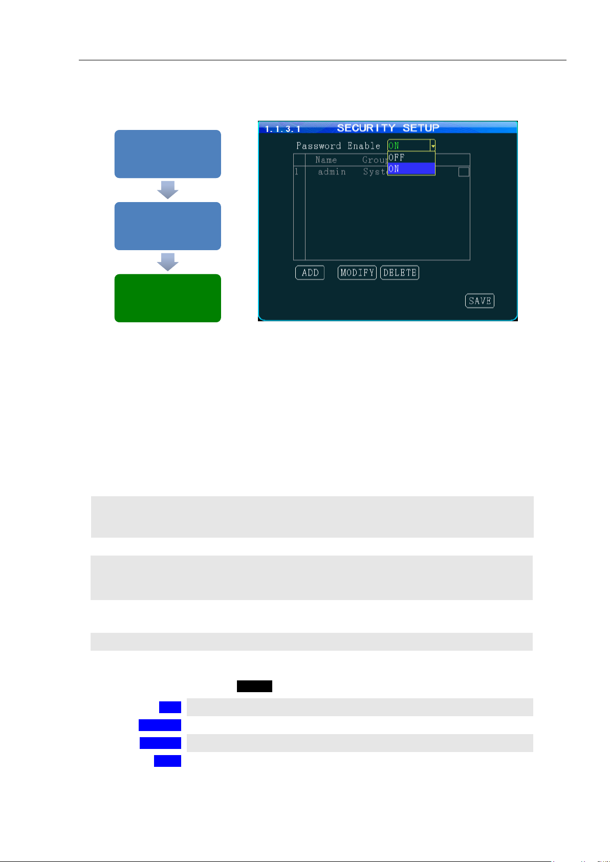
SYSTEM
Select from two options:
Grants unlimited access and change privileges, including creating User Accounts,
Passwords and restricted access Rights
GENERAL
Provides Password, limited access and change Rights
PASSWORD
Select from two options:
ON Password protection is enabled
OFF Password protection is off
OP TIMEOUT
Select time period to elapse prior to automatically logging the User out of the
system
NAME
User Name list
LEVEL
Indicates the System Access Level granted by the ADMIN (No User Entry)
ADD
To Add new User account 1.1.3.1.1 ADD USER screen
MODIFY
To Modify a User settings 1.1.3.1.2 MODIFY USER screen
DELETE
To Delete a User access 1.1.3.1.3 DELETE USER screen
SAVE
To Save the new settings 1.1.3.1 USER SETUP screen will remain
SETUP MENU 1.1
'GENERAL'
SETUP MENU 1.1
'GENERAL'
GENERAL 1.1.3
'USER SETUP'
GENERAL 1.1.3
'USER SETUP'
USER SETUP
1.1.3.1
USER SETUP
1.1.3.1
Mobilemule™
1.1.3.1 USER SETUP
The 1.1.3.1 USER SETUP screen allows setup of two levels of Password protected access to the MDVR UI.
The ADMIN User account must have at least its Password changed first. Use the Action Bar keys to add,
modify or delete User Accounts.
After the initial STSTEM (ADMIN) User Account has at least its Password changed and saved it will be
necessary to login again using the new Password. WARNING: Store the ADMIN Password in a secure
location. If it is lost or forgotten you will have to contact the manufacturer to regain access to the MDVR
OS.
NOTE: For security purposes it is strongly recommended the Administrator setup and enable the
Password function. The default Login: ADMIN Password: 888888
The MDVR Operating System is protected and accessed by two levels of password authority:
Action Bar Keys (Select, then press ENTER):
Page 17
- 17 -
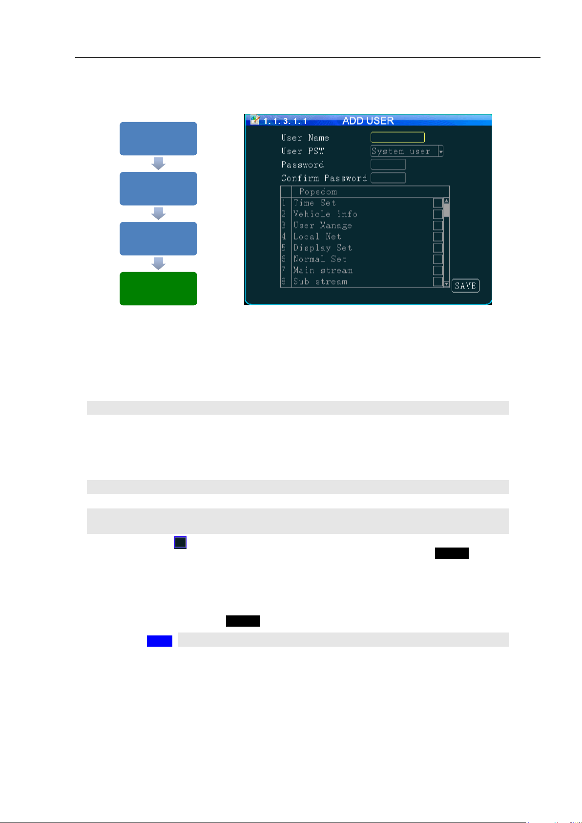
NAME
Enter Users Name
LEVEL (USER PS
W)
Select from two options:
SYSTEM Grants unlimited access and change privileges, including
creating
User Accounts, Passwords and restricted access Rights
GENERAL Provides Password, limited access and change Rights
PASSWORD
Enter Users 6 digit Password (Numbers only)
CONFIRM
Re-enter the same User Password
RIGHTS(POPEDOM)
A title for the list of the User screens allowing setup and change of the
MDVR features. Select as necessary
CHECK BOX
Select the User Access (setup and change) Rights by moving the blue
highlight to the desired Rights Check box and pressing ENTER. Repeat
process until list is complete
SAVE
To save and the 1.1.3.1 USER SETUP screen will appear
SETUP MENU 1.1
'GENERAL'
SETUP MENU 1.1
'GENERAL'
GENERAL 1.1.3
'USER SETUP'
GENERAL 1.1.3
'USER SETUP'
USER SETUP 1.1.3.1
'ADD'
USER SETUP 1.1.3.1
'ADD'
ADD USER 1.1.3.1.1 ADD USER 1.1.3.1.1
Mobilemule™
1.1.3.1.1 ADD USER
The 1.1.3.1.1 ADD USER screen allows SYSTEM level Users to add SYSTEM (total access) or GENERAL
(limited access) level Users for setup and operation of the MDVR User Interface. A total of eight User
accounts are allowed.
After a User Account is entered and saved it will be necessary to login again using the new Password.
To add a User Account:
Confirm the new settings are correct and save the file.
Action Bar Keys (Select, then press ENTER):
Page 18

- 18 -
NAME
Enter Users Name
LEVEL(USER PSW)
Select from two options:
SYSTEM Total system access
GENERAL Limited to specific rights set by the SYSTEM level User
PASSWORD
Enter Users 6 digit Password (Numbers only)
CONFIRM
Re-enter the same User Password
RIGHTS(POPEDOM)
A title for the list of the User screens allowing setup and change of the
MDVR features
CHECK BOX
Select the User Access (setup and change) Rights by moving the blue
highlight to the desired Rights Check box and pressing ENTERto check or
uncheck.Repeat process until list is correct
SAVE
To save and the 1.1.3.1 USER SETUP screen will appear
SETUP MENU 1.1
'GENERAL'
SETUP MENU 1.1
'GENERAL'
GENERAL 1.1.3
'USER SETUP'
GENERAL 1.1.3
'USER SETUP'
USER SETUP 1.1.3.1
'MODIFY'
USER SETUP 1.1.3.1
'MODIFY'
MODIFY USER
1.1.3.1.2
MODIFY USER
1.1.3.1.2
Mobilemule™
1.1.3.1.2 MODIFY USER
The 1.1.3.1.2 MODIFY USER screen allows SYSTEM level Users to change the parameters of an existing
User account.
Once the selected User account is added the 1.1.3.1 USER SETUP screen will appear. To modify another
User account repeat the Modify User account process.
To modify a User Account:
Confirm the new settings are correct and save the file.
Action Bar Keys (Select, then press ENTER):
Page 19

- 19 -
1.1.3.1.3 DELETE USER
NAME
Users Name (No User entry)
LEVEL(GROUP)
Users Access Level:
SYSTEM Total system access
GENERAL Limited to specific rights set by the SYSTEM level User
CHECK BOX
Select the User Account to be deleted by moving the blue highlight to the desired
Rights Check box and pressing ENTER
DELETE
To delete User account and the 1.1.3.1 USER SETUP screen will appear
SETUP MENU 1.1
'GENERAL'
SETUP MENU 1.1
'GENERAL'
GENERAL 1.1.3
'USER SETUP'
GENERAL 1.1.3
'USER SETUP'
SETUP SETUP 1.1.3.1
'DELETE'
SETUP SETUP 1.1.3.1
'DELETE'
DELETE USER
1.1.3.1.3
DELETE USER
1.1.3.1.3
The 1.1.3.1.3 DELETE USER screen allows a SYSTEM level User to delete an existing User account.
Mobilemule™
If a User account is deleted by mistake, it will have to be re-entered using the 1.1.3.1.1 ADD USER screen.
Once the selected User account is deleted the 1.1.3.1 USER SETUP screen will appear. To delete another
account repeat the Delete User account process.
Action Bar Keys (Select, then press ENTER):
Page 20

- 20 -
IP ADDRESS
Enter in standard format (000.000.000.000)
NETMASK
Enter in standard format (000.000.000.000)
GATEWAY
Enter in standard format (000.000.000.000)
MAC ADDRESS
The Modem will display the MDVRs MAC Address. It can be User edited
NET MODE
Select one of two options:
DOMAIN When selected, the DOMAIN and DNS Fields will appear
IP When selected, the SERVER IP Field will appear
DOMAIN NAME
(30 Characters)Appears only when DOMAIN is selected in the above field
DNS
Appears only when DOMAIN is selected in the NET MODE field
SERVER ADDRESS
Appears only when IP is selected in the NET MODE field
CONTROL PORT
(6 digits) Contact IVMS SysOp for this field entry
INTERCOM IP
Contact IVMS SysOp for this field entry. This feature requires the INTERCOM
Kit (Optional)
INTERCOM PORT
(6 digits)Contact IVMS SysOp for this field entry. This feature requires the
INTERCOM Kit (Optional)
SAVE
To saveand activate the new settings
SETUP MENU 1.1 '
'GENERAL'
SETUP MENU 1.1 '
'GENERAL'
GENERAL 1.1.4
'NETWORK'
GENERAL 1.1.4
'NETWORK'
NETWORK SETUP
1.1.4.1
NETWORK SETUP
1.1.4.1
Mobilemule™
1.1.4.1 NETWORK SETUP (3G/4G/WIFI Option Required)
The 1.1.4.1 NETWORK SETUP function enables the User to setup a 3G/4G/WIFI based, full duplex
(bi-directional), communication between the MDVR and the Central Monitoring Service (IVMS)
(optional) for real time, remote monitoring, setup, speed, etc. To utilize these functions, a compatible
Internal or External WIFI Modem or 3G/4G must be connected and enabled. The Internal Modem must be
ordered and installed by the factory. The External Modem is available as an option. Contact your IVMS
SysOp(IT) for the data to enter below.
Action Bar Keys (Select, then press ENTER):
Page 21

- 21 -
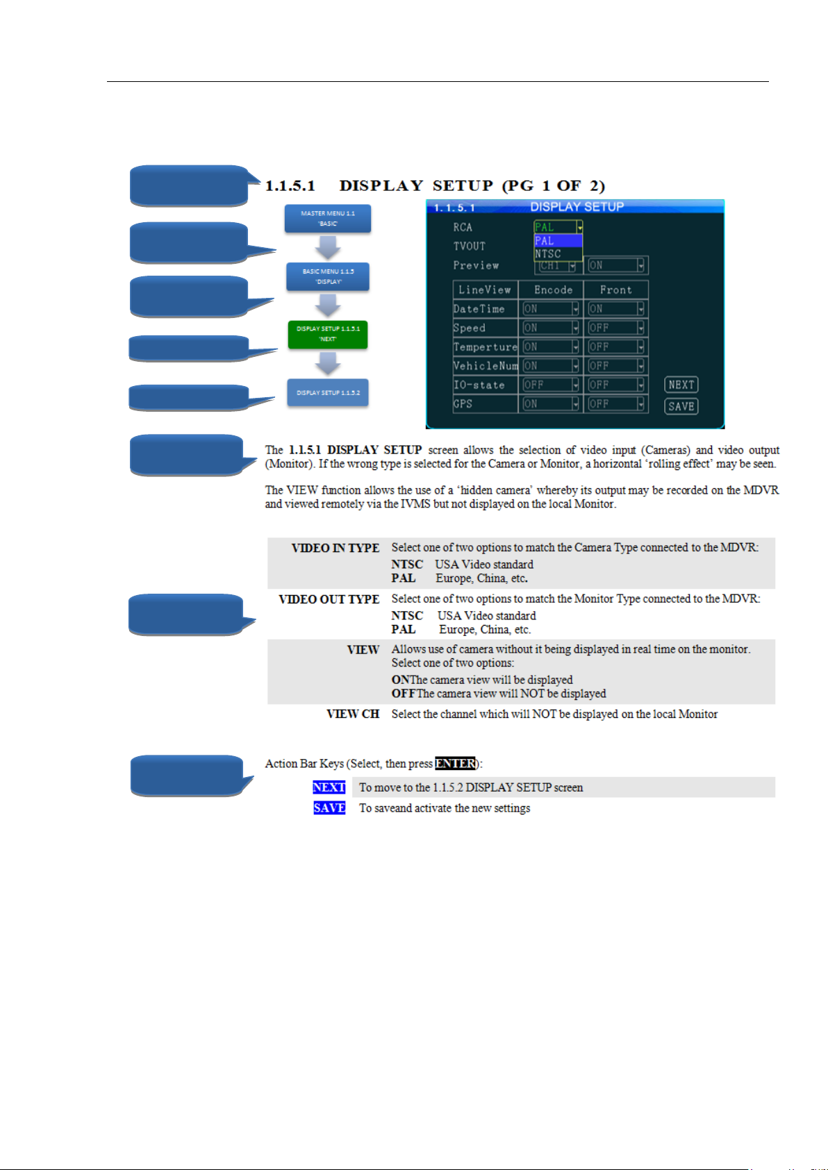
1.1.5.1 DISPLAY SETUP (PG 1 OF 2)
VIDEO IN TYPE
Select one of two options to match the Camera Type connected to the MDVR:
NTSC USA Video standard
PAL Europe, China, etc.
VIDEO OUT TYPE
Select one of two options to match the Monitor Type connected to the MDVR:
NTSC USA Video standard
PAL Europe, China, etc.
VIEW
Allows use of camera without it being displayed in real time on the monitor.
Select one of two options:
ON The camera view will be displayed
OFF The camera view will NOT be displayed
VIEW CH
Select the channel which will NOT be displayed on the local Monitor
NEXT
To move to the 1.1.5.2 DISPLAY SETUP screen
SAVE
To save and activate the new settings
SETUP MENU 1.1
'GENERAL'
SETUP MENU 1.1
'GENERAL'
GENERAL 1.1.5
'DISPLAY'
GENERAL 1.1.5
'DISPLAY'
DISPLAY SETUP 1.1.5.1
'NEXT'
DISPLAY SETUP 1.1.5.1
'NEXT'
DISPLAY SETUP 1.1.5.2 DISPLAY SETUP 1.1.5.2
Mobilemule™
The 1.1.5.1 DISPLAY SETUP screen allows the selection of video input (Cameras) and video output
(Monitor). If the wrong type is selected for the Camera or Monitor, a horizontal ‘rolling effect’ may be seen.
The VIEW function allows the use of a ‘hidden camera’ whereby its output may be recorded on the MDVR
and viewed remotely via the IVMS but not displayed on the local Monitor.
Action Bar Keys (Select, then press ENTER):
Page 22

- 22 -
1.1.5.2 DISPLAY SETUP (PG 2 OF 2)
EMBED
Data is overlaid and becomes a permanent part of the video
OVERLAY
Data is displayed overlaid on the video but not saved as integral part of the video
DAY/TIME
Select from two options each for EMBED and OVERLAY:
ON
OFF
SPEED
Select from two options each for EMBED and OVERLAY:
ON
OFF
INT TEMP
Select from two options each for EMBED and OVERLAY:
ON
OFF
VEH ID
Select from two options each for EMBED and OVERLAY:
ON
OFF
I/O STATUS
Select from two options each for EMBED and OVERLAY:
ON
OFF
GPS COORD
Select from two options each for EMBED and OVERLAY:
ON
OFF
SD STATUS
Select from two options for OVERLAY:
ON
OFF
HD STATUS
Select from two options for OVERLAY:
ON
OFF
SAVE
To save and activate the new settings
SETUP MENU 1.1
'GENERAL'
SETUP MENU 1.1
'GENERAL'
GENERAL 1.1.5
'DISPLAY'
GENERAL 1.1.5
'DISPLAY'
DISPLAY SETUP 1.1.5.1
'NEXT'
DISPLAY SETUP 1.1.5.1
'NEXT'
DISPLAY SETUP 1.1.5.2 DISPLAY SETUP 1.1.5.2
Mobilemule™
The 1.1.5.1 DISPLAY SETUP screen allows to the User to select Embed and/or Overlay options for the
fields listed on the screen.
Action Bar Keys (Select, then press ENTER):
Page 23

- 23 -
ENABLE
Select from two options:
ON Enable Video channel OSD
OFF Disable video channel OSD
CH-X.
CH 1 – 5
XPOS
(0 to 99) Abscissa position parameters.
YPOS
(0 to 99) Ordinate position parameters
CHANNE
L NAME
Character overlay channel name :
Can be described according to the installation location, the default CH1-CH5,
SAVE
To save and activate the new settings
SETUP MENU 1.1 '
'GENERAL'
SETUP MENU 1.1 '
'GENERAL'
GENERAL 1.1.6
'CODE OSD'
GENERAL 1.1.6
'CODE OSD'
CODE OSD SETUP
1.1.6.1
CODE OSD SETUP
1.1.6.1
Mobilemule™
1.1.6.1 CODE OSD
The 1.1.6.1 CODE OSD screen provides the function of character overlay for each video channel,
which determines the display position of the characters according to the abscissa and ordinate values. Note:
The CH 5 is used for IP cameras connected to the RJ 45 connector, and the IP camera can also set the
character overlay function individually.
Action Bar Keys (Select, then press ENTER):
Page 24

- 24 -
1.2.1 CHANNEL MODE
CAMERA MIX
Determine the types of cameras connected to the MDVR
SELECT
Select (Blue highlight) the group of cameras matching the cameras connected
to the MDVR
CHECK BOX
Press ENTER to select the checked group
RESTART
Select SAVE, then press ENTER and THE SYSTEM WILL RESTART in
order to recognize the new camera mix
GO TO
AFTER THE MDVR RESTARTS go to the 1.3.5.1 IP CAMERA SETUP
screen
MIX OPTION 1
Only AHD Cameras may be connected to Camera Input Channels 1, 2, 3, 4
MIX OPTION 2
Only ANALOG Cameras may be connected to Camera Input Channels 1, 2, 3, 4
MIX OPTION 3
AHD Cameras are limited to connection to Camera Input Channels 1 and 2
ANALOG Cameras are limited to connection to Camera Input Channels 3 and 4
MIX OPTION 4
AHD Cameras may be connected to Camera Input Channels 1, 2, 3, 4
IP Camera may be connected to the RJ45 Port
MIX OPTION 5
ANALOG Cameras may be connected to Camera Input Channels 1, 2, 3, 4
IP Camera may be connected to the RJ45 Port
SETUP MENU 1.2
'CHANNEL MODE'
SETUP MENU 1.2
'CHANNEL MODE'
CHANNEL MODE 1.2 CHANNEL MODE 1.2
CAMERA MODE 1.2.1 CAMERA MODE 1.2.1
Mobilemule™
The 1.2.1 CHANNEL MODE screen allows the selection of one of four camera groups to match the variety
of AHD, Analog and IP Cameras which may be connected to the MDVR Camera inputs.
The MDVR must be restarted each time a new combination of cameras is connected using these five steps:
Select one of five options:
Page 25

- 25 -
RECORD TYPE
VIDEO(NORMAL) Records video per settings in 1.3.2.1 MAIN CODE
I FRAME Saves storage space but results in choppy video playback
RECORD MODE
AUTO MDVR automatically starts up in Recording Mode
TIMER Recording is controlled by settings in 1.3.4.1
RECORD PLAN
ALARMMDVR starts Recording Mode when triggered
PACKET
TIME(REC
LENGTH)
Sets the max time a recording file can remain open.
Select from5,15, 30, 45, 60 minutes (Shorter offers more protection)
OVERWRITE
Select whether to overwrite earlier recorded data on the storage media other than
the files protected by the ALM FILE LOCK setting:
ON Continuously record files as new files replace older ones
after the storage media is full
OFF MDVR will continue to write to the storage media until full
and then stop recording
PRERECORD
Adds video from time previous to the alarmed triggered recording. Enter the
time in seconds for the length of the added files
POST
RECORD(ALM
DELAY)
Enter the time in Seconds to continue recording after being triggered
ALM OUT
Enter the time in seconds (5 – 255) for the ALM indicator on the MDVR front
panel and the device connected to the SENSOR OUTPUT to be activated
ALM FILE
LOCK
Enter the number of days to prevent an alarm designated file from being
overwritten
ENCRYPT VID
Select from two options:
ON Provides encryption to maintain file privacy.
OFF No protection
ENCRYPT KEY
Enter the Encryption Key to be used in the PLAYBACK program
DISPLAY
Select the number of video channels (CH 1 – 5) to be displayed on the Monitor
AUD OUT VOL
Select the Audio Output volume level to the Monitor
ACC/REC OFF
Allows selection of the camera view(s) which WILL NOT be recorded when
the vehicle is in the ACC mode:
NONE Every camera view will be recorded per preset parameters
ALL Every cameras view will not be recorded
CH (Select) Choose a single specific camera view to not be recorded
UPLOAD
UPLOAD + RECORD If Encryption set IVMS cannot open file.
UPLOAD ONLY
SETUP MENU 1.3
'RECORD'
SETUP MENU 1.3
'RECORD'
RECORD MENU 1.3.1
'RECORD'
RECORD MENU 1.3.1
'RECORD'
RECORD SETUP
1.3.1.1
RECORD SETUP
1.3.1.1
Mobilemule™
1.3.1.1 RECORD SETUP
The 1.3.1.1 RECORD SETUP screen is one of the most used setup screens concerning file storage criteria.
Page 26

- 26 -
ENABLE
Select from two options:
ON Enable Video channel recording
OFF Disable video channel recording
RES.
CH 1 – 4 D1, HD1, CIF, 960H
CH 5 720P, 1080P
The higher the chosen resolution, the more storage space will be required and the video will
be more detailed.
FPS
(1 to 30) Select the Frames Per Second to be recorded. The higher the number, the closer to
real time fluidity (30 FPS for NTSC and 25 FPS for PAL settings) action will be recorded.
The higher the setting the more storage space will be required for the file.
QUALITY
(1 to 8) Enter the record resolution setting desired with 1 being the highest quality. A higher
quality setting will require more file storage space, but yield a more detailed video.
AUDIO
Select from two options:
ON Enable audio recording (If selected camera channel has a microphone connected)
OFF Disable audio recording of an audio Pickup equipped video source
SAVE
To save and the 1.1.3.1 USER SETUP screen will appear
SETUP MENU 1.3
'RECORDING'
SETUP MENU 1.3
'RECORDING'
RECORD 1.3.2
'MAIN CODE'
RECORD 1.3.2
'MAIN CODE'
MAIN CODE
1.3.2.1
MAIN CODE
1.3.2.1
Mobilemule™
1.3.2.1 MAIN CODE
The 1.3.2.1 MAIN CODE screen provides the ability to configure each of the MDVRs five video channels
to provide the optimum balance of Video Type, Frames per Second (FPS), Resolution and Quality while
ensuring the maximum file storage is achieved on the installed storage media. NOTE: CH 5 is for the IP
Camera connected to the RJ 45 connector.
Action Bar Keys (Select, then press ENTER):
Page 27

- 27 -
SAVE
To save and activate the new settings
SETUP MENU 1.3
'RECORD'
SETUP MENU 1.3
'RECORD'
RECORD 1.3.3
'SUB-STREAM'
RECORD 1.3.3
'SUB-STREAM'
SUB-STREAM
SETUP 1.3.3.1
SUB-STREAM
SETUP 1.3.3.1
Mobilemule™
1.3.3.1 SUB – STREAM SETUP
The 1.3.3.1SUB-STREAM SETUP Menu allows the User to achieve a balance between speed of data
transmission and the video resolution (clarity). The uploading (transmission) of the video files from the
MDVR to another location by WIFI or 3G cellular communication networks is limited by Bandwidth. Sub-
stream settings refer to the choices being made when uploading the MDVR recorded files to another
location such as to the IVMS Server over 3G. The User must choose a balance of speed and resolution.
Higher resolution files require a longer transmission time yet yield clearer video. Whereas faster transfer
rates are a result of sending lower resolution video files quickly, but yield less detailed videos for replay. In
some cases the larger file size will overwhelm the systems available bandwidth and result in intermittent,
slow or error laden file transfers. As shown in the chart below the sub-stream settings are related to whether
the video displayed on the IVMS platform is clear and smooth. Of course, the most important factor for
network transmission is the up and down rate of the local network broadband. Video resolution can be set as
CIF and QCIF.
The corresponding relationship between bit rate setting and the frame rate changing is shown as below, the
bit rate set here is the transmission rate of a channel.
The frame rate setting is changed according to the corresponding bit rate change; it can be set as bit rate
128,frame rate 8 in default. This setting is the current one that can guarantee fluency as well as a certain
resolution when the cellular network transmits audio and video,but you can set this based on your own
network situation, if under good enough network bandwidth, it can be set higher frame rate and bit rate and it
can also be set automatically.
Action Bar Keys (Select, then press ENTER):
Page 28

- 28 -
1.3.4.1 RECORDING SCHEDULE
PERIOD
Select and enter the recording time setting periods per day:
1 First recording time period for the day
2 Second recording period for the day
EVERY DAY
Sets the same schedule for every day of the week. Do not enter time in any other days
MONDAY
TUESDAY
WEDNESDAY
THURSDAY
FRIDAY
SATURDAY
SUNDAY
Set each individual days schedule independently
START
Enter Start recording time in 24 Hour format
END
Enter End recording time in 24 Hour format
SAVE
To save and activate the new settings
SETUP MENU 1.3
'RECORD'
SETUP MENU 1.3
'RECORD'
RECORD 1.3.4
'RECORDING
SCHEDULE'
RECORD 1.3.4
'RECORDING
SCHEDULE'
RECORDING
SCHEDULE
1.3.4.1
RECORDING
SCHEDULE
1.3.4.1
Mobilemule™
The 1.3.4.1 RECORDING SCHEDULE screen allows the MDVR to be programmed to record for
two periods per day. The default setting is to record whenever the MDVR is operating. It can also be set to
use the same recording periods every day or each day can be set to record using a schedule specific to that
day.
NOTE: A recording schedule problem may occur if the schedule set above differs from the 1.1.1.1 DATE
AND TIME SETUP screen when POWER MODE is set to TIMER and the POWER ON, OFF settings
conflict or overlap.
Action Bar Keys (Select, then press ENTER):
Page 29
- 29 -
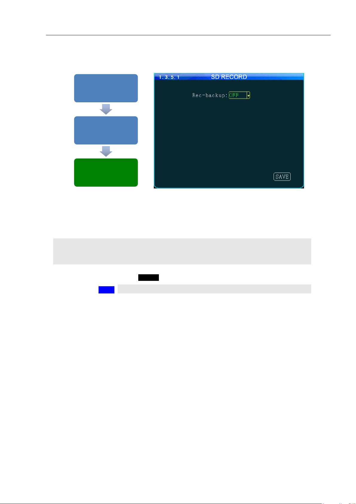
1.3.5.1 SD CARD RECORDING SETUP
ENABLE(REC-
BACKKUP)
Select from two options:
ON SD Card is ready to record
OFF SD Card is NOT ready to record
SAVE
To save and activate the new setting
SETUP MENU 1.3
'RECORD'
SETUP MENU 1.3
'RECORD'
RECORD 1.3.5
'SD REC'
RECORD 1.3.5
'SD REC'
SD CARD RECORDING
1.3.5.1
SD CARD RECORDING
1.3.5.1
Mobilemule™
The 1.3.5.1 SD CARD RECORDING screen allows the User to enable the MDVR to save recorded files to
the SD Card. Enabling SD Card Recording does not effect the settings for the HDD.
Action Bar Keys (Select, then press ENTER):
Page 30

- 30 -
1.3.6.1 IP CAMERA SETUP
GO TO
1.2.1 CHANNEL MODE screen and complete the CHANNEL setup. The
MDVR will restart in order to properly recognize the addition of the IP Camera
RETURN
To this screen and complete the addition, modification or deletion of the IP
Camera as necessary
ADD
Select ADD, then press ENTER to move to the 1.3.6.1.1 ADD IP CAMERA
screen
IPC CHANNEL
Auto fill (No User entry)
IP ADDRESS
Auto fill (No User entry)
PORT
Auto fill (No User entry)
ADD
To Add new IP Camera 1.3.6.1.1 ADD IP CAMERA screen
MODIFY
To Modify IP Camera 1.3.6.1.2 MODIFY IP CAMERA screen
DELETE
To Delete IP Camera 1.3.6.1.3 DELETE IP CAMERA screen
SETUP MENU 1.3
'RECORD'
SETUP MENU 1.3
'RECORD'
RECORD 1.3.6 'IP
CAMERA'
RECORD 1.3.6 'IP
CAMERA'
IP CAMERA
1.3.6.1
IP CAMERA
1.3.6.1
Mobilemule™
The 1.3.6.1 IP CAMERA SETUP screen allows the detection and setup of an IP Camera using the MDVR
RJ 45 Port. Once an IP Camera is connected to the RJ 45 Port it is automatically discoverable by the MDVR.
Initial IP Camera setup:
IP Camera Data Fields:
Action Bar Keys (Select, then press ENTER):
Page 31

- 31 -
READ
Read and understand the IP Camera User Guide included with the product
CONFIGURE
Setup the camera parameters as necessary
CONNECT
Plug the IP Camera cable from the camera into the RJ45 jack on the rear of the
MDVR
SEARCH
Select, then:
ENTER
Press. The MDVR will search for a correctly connected IP Camera and will auto
fill and display the units Channel, IP Address and Port. If no IP Camera is
detected a ‘NO IP CAMERA FOUND’ message will appear on screen
USER NAME
Enter User Name
PASSWORD
Enter Users 6 digit Password (Numbers only)
IPC CHANNEL
Auto fill (No User entry)
IP ADDRESS
Auto fill (No User entry)
PORT
Auto fill (No User entry)
SEARCH
To search for connected IP Camera
SAVE
To save and the 1.3.6.1 IP CAMERA SETUP screen will appear
SETUP MENU 1.3
'RECORD'
SETUP MENU 1.3
'RECORD'
RECORD 1.3.6
'IP CAMERA'
RECORD 1.3.6
'IP CAMERA'
IP CAMERA 1.3.6.1.1
'ADD'
IP CAMERA 1.3.6.1.1
'ADD'
ADD IP CAMERA
1.3.6.1.1
ADD IP CAMERA
1.3.6.1.1
Mobilemule™
1.3.6.1.1 ADD IP CAMERA
The 1.3.6.1.1 ADD IP CAMERA screen allows authorized Users to add and search for connected IP
Cameras. The IPC to be added needs to be the same as the MDVR's IP gateway
To add an IP Camera:
IP Camera Data Fields:
Confirm the new settings are correct and save the file.
Action Bar Keys (Select, then press ENTER):
Page 32

- 32 -
1.3.6.1.2 MODIFY IP CAMERA
CHANNEL
Auto fill (No User entry)
ASSIGNED IP
Auto fill (No User entry)
PORT
Change as necessary
USER NAME
Enter User Name
PASSWORD
Enter Users 6 digit Password (Numbers only)
SAVE
To save and the 1.3.6.1 IP CAMERA SETUP screen will appear
SETUP MENU 1.3
'RECORD'
SETUP MENU 1.3
'RECORD'
RECORD 1.3.6
'IP CAMERA'
RECORD 1.3.6
'IP CAMERA'
IP CAMERA 1.3.6.1
'MODIFY'
IP CAMERA 1.3.6.1
'MODIFY'
MODIFY IP
CAMERA 1.3.6.1.2
MODIFY IP
CAMERA 1.3.6.1.2
Mobilemule™
The 1.3.6.1.2 MODIFY IP CAMERA screen allows authorized Users to change the parameters of an
existing IP Camera. This is useful for filling in the data fields when the auto fill feature is not available.
IP Camera Data Fields:
Confirm the new settings are correct and save the file.
Action Bar Keys (Select, then press ENTER):
Page 33

- 33 -
1.3.6.1.3 DELETE IP CAMERA
CANAEL
Cancel deletion. Select and press ENTER to cancel deletion and return to the 1.3.6.1
IP CAMERA SETUP screen
OK
Delete IP Camera. Select and press ENTER to delete the IP Camera from the system
and return to the 1.3.6.1 IP CAMERA SETUP screen
CANAEL
To Cancel deletion and return to the 1.3.6.1 IP CAMERA SETUP screen
OK
To Delete the IP Camera from the system and return to the 1.3.6.1 IP CAMERA
SETUP screen
SETUP MENU 1.3
'RECORD'
SETUP MENU 1.3
'RECORD'
RECORD 1.3.6
'IP CAMERA'
RECORD 1.3.6
'IP CAMERA'
IP CAMERA 1.3.6.1
'DELETE'
IP CAMERA 1.3.6.1
'DELETE'
DELETE IP
CAMERA 1.3.6.1.3
DELETE IP
CAMERA 1.3.6.1.3
The 1.3.6.1IP CAMERA SETUP screen allows an authorized User to delete an existing IP Camera.
Mobilemule™
After DELETE has been selected and entered, a System Warning Message ‘DELETE THIS IP CAMERA?’
will be appear onscreen.
Select from two options:
Once the selected IP Camera is deleted or the deletion cancelled the 1.3.6.1 IP CAMERA SETUP screen
will appear with the System Warning.
Action Bar Keys (Select, then press ENTER):
Page 34
- 34 -
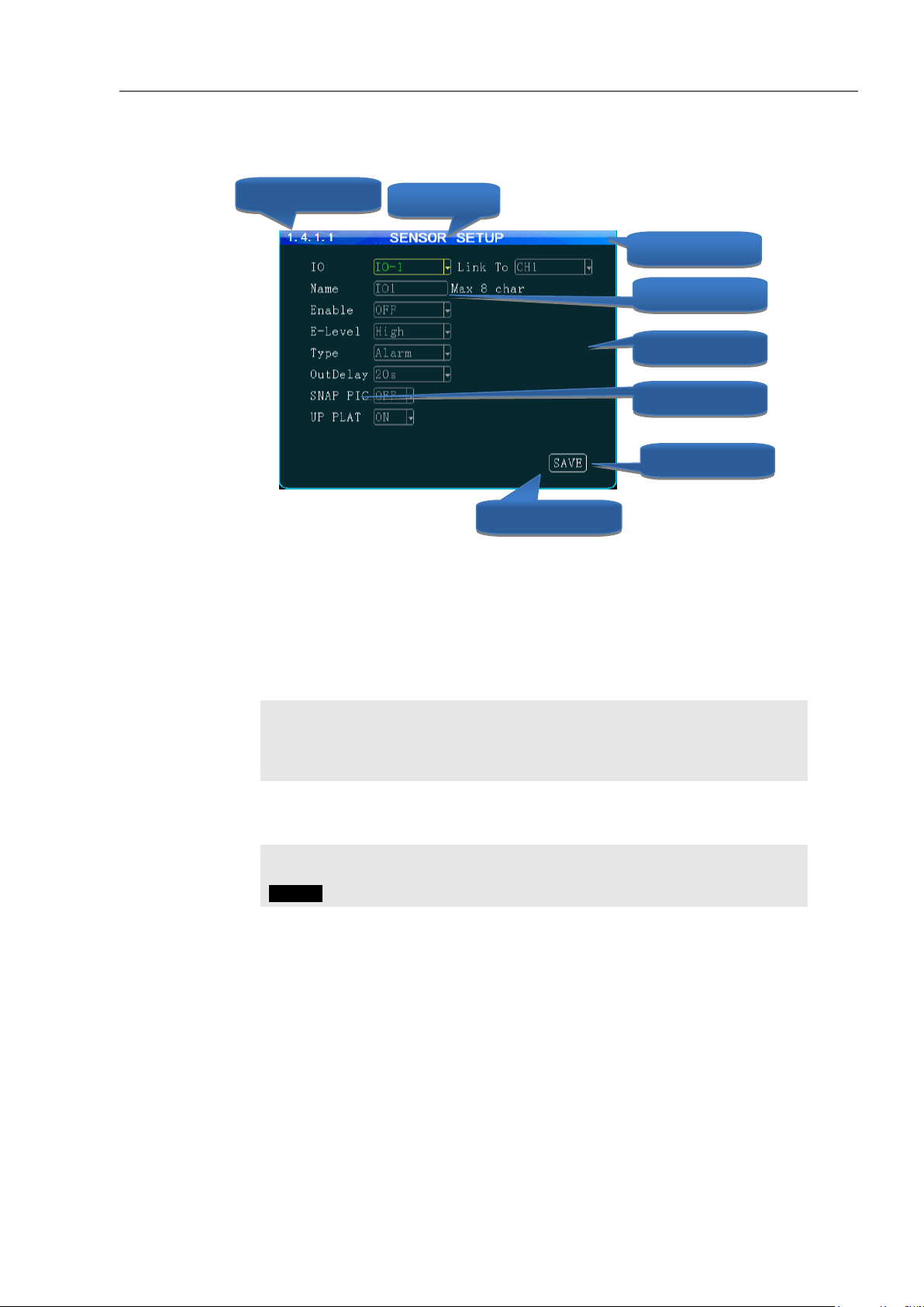
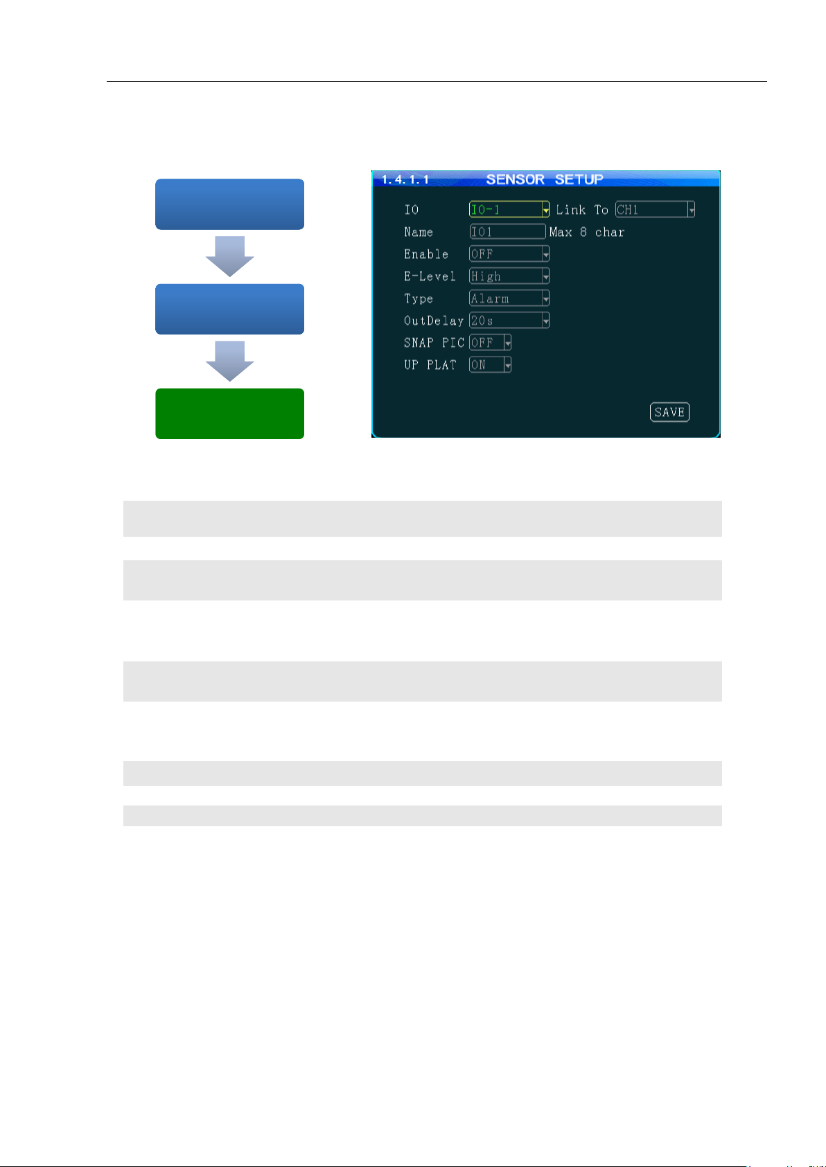
SENSOR IN
(IO)
Define the trigger response relationship for each of the 8 SENSOR IN (Input)
NAME
Name of SENSOR IN device (8 Characters)
LINK TO
Enter Camera channel (CH) to switch to full screen and display video when
assigned SENSOR IN is triggered
ENABLE
Select from two options:
ON The selected functions are ‘On’
OFF The selected functions are ‘Off’
E- LEVEL
HIGH Detect when Voltage is ‘On’
LOW Detect when Voltage is ‘Off’
TYPE
Select type of response is to be sent when the V LEVEL SETTING is matched:
ALARM Triggers a response sent to one of the two SENSOR OUT ports
SYSTEM Triggers an entry into the SYSTEM and/or ALARM/EVENT LOG
POST RECORD
Select the time delay in seconds for ending a triggered recording
SNAPSHOT
Takes a single picture
UP PLAT
Alarm information reported to the management center
SETUP MENU 1.4
'ALARMS'
SETUP MENU 1.4
'ALARMS'
ALARM SETUP 1.4.1
'SENSORS'
ALARM SETUP 1.4.1
'SENSORS'
SENSOR SETUP
1.4.1.1
SENSOR SETUP
1.4.1.1
Mobilemule™
1.4.1.1 SENSOR SETUP
The 1.4.1.1 SENSOR SETUP screen defines the trigger response relationship between each of the 8 Sensor
In (Inputs) and actions available.
Page 35

- 35 -
SOURCE
Select the source for the speed related data:
GPS Select to use to GPS data to obtain vehicle speed information.
VEHICLE Select to use speed related data from the optional VEHICLE SPEED
MODULE
COEFF(X100)
Only used when the VEHICLE SPEED OPTION is installed:
Set according to User Manual provided with the VEHICLE SPEED MODULE
UNIT
Unit of speed measurement
KMH Kilometers per Hour
MPH Miles per Hour
ENABLE
Select from two options:
ON The selected functions are ‘On’
OFF The selected functions are ‘Off’
NAME
Enter the speed (up to 3 digits) at which to trigger the response required:
LOW(L-SPD) Sends a trigger when the vehicle speed falls below the entered speed
HIGH(H-SPD) Sends a trigger when the vehicle speed exceeds the entered speed
TYPE
Select the Type of Trigger response required:
ALARM Sends a trigger to generate an alarm (See 1.4.5.1 ALARM OUT SETUP)
EVENT Sends a trigger to enter a message in the ALARM/EVENT Log
SAVE
To save and activate the new settings
SETUP MENU 1.4
'ALARMS'
SETUP MENU 1.4
'ALARMS'
ALARM SETUP 1.4.2
'SPEED'
ALARM SETUP 1.4.2
'SPEED'
SPEED SETUP
1.4.2.1
SPEED SETUP
1.4.2.1
MASTER MENU 1.4
'ALARMS'
MASTER MENU 1.4
'ALARMS'
SPEED SETUP 1.4.2
'SPEED'
SPEED SETUP 1.4.2
'SPEED'
SPEED SETUP
1.4.2.1
SPEED SETUP
1.4.2.1
Mobilemule™
1.4.2.1 SPEED SETUP
The 1.4.2.1 SPEED SETUP screen allows the User to trigger the MDVRs Recording Mode based on low
and high speed thresholds determined by the settings entered. Either or both High and Low settings may be
entered independently.
Vehicle speed can be monitored and recorded using the speed data (KPH or MPH) from either the onboard
GPS (optional) or a more accurate speedometer sensor (optional). The Speed Alert can be set to monitor
Upper and Lower Speed Limits to trigger an alarm, log, and record the event.
Action Bar Keys (Select, then press ENTER):
Page 36

- 36 -
AXIS(NAME)
(No user entry) The three AXIS of movement of the monitored vehicle are:
X = ROLL Possible high speed into turns relative to load
Y = PITCH Possible Hard braking or acceleration, speed bumps, etc.
Z = YAW Possible bad shocks, uneven road or unsecured load, etc.
DATA
(No user entry) Displays the current G Force reading for each Axis
ENABLE
Select from two options:
ON The selected functions are ‘On’
OFF The selected functions are ‘Off’
TRIGGER(THRESHOLD)
Enter the G Force setting (up to 3 digits) at which to trigger the response
required:
Sends a Trigger when the vehicle G Force is less than or greater than the
trigger setting
TYPE
Select the Type of Trigger response required:
ALARM Sends a trigger to generate an alarm (See 1.4.5.1 ALARM OUT
SETUP)
EVENT Sends a trigger to enter a message in the ALARM/EVENT Log
CALIBRATE
Select after installing the MDVR to reorient the G Sensor
SETUP MENU 1.4
'ALARM'
SETUP MENU 1.4
'ALARM'
ALARM SETUP 1.4.3
'G SENSOR'
ALARM SETUP 1.4.3
'G SENSOR'
G SENSOR SETUP
1.4.3.1
G SENSOR SETUP
1.4.3.1
MASTER MENU 1.4
'ALARMS'
MASTER MENU 1.4
'ALARMS'
ALARM SETUP 1.4.3
'G SENSOR'
ALARM SETUP 1.4.3
'G SENSOR'
G SENSOR SETUP
1.4.3.1
G SENSOR SETUP
1.4.3.1
Mobilemule™
1.4.3.1 G SENSOR SETUP
The 1.4.3.1 G SENSOR SETUP screen (accelerometer) enables the MDVR to monitor the movement of the
vehicle in 3 Axes (X, Y, Z) and can be used to trigger a response based on the Trigger values set in the G
Sensor Menu. Readings from the sensor may indicate hard braking, acceleration, impact, sharp turns, etc.
This data may be used to evaluate driver and vehicle performance, maintenance cycles and load dynamics.
Action Bar Keys (Select, then press ENTER):
Page 37

- 37 -
1.4.4.1 TEMPERATURE SETTINGS
DEVICE
Select the Sensor used as the temperature reporting source:
MDVR/DISK MDVR internal temperature (Standard)
TEMP EXT (1 – 4 ) External temperature sensors, up to 4 (Optional)
NAME
Enter a unique name for each temperature reporting source
UNIT
Select the unit of temperature measurement:
F Fahrenheit
C Celsius
RANGE
(NAME)
There are two settings (each optional) to create the upper and lower temperature range:
LOW(L-TEMP) Low temperature setting row
HIGH(H-TEMP) High temperature setting row
ENABLE
Select the operational status of this function:
ON The selected functions are ‘On’
OFF The selected functions are ‘Off’
TRIGGER(T
HRESHOLD)
Enter the Temperature limits and select + or – indicators as needed:
LOW The Low temperature to trigger a response
HIGH The high temperature to trigger a response
TYPE
Select one of two options:
ALARM Event will be, recorded, logged and searchable as an ALARM
EVENT Event will be, recorded, logged and searchable as SYSTEM
SAVE
To save and activate the new settings
SETUP MENU
1.4 'ALARM'
SETUP MENU
1.4 'ALARM'
ALARM 1.4.1
'TEMPERATURE'
ALARM 1.4.1
'TEMPERATURE'
TEMPERATURE
1.4.4.1
TEMPERATURE
1.4.4.1
Mobilemule™
The 1.4.4.1TEMPERATURE SETUP screen allows the User to trigger the MDVRs Recording Mode based
on low and high temperature thresholds determined by temperature settings entered. Either or both High and
Low settings may be entered independently.
Action Bar Keys (Select, then press ENTER):
Page 38

- 38 -
ALM SOURCE
(ASOURCE)
The input to trigger the ALM (Alarm) Output
ALM OUTPUT
(OUTPUT)
The output path to a Sensor Output
LOG
Select whether the detected Alarm is also logged as an ALARM
SENS IN
Select one of 8 Sensor Inputs (SENS IN)
TEMP IN
(DISK BTP)
Select one of 5 Temperature inputs (TEMP IN 1 is standard. All others require
optional external sensor devices.
SPEED
Monitors High and Low speed settings in 1.4.2.1 SPEED SETTINGS
G SENSOR
Monitors X, Y, Z settings in 1.4.3.1 G SENSOR SETUP
VIDEO LOSS
Monitors Video Loss (Camera malfunction)
MOTION DET
Monitors movement or light changes sensed by the 1.4.6.1 MOTION DETECTION
SETUP
HW ERROR
Monitors factory set criteria for the detection of hardware level errors
GPS ERROR
Monitors factory set criteria for the detection of GPS Module signal reception errors
SAVE
To save and activate the new settings
SETUP MENU 1.4
''ALARM'
SETUP MENU 1.4
''ALARM'
ALARM 1.4.5
'ALARM OUT'
ALARM 1.4.5
'ALARM OUT'
ALARM OUT
SETUP 1.4.5.1
ALARM OUT
SETUP 1.4.5.1
Mobilemule™
1.4.5.1 ALARM OUT SETUP
The 1.4.5.1 ALARM OUT SETUP screen defines the Input – Trigger – Response relationships with the
various sensors and reporting devices connected to the MDVR. The ALARM OUT SETUP screen adds the
ability to add ALARM and ALARM logging responses to the other criteria set within the individual Sensor
and Device screens.
Action Bar Keys (Select, then press ENTER):
Page 39

- 39 -
1.4.6.1 MOTION DETECTIONSETUP
Setup and subsequently test each camera using the
motion detection function
1.4.6.1.1 MOTION DETECTION GRID
Setup the motion detection activation zone
1.4.5.1ALARM OUT SETUP
Setup the motion detection response to trigger an
ALARM OUT and/or LOG the event.
ENABLE
Select from two options:
ON The selected functions are ‘On’
OFF The selected functions are ‘Off’
SENSITIVITY
Select from three levels:
LOW
MED
HIGH
AREA
Select the SETUP field. The 1.4.6.1.1 MOTION DETECTION screen will appear as
an overlay on the camera view. The SETUP button backgrounds are color coded to
display their status:
BLACK Motion Detection area has not been setup
GREEN Motion Detection Zone is ready to detect
YELLOW Motion Detection has been triggered
SETUP
When you select the Area ‘SETUP’ button the 1.4.6.1.1 MOTION DETECTION
GRID screen is displayed. Instruction and setup of the motion detection zone are on
the following page
SAVE
To save the Motion Detection Zone settings
ALARM OUT SETUP
To move to the 1.4.5.1 ALARM OUT SETUP screen and add a response
SETUP MENU 1.4
'ALARM'
SETUP MENU 1.4
'ALARM'
ALARM 1.4.6
'MOTION'
ALARM 1.4.6
'MOTION'
MOTION DETECTION 1.4.6.1
'ALARM OUT SETUP'
MOTION DETECTION 1.4.6.1
'ALARM OUT SETUP'
ALARM OUT SETUP 1.4.5.1 ALARM OUT SETUP 1.4.5.1
Mobilemule™
1.4.6.1 MOTION DETECTION
The 1.4.6.1 MOTION DETECTION screen is the first of three screens necessary for the setup, activation
and testing of the motion detection features for each camera channel. Motion Detection based triggering
may only be used when the vehicle is parked or when the camera is in an enclosed area of the vehicle, as
changing lighting conditions may trigger the Motion Detection Zone.
Setup must be complete for all three screens to properly enable and test the motion detection function:
Action Bar Keys (Select, then press ENTER):
Page 40

- 40 -
CLEAR
No detection set
YELLOW
Cursor position
BLUE
Detection area set
SELECT
Move Yellow Cursor to the square to be enabled as part of the Detection Zone
ENTER
Press to enable (Becomes Blue) or disable the square (Becomes Clear)
REPEAT
Continue until the Detection Zone is defined
RETURN
Press to return to the 1.4.6.1 MOTION DETECTION screen.
The affected camera button will display a Green background if it is setup to be tested.
For a motion detected response to trigger an ALARM and/or LOG the event it is
necessary to go to the 1.4.5.1 ALARM OUT SETUP screen and complete the
related setup process
SETUP MENU 1.4
'ALARM'
SETUP MENU 1.4
'ALARM'
ALARM 1.4.6
'MOTION'
ALARM 1.4.6
'MOTION'
MOTION DETECTION 1.4.6.1
'SETUP'
MOTION DETECTION 1.4.6.1
'SETUP'
MOTION DETECTION SETUP
GRID 1.4.6.1.1
MOTION DETECTION SETUP
GRID 1.4.6.1.1
CURSOR
DETECTION
NO DETECTION
Mobilemule™
1.4.6.1.1 MOTION DETECTION SETUP GRID
The 1.4.6.1.1 MOTION DETECTION GRID is the second of three screens required to setup and test the
Motion Detection function. It allows the user to define a detection zone to automatically trigger the functions
set in the 1.4.6.1 MOTION DETECTION SETUP and the 1.4.5.1 ALARM OUT SETUP screen.
Motion Detection Zone (MDZ) definition:
A User defined grid of transparent squares overlaid on a Camera view creating a response to light or
movement. The User can define the active motion detection zone with Blue squares.
Once all three related screens are properly setup, a detected movement meeting the parameters set will
trigger a response governed by the 1.4.5.1 ALARM OUT screen.
Create the Active Motion Detection Zone:
To setup additional cameras repeat the above and continue setting up the parameters for each camera as
necessary.
Page 41

- 41 -
ACC TIMEOUT
(TIMEOUT PARK)
Select the length of time before and alarm is sent and logged. Monitors the time
the Vehicle Ignition Switch is in the ACC position and reports it to the IVMS
REST REMINDER
(FATIGUE DRIVE)
Select the length of time before and alarm is sent and logged. Monitors the time
the Vehicle Ignition Switch is in the ON position and reports it to the IVMS
SAVE
To save and activate the new settings
SETUP MENU 1.4
'ALARM'
SETUP MENU 1.4
'ALARM'
ALARM SETUP 1.4.7
'OTHER ALARMS'
ALARM SETUP 1.4.7
'OTHER ALARMS'
OTHER ALARMS
1.4.7.1
OTHER ALARMS
1.4.7.1
Mobilemule™
1.4.7.1 OTHER ALARMS
The 1.4.7.1 OTHER ALARMS screen allows the IVMS to monitor Driver (Vehicle) activity by monitoring
the time elapsed alarms for each field.
Action Bar Keys (Select, then press ENTER):
Page 42

- 42 -
EXPORT CONFIG FILE
Select to copy this MDVRs system settings to an USB flash drives for
use as backup or to easily setup another MDVR:
1. Insert the USB flash drives on the front panel
2. Select EXPORT CONFIG FILE button
3. Remove USB flash drives
IMPORT CONFIG FILE
Use to copy the above MDVRs system settings to the one to be
programmed.
1. Ensure MDVR is powered Off and in UNLOCK position
2. Insert USB flash drives containing the EXPORT CONFIG FILE
3. Close the Security Door and turn Key to the 'LOCK’ position
4. MDVR will start up and automatically copy the settings on the USB
flash drives and complete the startup process
5. When the Camera Screen appears Turn Key to ‘UNLOCK’ position
6. Open Security Door; remove the USB flash drives
RESET TO DEFAULT
(DEFAULT CONFIG)
Resets MDVR to the original factory settings and permanently deletes any
other settings. The SYSTEM will prompt you to reconfirm prior to
completing the reset to original settings
CHANGE LOGO
(UPGRADE LOGO)
Add or upgrade a logo to be displayed on the MDVRs LCD Monitor during
the start up process
SETUP MENU 1.5
'TOOLS'
SETUP MENU 1.5
'TOOLS'
TOOLS 1.5.1
'CONFIGURE'
TOOLS 1.5.1
'CONFIGURE'
CONFIGURE 1.5.1.1
'CONFIGURATION'
CONFIGURE 1.5.1.1
'CONFIGURATION'
Mobilemule™
1.5.1.1 CONFIGURATION
The 1.5.1.1CONFIGURATION screen allows the user to copy the basic system settings from one MDVR and
transfer (Export) them to another MDVR using an USB flash drives.
Page 43

- 43 -
DISK
PARTITION
Select from two options to be formatted and press ENTER
SIGNLE One partition after formatting the disk
MULTIPLE Multiple partitions after formatting the disk
SELECT
Select from two options to be formatted and press ENTER:
HDD Hard Disk Drive (Regular HDD will be formatted as EXT3)
SD SD Card
FORMAT
Select and press ENTER to begin Format process
READ
SYSTEM
WARNING
1.5.2.1 SYSTEM WARNING screen will appear:
OK
To FORMAT: Select and press ENTER. No other warnings will appear
CANCEL
To CANCEL: Select and press ENTERto return to the beginning of the Format process
FORMAT
To begin Format process
OK
To FORMAT. No other warnings will appear
CANCEL
To CANCEL
SETUP MENU 1.5
'TOOLS'
SETUP MENU 1.5
'TOOLS'
TOOLS 1.5.2
'FORMAT'
TOOLS 1.5.2
'FORMAT'
FORMAT 1.5.2.1 FORMAT 1.5.2.1
Mobilemule™
1.5.2.1 FORMAT STORAGE MEDIA
The 1.5.2.1 FORMAT screen allows the User to format Storage Media a (HDD, SSD or SD Card) prior to its
initial use or to reformat (erase) a previously used (recorded on) for reuse. Use only name brand SD Cards rated
Class 10 or better.Use only an SV rated, EXT3 formatted HDD/SSD in the Drive Tray.
To Format :
Action Bar Keys (Select, then press ENTER):
Page 44
- 44 -
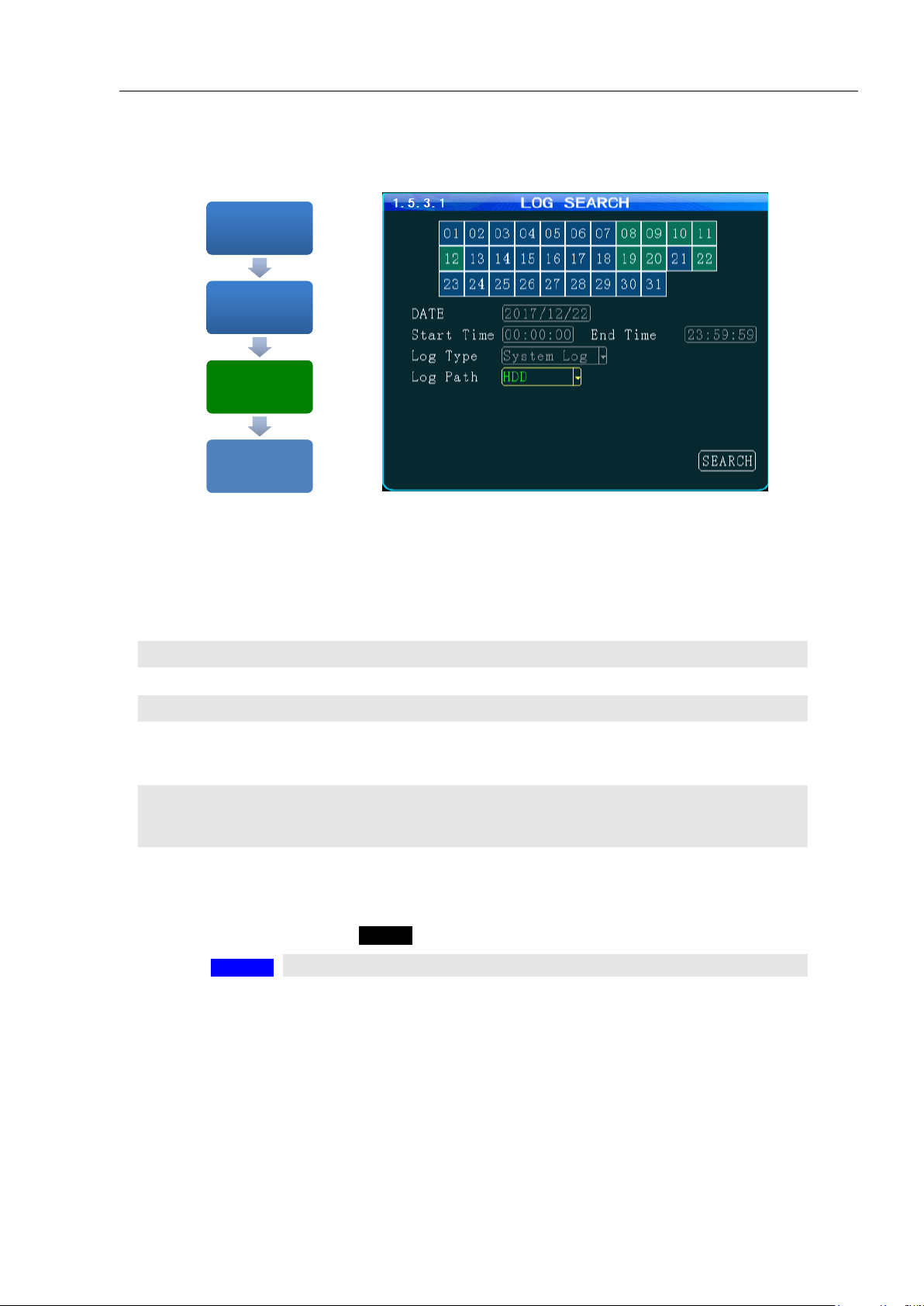
SEARCH DATE
Enter the date to be searched in the format shown in this field
START TIME
Enter the Start Time in 24 hour format for the files to be searched
END TIME
Enter the End Time in 24 hour format for the files to be searched
TYPE
Select from three options:
SYSTEM Search recorded operating system events, i.e., On, Off, Changes, etc.
ALARM Search recorded ALARMS, i.e., Sens Out, etc.
PATH
PATH Select the file storage source on the MDVR:
HDD Search recorded files on the Hard Disk Drive
SD Search recorded files on the SD Card
SEARCH
To the 1.5.3.1.1 SEARCH LOG LIST
SETUP MENU 1.5
'TOOLS'
SETUP MENU 1.5
'TOOLS'
TOOLS 1.5.3
'LOG'
TOOLS 1.5.3
'LOG'
SEARCH ALARM and
SYSTEM LOGS 1.5.3.1
'SEARCH'
SEARCH ALARM and
SYSTEM LOGS 1.5.3.1
'SEARCH'
SEARCH LOG LIST
1.5.3.1.1
SEARCH LOG LIST
1.5.3.1.1
Mobilemule™
1.5.3.1 SEARCH SYSTEM and ALARM LOGS
The SEARCH SYSTEM and ALARM LOGS Menu allows the user to search all logged events or to search
for specific predetermined events the MDVR previously recorded on the installed HDD or SD Card.
The colored grid shown lists the days of the search month. To expedite file searches Days with recordings
available have a green background.
Action Bar Keys (Select, then press ENTER):
ENTER
Page 45

- 45 -
1.5.3.1.1 SEARCH LOG LIST
DATE
(YY/MM/DD) Specific Date the listed event occurred
TIME
(24 Hour Format) Specific start time of the recorded file found
TYPE
Shows Type of Log file recorded to:
SYSTEM
ALARM
DETAIL
Provides description of logged event
FIRST
Move cursor to first page in search results
LAST
Move cursor to last page in search results
NEXT
Move cursor to next (lower) page in search results
PREV
Move cursor to previous page in search results
EXPORT
Export LOG LIST
RETURN
Press to return to the 1.5.3.1 SEARCH SYSTEM and ALARM LOGS screen
SETUP MENU 1.5
'TOOLS'
SETUP MENU 1.5
'TOOLS'
TOOLS 1.5.3
'LOGS'
TOOLS 1.5.3
'LOGS'
SEARCH SYSTEM
and ALARM LOGS
1.5.3.1 'SEARCH'
SEARCH SYSTEM
and ALARM LOGS
1.5.3.1 'SEARCH'
SEARCH LOG LIST
1.5.3.1.1
SEARCH LOG LIST
1.5.3.1.1
The 1.5.3.1.1 SEARCH LOG LIST allows the user to view the results of the search criteria entered on the
1.5.3.1 SEARCH SYSTEM and ALARM LOGS screen. Use the Action Bar keys to navigate the list.
Mobilemule™
Action Bar Keys (Select, then press ENTER):
Page 46

4 Channels HDD MDVR (720P) USER GUIDE V6.0 (DRAFT)
- 46 -
DEVICE
(CH-X)
Select one of four channels for the PTZ Camera to use:
PTZ 1-4
PROTOCOL
Select from two industry standard PTZ operating codes:
PELCO D
PELCO P
BAUDRATE
Select to match the settings on the PTZ Camera
DATA BIT
Select to match the settings on the PTZ Camera
STOP BIT
Select to match the settings on the PTZ Camera
CHECK
Select to match the settings on the PTZ Camera
ADDR
Enter to match the settings on the PTZ Camera. Each PTZ Camera must have a
different address
SAVE
To save and activate the new settings
SETUP MENU 1.6
'PERIPHERALS'
SETUP MENU 1.6
'PERIPHERALS'
PERIPHERALS
SETUP 1.6.1
'PTZ SETUP'
PERIPHERALS
SETUP 1.6.1
'PTZ SETUP'
PTZ SETUP
1.6.1.1
PTZ SETUP
1.6.1.1
1.6.1.1 PTZ CAMERA SETUP
The 1.6.1.1 PTZ CAMERA SETUP screen allows up to four PTZ (Pan, Tilt, Zoom) Cameras to be
programmed, viewed and controlled by the MDVR using its IR Remote Control (IRC) or a compatible PTZ
Joystick Control Console.
Read the manual supplied by the PTZ Cameras manufacturer.
Set the operational codes on the camera as required. Then enter the same codes in the MDVR using the PTZ
Camera screen. Ex.: Pelco D (Protocol), 2400 (Baud), 1 (Data Bit), 1 (Stop Bit), NONE (Check).
The ADDR can be from 1 – 255 and must be unique for each device.
Action Bar Keys (Select, then press ENTER):
Page 47

4 Channels HDD MDVR (720P) USER GUIDE V6.0 (DRAFT)
- 47 -
CELLULAR(WIRELESS)
Select from two options:
ON Cellular features and functions are On
OFF Cellular features and functions are Off
APN
Enter APN Provided by Cellular Service Provider
CENTER NUM
(*99#) Default entry
USER NAME
(Up to 16 characters) Optional User entry
PASSWORD
(Up to 16 characters) Optional User entry
SAVE
To save and activate the new settings
SETUP MENU 1.6
'PERIPHERALS'
SETUP MENU 1.6
'PERIPHERALS'
PERIPHERALS 1.6.2
'WIRELESS SETUP'
PERIPHERALS 1.6.2
'WIRELESS SETUP'
WIRELESS SETUP
1.6.2.1
WIRELESS SETUP
1.6.2.1
1.6.2.1 WIRELESS SETUP
The 1.6.2.1WIRELESS SETUP screen allows the setup of the (optional) Cellular communications
capability of the MDVR allowing real time cellular communication between the MDVR and the IVMS using
a carrier compatible SIM Card (Second Card option available) and the Cellular Communication Option
installed.
SIM Card Setup
A SIM Card compatible with the MDVRs internal cellular modem (Optional) must be inserted in the SIM
slot located on the front of the MDVR. See SIM CARD INSTALLATION in the HARDWARE SETUP
SECTION OF THE user Guide for the correct procedure.
Antenna
A compatible Cellular Antenna must be connected properly to the MDVR and correctly installed on the
vehicle. See WIRELESS ANTENNA INSTALLATION in the HARDWARE SETUP SECTION OF THE
user Guide for the correct procedure.
Confirm the new settings are correct and save the file.
Action Bar Keys (Select, then press ENTER):
Page 48

4 Channels HDD MDVR (720P) USER GUIDE V6.0 (DRAFT)
- 48 -
WIFI MODE
Select from two options:
INTERNAL WIFI MODEM Option is installed inside the MDVR
EXTERNAL WIFI MODEM Option is installed outside the MDVR
MULTIHOT
SPOT
To Connect multiple WIFI hotspots
ON
OFF
ENABLE
Select from two choices:
ON Activate the installed WIFI function
OFF No WIFI option is installed or the installed option is off
LINK TO
(WIFI
HOTSPOT)
To establish connection between the MDVR and the IVMS Server, please input
IVMS central IP and port number
SSID
(Standard Format)
IP ADDR.
(Standard Format)
NETMASK
(Standard Format)
GATEWAY
(Standard Format)
ENCRYPT
Select from two options:
ON Encryption mode is active
OFF Encryption function is off
GET IP MODE
Select from two options:
STATIC
DYNAMIC
AUTH MODE
Select from five options:
1. OPEN 2. SHARED 3. WPA 4. WPA-PSK 5. WPA2-PSK
Select OPEN as initial setting.
TYPE
Select from two options:
NONE
WEP
PASSWORD
(Up to16 Characters) Enter a password (optional)
SETUP MENU 1.6
'PERIPHERALS'
SETUP MENU 1.6
'PERIPHERALS'
PERIPHERALS 1.6.3
'WIFI SETUP'
PERIPHERALS 1.6.3
'WIFI SETUP'
WIFI SETUP 1.6.3.1
WIFI SETUP 1.6.3.1
1.6.3.1 WIFI SETUP (Optional module required)
The WIFI SETUP Menu allows the setup of the optional WIFI communications capability of the MDVR
allowing real time WIFI communication between the MDVR and the IVMS using either an (optional)
internal or external WIFI (802.11n or AC) Modem. Note: Use IRC number keys to enter (Standard Format)
address data used in your current wireless LAN network settings. CONTACT YOUR IT PERSON FOR
SUPPORT.
Page 49

4 Channels HDD MDVR (720P) USER GUIDE V6.0 (DRAFT)
- 49 -
DEVICE(ID)
Select the Sensor used as the reporting source:
TANK (1 – 4)
COEFF
(Optional) The Coefficient is an element of calculation adjustment varying with
different brands and types of fuel or liquid storage measurement devices. Consult
the Device manufacturer for details
TRIGGER
Enter the minimum amount of fuel (or other fluid) level measurement units to
trigger a response
ENABLE
Select the operational status of this function:
ON The selected functions are ‘On’
OFF The selected function are ‘Off’
ADDR
Enter to match the settings on the FUEL SETUP.
SAVE
To save and activate the new settings
SETUP MENU 1.6
'PERIPHERALS'
SETUP MENU 1.6
'PERIPHERALS'
PERIPHERALS 1.6.4
'FUEL'
PERIPHERALS 1.6.4
'FUEL'
FUEL SETUP 1.6.4.1 FUEL SETUP 1.6.4.1
1.6.4.1 FUEL SETUP
The 1.6.4.1 FUEL SETUP Menu allows the user to track and record fuel (or other transported fluids) usage
or delivery. The use of this feature requires an optional Fuel Sensor connecting via RS 232 or RS 485.
Action Bar Keys (Select, then press ENTER):
Page 50

4 Channels HDD MDVR (720P) USER GUIDE V6.0 (DRAFT)
- 50 -
DEVICE
Select each of two control channels to setup connected devices:
COM 1
COM 2
NAME
Enter a unique name for the RS 232 device (Up to10 characters)
BAUD
Select to match the settings on the RS 232 device
DATA BIT
Select to match the settings on the RS 232 device
STOP BIT
Select to match the settings on the RS 232 device
CHECK
Select to match the settings on the RS 232 device
ENABLE
Select from two options:
ON The selected functions are ‘On’
OFF The selected functions are ‘Off’
MCU COM1
Enter a unique name for the RS 485 device (Up to10 characters)
NAME
Select to match the settings on the RS 485 device
SAVE
To save and activate the new settings
SETUP MENU 1.6
'PERIPHERALS'
SETUP MENU 1.6
'PERIPHERALS'
PERIPHERALS 1.6.5
'SERIAL''
PERIPHERALS 1.6.5
'SERIAL''
SERIAL DEVICE
SETUP 1.6.5.1
SERIAL DEVICE
SETUP 1.6.5.1
1.6.5.1 SERIAL DEVICE SETUP
The 1.6.5.1 SERIAL DEVICE SETUP screen allows up to two RS 232 data or control devices to be setup
using industry standard RS 232 code settings.
The 1.6.5.1 SERIAL DEVICE SETUP screen allows up to eight compatible RS 485 data or control devices
to be setup using industry standard RS 485 code settings.
NOTE: This does not include the PTZ Cameras setup in the 1.6.1.1 PTZ CAMERA SETUP.
Action Bar Keys (Select, then press ENTER):
Page 51

4 Channels HDD MDVR (720P) USER GUIDE V6.0 (DRAFT)
- 51 -
SEARCH DATE
Enter the Date to be searched in the format shown in this field
START TIME
Enter the Start Time in 24 hour format for the files to be searched
END TIME
Enter the End Time in 24 hour format for the files to be searched
PATH
Select the file storage source:
HDD Hard Disk Drive
SD 2 SD Card
TYPE
Select the Type of recordings to search for the time period entered:
ALL Search ALL recordings
GENERAL Search only GENERAL labeled recordings
ALARM Search ALARM labeled recording
CHANNEL
Select the Video Channel (CH 1 – 4) to be displayed for the time period entered:
ALL Search ALL camera channels for recordings
CH 1 – 5 Search a specific Camera channel (CH) for recordings. Channel 5 may
not be available depending on 1.2.1 CAMERA MIX screen settings
SEARCH
To search and move to the 1.7.1.1 SEARCH PLAYBACK LIST
SETUP MENU 1.7
'SEARCH'
SETUP MENU 1.7
'SEARCH'
SEARCH 1.7
'SEARCH RECORDINGS'
SEARCH 1.7
'SEARCH RECORDINGS'
SEARCH RECORDINGS 1.7.1
'SEARCH'
SEARCH RECORDINGS 1.7.1
'SEARCH'
SEARCH PLAYBACK LIST
1.7.1.1
SEARCH PLAYBACK LIST
1.7.1.1
1.7.1 SEARCH RECORDINGS
The 1.7.1 SEARCH RECORDINGS screen allows the user to search by Date, Path (Storage Media) and Type
(ALL, GENERAL or ALARM) list all recorded events or to search for specific predetermined events the
MDVR previously recorded on the installed storage media Path.
The colored grid shown lists the days of the search month. To expedite file searches Days with recordings
available have a green background.
Action Bar Keys (Select, then press ENTER):
Page 52

4 Channels HDD MDVR (720P) USER GUIDE V6.0 (DRAFT)
- 52 -
DATE
Search date for recorded files listed (No User entry)
CH
Camera channel recorded from (No User entry)
TYPE
Search Type producing listing:
ALL, GENERAL or ALARM
START
Start time for the recording (No User entry)
END
End time for the recording (No User entry)
RES
Video Resolution of the recording (No User entry)
SIZE
Size of the recorded file (No User entry)
CHECK BOX
Select file and press
ENTER
to mark the file for viewing
FIRST
Move cursor to first PAGE
LAST
Move cursor to last PAGE
PREV
Move cursor to previous PAGE
NEXT
Move cursor to next PAGE
SELECT ALL
Select all files. Fills in all check boxes
INVERSE
Reverse file listing order
EXPORT
To save the selected files to a USB Drive inserted into the front panel USB
report. A 1.7.1.1.A SYSTEM MESSAGE will appear and display the File
Transfer status until the download is completed
RETURN
Press to return to the 1.7.1.1 SEARCH PLAYBACK LIST screen
SETUP MENU 1.7
'SEARCH'
SETUP MENU 1.7
'SEARCH'
SEARCH 1.7
'SEARCH RECORDINGS'
SEARCH 1.7
'SEARCH RECORDINGS'
SEARCH RECORDINGS
1.7.1 'SEARCH'
SEARCH RECORDINGS
1.7.1 'SEARCH'
SEARCH PLAYBACK LIST
1.7.1.1 'ENTER'
SEARCH PLAYBACK LIST
1.7.1.1 'ENTER'
1.7.1.1 SEARCH PLAYBACK LIST
The 1.7.1.1 SEARCH PLAYBACK LIST displays the results of the last 1.7.1 SEARCH RECORDINGS
screen. Select the file or files. To Playback the recorded file(s) selected above use the instructions on the
following page.
Action Bar Keys (Select, then press ENTER):
To playback the selected file(s) follow the instructions on the next page.
Page 53

4 Channels HDD MDVR (720P) USER GUIDE V6.0 (DRAFT)
- 53 -
VIEW FILE
Once the file is completely played the 1.7.1.1 SEARCH PLAYBACK LIST screen
will be displayed and the last viewed selection highlighted.
RETURN
Press to end viewing and return to the 1.7.1.1 SEARCH PLAYBACK LIST screen
PLAY
Starts Playback of the selected recorded file. Press repeatedly to increase
Playback speed by X2, X4, X8, X16
REW
REWIND Reverses the Playback of the selected recorded file. Press repeatedly
to increase Reverse speed by X2, X4, X8, X16
FWD
FAST FORWARD
PAUSE/STEP
Press to pause recording. Press to advance one frame per press
1.7.1.1 VIEWING FILES
Two options to return to the 1.7.1.1 SEARCH PLAYBACK LIST screen
IRC Playback Related Keys:
Page 54

4 Channels HDD MDVR (720P) USER GUIDE V6.0 (DRAFT)
- 54 -
INFO
Press to view PG 1 of the System Info screens.
NEXT
Select and press ENTER to view 1.8.2 SYSTEM INFO PG 2
RETURN
Press to return to the previous page
SW
Software Version
HW
Hardware Version
SERIAL-NUM
Serial Number
MCU VER
Micro Control Unit
IMEI
The ID of the MDVR Cellular Modem Option when installed and enabled within
the MDVR for communication with the IVMS Server. It is automatically displayed
if an active SIM Card is installed.
DISK TEMP
Internal Temperature reading of DISK
SPEED
Vehicle Speed (should read ‘0’ if the vehicle is properly parked)
GPS-M
Invalid/valid?
PLUS NUM
Pulse number
3G/4G-M
Cellular Option installed?
SIM CARD
SIM Card installed(NONE/EXIST)?
WIFI-M
WIFI mode(NONE/EXIST)?
CENTER-L
Central Monitoring Station Linked?
INTERCOM-L
Intercom Station Linked?
COM 1
DEVICE
Serial Port 1 (Device Connected)
GPS-SIGN
Current GPS Longitude/ Latitude reading
INTERCOM-ID
Intercom device ID number?
3G-STATE
Cellular Status
SIM-SIGN
SIM Signal reading
WIFI-SIGN
WIFI Signal reading
SENSOR IN
STATUS
Status of 8 SENS IN channels. ALARM status is indicated by white letters on red
background
SETUP MENU 1.8
'SYSTEM INFO'
SETUP MENU 1.8
'SYSTEM INFO'
SYSTEM INFO
1.8.1
SYSTEM INFO
1.8.1
SYSTEM INFO PG
2 'NEXT'
SYSTEM INFO PG
2 'NEXT'
1.8.1 SYSTEM INFO, PG 1 OF 2
The 1.8.1 SYSTEM INFO screen is one of two sequential screens to display the current MDVR system
settings, real time operational status and optional business contact information. A compatible monitor must
be properly connected and configured to either of the MDVR Rear or Front Monitor ports.
Note: For Status Report purposes only. No User entry
Page 55
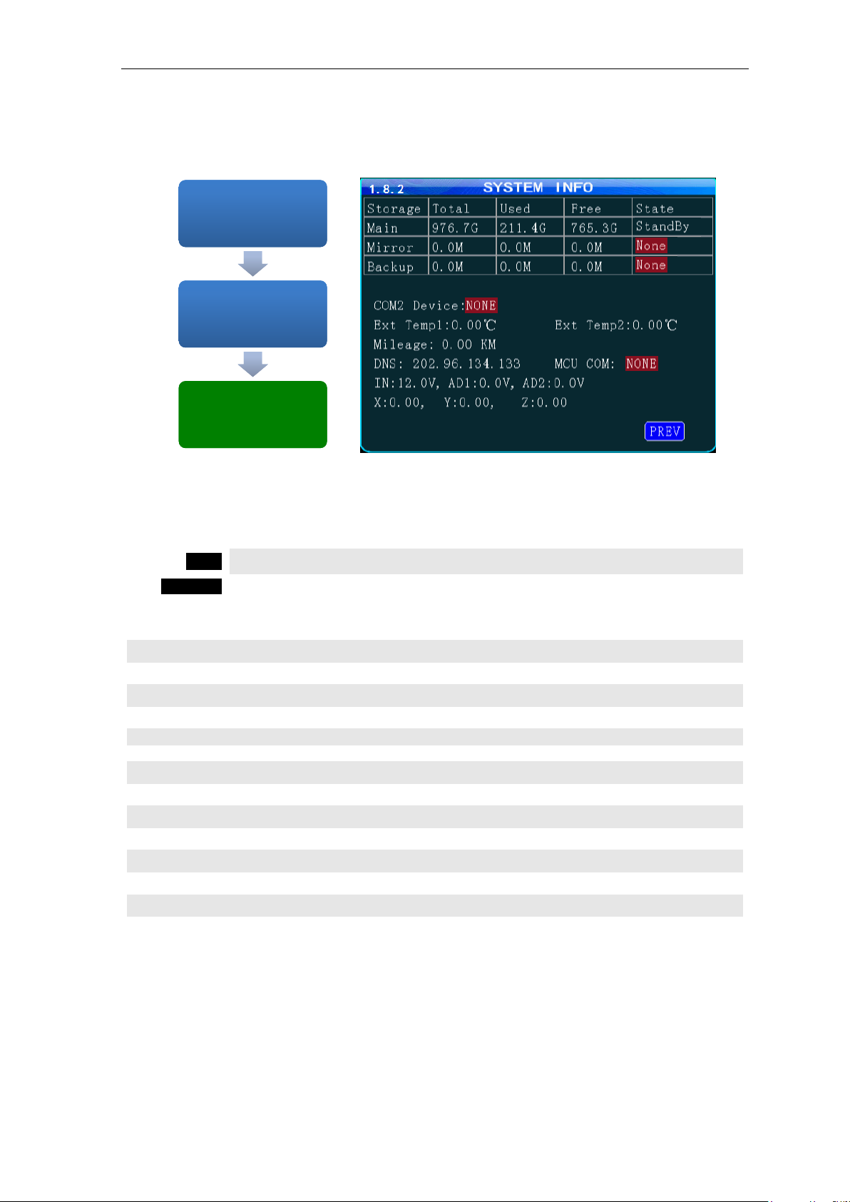
4 Channels HDD MDVR (720P) USER GUIDE V6.0 (DRAFT)
- 55 -
INFO
Press to view PG 1 of the System Info screens.
RETURN
Press to return to the previous page
MEDIA
Storage status for each of the installed recording media
COM 2 DEV
Serial Port 1 (Device Connected)
EXT TEMP 1
External Temperature Sensor 1 reading (requires optional sensor)
2
External Temperature Sensor 2 reading (requires optional sensor)
MILEAGE
Approximate distance Vehicle has traveled since last odometer setting
DNS
Domain IP of 3G/4G
MCU COM
Serial Port 1 (Device Connected)
VOLTAGE IN
Voltage supplied by vehicle to MDVR
AD 1
Sensor Out (SENS OUT 1) status
AD 2
Sensor Out (SENS OUT 2) status
G SENSOR X
Accelerometer X Axis reading
Y
Accelerometer Y Axis reading
Z
Accelerometer Z Axis reading
SETUP MENU 1.8
'SYSTEM INFO'
SETUP MENU 1.8
'SYSTEM INFO'
SYSTEM INFO PG
1 'NEXT'
SYSTEM INFO PG
1 'NEXT'
SYSTEM INFO
PG 2 'NEXT'
SYSTEM INFO
PG 2 'NEXT'
1.8.2 SYSTEM INFO, PG 2
The1.8.2 SYSTEM INFO screen shown above is Page 1 of 2 sequential screens displaying the current
MDVR system settings, operational status and business contact information.
To view the INFO screen:
Note: For Status Report purposes only. No User entries.
USER NOTES AND FEEDBACK
 Loading...