

Page 1
Instruction Manual
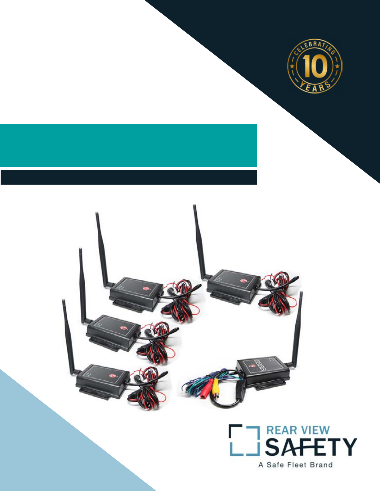
2.4G Digital Wireless Four Channel
Transmitter System
RVS-554W
Reverse With Condence ™
1
Page 2
Introduction.............................. 03
NOTE!
Please read all of the installation instructions
carefully before installing the product. Improper
installation will void manufacturer’s warranty.
Congratulations on purchasing a Rear View Safety 2.4G Digital
Wireless Four Channel Transmitter System!
With this manual you will be able to properly install and operate the
TABLE OF CONTENTS
Safety Information.............................. 04-06
Before Beginning Installation & Warning . . . . . . . . . . . . . . . . . . 07-08
System Introduction, Wiring, Pairing Process . . . . . . . . . . . . . . . . . 08
Transmitter Diagram ...................... . . . . . 09
To Alternate Between Channels ........................ . 10
System Contents and Trigger Cable Connections. . . . . . . . . . . . 11
System Specications . . . . . . . . . . . . . . . . . . . . . . . . . . . . . 12
Transmitter / Receiver Specications . . . . . . . . . . . . . . . . . . . . 13
Warranty.......................... . . . . . 14
Disclaimer.......................... . . . . . 15
unit.
The Wireless Four Channel Transmitter System is intended to be
INTRODUCTION
installed as a supplement aid to your standard rear view mirror that
already exists in your vehicle. This Wireless Backup Camera System
should not be used as a substitute for the standard rear view mirror
or for any other mirror that exists in your vehicle.
In some jurisdictions, it is unlawful for a person to drive a motor
vehicle equipped with a TV viewer or screen located forward of the
back of the driver’s seat or in any location that is visible, directly or
indirectly, to the driver while operating the vehicle.
2 3
Rear View Safety Reverse With Condence ™
Page 3

Please read the entire manual and follow the instructions and
warnings carefully. Failure to do so can cause serious damage and/or
injury, including loss of life. Be sure to obey all applicable local
trac and motor vehicle regulations as it pertains to this product.
• Electric shock or product
malfunction may occur if this
product is installed incorrectly.
INSTALLATION:
• While installing the Rear View
System be careful with the wire
positioning in order to avoid wire
Improper installation will void manufacturer’s warranty.
USAGE:
• The Rear View Safety 2.4G Digital
Wireless Four Channel Transmitter
System is designed to help the driver safely detect people and/or objects helping to avoid damage or injury. However, you the driver, must
use it properly. Use of this system is
not a substitute for safe, proper or
Transmitter System. If you back up
while looking only at the monitor,
you may cause damage or injury.
Always back up slowly.
• The Rear View Safety 2.4G Digital
Wireless Four Channel Transmitter System is not intended for use
• Use this product within the
voltage range specied. Failure to
do so can cause electronic shock or
product malfunction.
• Take special care when clean-
ing and handling components of
this system.
• Make sure to rmly ax the prod-
damage.
• The System should only be used
when the vehicle is in reverse.
• Do not watch movies or operate
the monitor while driving; as it may
cause an accident.
• Do not install the monitor compo-
nent where it may obstruct drivers
SAFETY INFORMATION
legal driving.
• Never back up while looking at the
monitor alone. You should always
SAFETY INFORMATION
check behind and around the vehicle when backing up, in the same
way as you would if the vehicle
did not have the Rear View Safety
2.4G Digital Wireless Four Channel
during extensive back-up maneuvers or backing into cross trac or
pedestrian walkways.
•Please, always remember, the area
displayed by the system is limited.
It does not display the entire panorama that is behind you.
uct before use.
• If smoke or a burning smell
is detected, disconnect the
system immediately.
• Where the power cable may touch
a metal case, cover the cable with
friction tape. A short circuit or
disconnected wire may cause a re.
view or obstruct an air bag device.
• Dropping the components of this
system may cause possible mechanical failure.
4 5
Rear View Safety Reverse With Condence ™
Page 4

If you have questions about this product, contact:
Rear View Safety
1797 Atlantic Avenue
Brooklyn, NY 11233
Tel: 1.800.764.1028
IN NO EVENT SHALL SELLER OR MANUFACTURER BE
LIABLE FOR ANY DIRECT OR CONSEQUENTIAL DAMAGES OF
ANY NATURE, OR LOSSES OR EXPENSES RESULTING FROM
Before drilling please check that no cable or wiring is on the other
side of the wall. Please clamp all wires securely to reduce the possibility of them being damaged while vehicle is in use. Keep all cables
away from hot/moving parts and electrical noisy components.
We recommend doing a benchmark test before installation
to insure that all components are working properly.
Step 1: Choose the monitor and camera locations.
Step 2: Install all cables in vehicle, when necessary a 0.8 (20mm)
BEFORE YOU BEGIN
SAFETY INFORMATION
hole should be drilled for passing camera cable through vehicles
ANY DEFECTIVE PRODUCT OR THE USE OF ANY PRODUCT.
walls. Install split grommets where applicable.
Step 3: Once all cables and wiring have been properly routed, perform a system function test by temporarily connecting the system.
Warning!
1. Monitor, cameras, and this transmitter system are high voltage. Only
professionals should open electronics. 2. Do not watch the video while
driving unless you are monitoring the rear view camera display.
6 7
Rear View Safety Reverse With Condence ™
Page 5

System Introduction
Transmitter Diagram
Wiring
Monitor or Camera(s) connect to Transmitter or Reciever through the
5-Pin Connector and recieve power from Ground Connector.
LED Indicator Lights
When connected to a power source the system
POWER and LINK will turn on. If both POWER
and LINK LED lights turn on, pairing will likely
be automatic.
LED INDICATORS
Pair Process (if pairing is not automatic)
1. Turn on POWER to monitor (if required)
)))) ((((
Monitor (Sold Separately)
Ground Connector - Power Source for
Transmitters / Reciever
5-Pin Connector - To connect Transmitter
WIRELESS SIGNAL
Reciever
2. Press and hold down PAIR red button on
Transmitter(s) and Reciever.
3. Green Link LED Light will start blinking
4. A countodwn will start counting down to "0"
(Process takes less than a minute)
5. A "pairing failed" screen may show briey
BEFORE YOU BEGIN
right before a successful pairing - disregard.
6. If system does not pair, please check wiring. Also check that LED
indicators conrm units are receiving power connection.
PAIR BUTTON
/ Reciever to Monitor or Camera(s)
Backup Camera
(Sold Seperately)
Transmitter
Transmitter
Note: A "Pairing Failed" screen may display after performing a
60 second pairing synronization. Disregard this message.
8 9
Rear View Safety Reverse With Condence ™
Backup Camera
(Sold Seperately)
Transmitter
Transmitter
Page 6

To Alternate between Channels
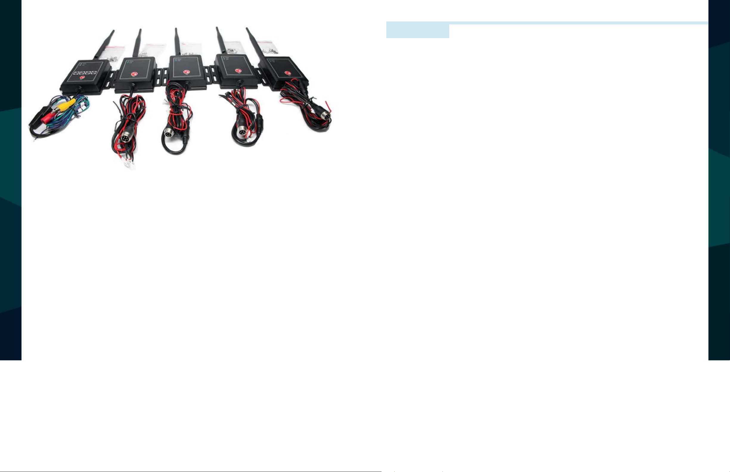
System Contents and Trigger Cable Connections
1. To alternate between
channels press buttons on
Reciever Box (CH1, CH2,
CH3, CH4).
2. Alternate between single view of all four channels.
Wireless Transmitter System Contents
1 - Reciever with Antenna
4 - Transmitter with Antennas
5 - Screw Kits
Cable Connections
CAMERA DIMENSIONS
MENU INTRODUCTION
1. DC12-24V - Ground Connection
2. Yellow RCA - Audio Connection
3. Trigger #V1 - (Green)
4. Trigger #V2 - (Blue)
5. Trigger #V3 - (Purple)
6. Trigger #V4 - (Grey)
10 11
Rear View Safety Reverse With Condence ™
Page 7

System Specications
Transmitter / Receiver Specications
Frequency 2400- 2483 MHZ
Modulation System FSK (Frequency-Shift Keying)
Operating Temperature -30°C ~ +80°C
Power Consumption Less than 2.5 W
Waterproof Rating IP69
Video Input 4 Channel (4 Wireless)
Transmission Distance 70 ft
Video Source 1Vp-p, 75
Auto Pair Yes
Power Supply 11 - 32 V
Video Input 1.0 VP-P75
Pixel Resolution 720 x 576
Frame Rate 25 - 30 Frames
Dimensions 3.75" (H) x 4" (L) x 5" (D)
Pixel Resolution 720 x 576
Transmitter Weight 2.66 KG
Reciever Weight 2.54 KG
CAMERA SPECIFICATIONS
MONITOR SPECIFICATIONS
12 13
Rear View Safety Reverse With Condence ™
Page 8

ONE YEAR WARRANTY
DISCLAIMER
REAR VIEW SAFETY, INC. WARRANTS THIS PRODUCT AGAINST MATERIAL DEFECTS FOR A
PERIOD OF ONE YEAR FROM DATE OF PURCHASE. WE RESERVE THE RIGHT TO REPAIR OR
REPLACE ANY SUCH DEFECTIVE UNIT AT OUR SOLE DISCRETION. REAR VIEW SAFETY, INC.
IS NOT RESPONSIBLE FOR A DEFECT IN THE SYSTEM AS A RESULT OF MISUSE, IMPROPER
INSTALLATION, DAMAGE OR MISHANDLING OF THE ELECTRONIC COMPONENTS. REAR VIEW
SAFETY, INC. IS NOT RESPONSIBLE FOR CONSEQUENTIAL DAMAGES OF ANY KIND.
THIS WARRANTY IS VOID IF: DEFECTS IN MATERIALS OR WORKMANSHIP OR DAMAGES
RESULT FROM REPAIRS OR ALTERATIONS WHICH HAVE BEEN MADE OR ATTEMPTED BY
OTHERS OR THE UNAUTHORIZED USE OF NONCONFORMING PARTS; THE DAMAGE IS DUE
TO NORMAL WEAR AND TEAR, THIS DAMAGE IS DUE TO ABUSE, IMPROPER MAINTENANCE,
NEGLECT OR ACCIDENT; OR THE DAMAGE IS DUE TO USE OF THE REAR VIEW SAFETY, INC.
SYSTEM AFTER PARTIAL FAILURE OR USE WITH IMPROPER ACCESSORIES.
WARRANTY PERFORMANCE
DURING THE ABOVE WARRANTY PERIOD, SHOULD YOUR REAR VIEW SAFETY PRODUCT
EXHIBIT A DEFECT IN MATERIAL OR WORKMANSHIP, SUCH DEFECT WILL BE REPAIRED WHEN
THE COMPLETE REAR VIEW SAFETY, INC. PRODUCT IS RETURNED, POSTAGE PREPAID AND
INSURED, TO REAR VIEW SAFETY, INC. OTHER THAN THE POSTAGE AND INSURANCE
REQUIREMENT, NO CHARGE WILL BE MADE FOR REPAIRS COVERED BY THIS WARRANTY.
REAR VIEW SAFETY AND/OR ITS AFFILIATES DOES NOT GUARANTEE OR PROMISE THAT THE
USER OF OUR SYSTEMS WILL NOT BE IN/PART OF AN ACCIDENT OR OTHERWISE NOT COLLIDE
WITH AN OBJECT AND/OR PERSON. OUR SYSTEMS ARE NOT A SUBSTITUTE FOR CAREFUL
AND CAUTIOUS DRIVING OR FOR THE CONSISTENT ADHERENCE TO ALL APPLICABLE TRAFFIC
LAWS AND MOTOR VEHICLE SAFETY REGULATIONS. THE REAR VIEW SAFETY PRODUCTS ARE
NOT A SUBSTITUTE FOR REARVIEW MIRRORS OR FOR ANY OTHER MOTOR VEHICLE
EQUIPMENT MANDATED BY LAW. OUR CAMERA SYSTEMS HAVE A LIMITED FIELD OF VISION
AND DO NOT PROVIDE A COMPREHENSIVE VIEW OF THE REAR OR SIDE AREA OF THE VEHICLE.
ALWAYS MAKE SURE TO LOOK AROUND YOUR VEHICLE AND USE YOUR MIRRORS TO CONFIRM
REARWARD CLEARANCE AND THAT YOUR VEHICLE CAN MANEUVER SAFELY. REAR VIEW
SAFETY AND/OR ITS AFFILIATES SHALL HAVE NO RESPONSIBILITY OR LIABILITY
FOR DAMAGE AND/OR INJURY RESULTING FROM ACCIDENTS OCCURRING WITH VEHICLES
HAVING SOME OF REAR VIEW SAFETY PRODUCTS INSTALLED AND REAR VIEW SAFETY AND/
OR ITS AFFILIATES, THE MANUFACTURER, DISTRIBUTOR AND SELLER SHALL NOT BE LIABLE
FOR ANY INJURY, LOSS OR DAMAGE, INCIDENTAL OR CONSEQUENTIAL, ARISING OUT OF THE
USE OR INTENDED USE OF THE PRODUCT. IN NO EVENT SHALL REAR VIEW SAFETY AND/OR
ITS AFFILIATES HAVE ANY LIABILITY FOR ANY LOSSES WHETHER DIRECT OR INDIRECT, IN
CONTRACT, TORT OR OTHERWISE INCURRED IN CONNECTION WITH THE SYSTEMS,
INCLUDING BUT NOT LIMITED TO DAMAGED PROPERTY, PERSONAL INJURY AND/OR LOSS OF
LIFE. NEITHER SHALL REAR VIEW SAFETY AND/OR ITS AFFILIATES HAVE ANY
DISCLAIMER
RESPONSIBILITY FOR ANY DECISION, ACTION OR INACTION TAKEN BY ANY PERSON IN
WARRANTY DISCLAIMERS
NO WARRANTY, ORAL OR WRITTEN, EXPRESSED OR IMPLIED, OTHER THE ABOVE WARRANTY
IS MADE WITH REGARD TO THIS REAR VIEW SAFETY, INC. REAR VIEW SAFETY, INC. DISCLAIMS
RELIANCE ON REAR VIEW SAFETY SYSTEMS, OR FOR ANY DELAYS, INACCURACIES AND/OR
ERRORS IN CONNECTION WITH OUR SYSTEMS FUNCTIONS.
WARRANTY
ANY IMPLIED WARRANTY OR MERCHANTABILITY OR FITNESS FOR A PARTICULAR USE OR
PURPOSE AND ALL OTHER WARRANTIES IN NO EVENT SHALL REAR VIEW SAFETY. INC.
LIABLE FOR ANY INCIDENTAL, SPECIAL, CONSEQUENTIAL, OR PUNITIVE DAMAGES OR FOR
ANY COSTS, ATTORNEY FEES, EXPENSES, LOSSES OR DELAYS ALLEGED TO BE AS A
CONSEQUENCE OF ANY DAMAGE TO, FAILURE OF, OR DEFECT IN ANY PRODUCT INCLUDING,
BUT NOT LIMITED TO, ANY CLAIMS FOR LOSS OF PROFITS.
14 15
Rear View Safety Reverse With Condence ™
Page 9

If you have any questions
about this product, contact:
Rear View Safety, Inc.
1797 Atlantic Avenue
Brooklyn, NY 11233
800.764.1028
Better Cameras. Better Service.
IT’S OUR GUARANTEE.
16
Rear View Safety
 Loading...