

Page 1

Mobile Mule
TM
RVS-5520
Installation and Setup Guide
COPYRIGHT © 2017 Rear View Safety, Inc.
Page 2

Contents
Introduction and Overview
Front Panel
Rear Panel
Remote Control
Kit Contents
Installation
HDD, SIM card, SD card
Mounting the Unit in Vehicle
Making Connections
Antennae
Power
Display
I/O
Cameras
Setup Menus
Monitor
2
Page 3
Introduction
KEY FEATURES
and Overview
The RVS-5520 HD MDVR is a mobile HD DVR
that supports 4 channels analog audio and
video recording and playback simultaneously.
The device supports up to 4 analog cameras
and one 1080P IPC recorder at the same
time.
Equipped with an ARM DSP fast dual-core
processor running on the Linux embedded
OS, the RVS-5520 also integrates:
• H.264 video encoding/decoding
• 3G/4G network
• GPS
• Wi-Fi
• Failsafe protection
• HDD shock absorption
• HDD heating and wide voltage features.
Supports up to 4 cameras Connect and record up to 4 cameras (in addition to an IP camera),
recording all cameras simultaneously.
Monitor connectivity Connects to monitor, allowing the driver to view all cameras connected
and to record them. Allows all trigger functions of a backup camera
system.
GPS tracking Records speed, location, and exact driving route together with footage.
Geo Fencing Allows you to set a route and receive alert on playback of vehicle
deviation from route.
Loop recording Records camera feed continuously, looping over oldest recordings when
storage capacity exceeded.
Events Can trigger certain recorded footage as events to be overwrite-protected
G-sensor Recognizes sudden movements and can set alerts to save these
recordings as events.
Flash storage Records onto a hard drive (2TB) and is mirrored onto an SD card (128GB).
H.264 video compression High quality compression provides best quality video in smallest storage
space.
Delay power off Up to 24 hrs. power-off delay, to record footage even after vehicle is shut
off.
Mobile App Remote access via Android mobile devices; view the cameras feeds and
vehicle location directly from a smartphone.
3
Page 4

Front Panel
CLOSED
(normal operation)
OPEN
(HDD, SIM, and SD access)
4
Page 5

Front Panel
5
Page 6

Rear Panel
6
Page 7
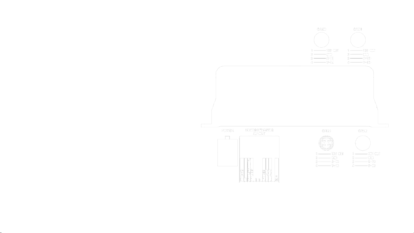
Rear Panel
7
Page 8
Remote Control
REMOTE KEYS
LOGIN Press to input your password and access setup screens
INFO View system information
Quad View (1,2,3,4)
RETURN Return to previous menu; exit from setup menu.
PAUSE/STEP Pause playing or play images at a single step. Press again to restore normal play speed.
FRAME Press to select a frame rate.
PLAY Press to start playing a video file.
FWD Forward key with four speeds: 2X,4X,8X,16X
REW Rewind key with four speeds: 2X,4X,8X,16X
NEXT Page down; go to next title.
PREV Page up; go to previous title.
PTZ Pan/Tilt/Zoom control
F1, F2, F3 Functional test keys.
Used to switch between quad view and single view; press the Quad View key to display 4 screens.
Press number 1/2/3/4 to display channel 1, 2,3, 4, respecvely
.
8
Page 9

Kit Contents
COMPONENTS
1 MDVR
2 Remote control
3 4G antenna
4 Camera cable(s)
5 GPS antenna
6 Display output cable
7 Power cable
8 I/O cable
9 Keys for HDD/SD/SIM door
10 Allan key
11 Hardware
9
Page 10
Installation
Installation Environment and Safety Precautions
To extend service life, attempt to install the device in a place where vibration is weak.
Do not install the device in a poorly-ventilated area (such as trunk).
The device must be installed horizontally in a location protected against water, humidity, and lightning.
8V-36V DC power supply is used for this device. Note the positive and negative terminals during connection to
prevent short circuit.
Always power the device off before connecting any peripheral.
Do not touch the power supply and the device with wet hands.
Do not spray liquid on the device to prevent internal short circuit or fire.
Do not place any other device directly on top of the camera.
To avoid damage or electric shock, do not disassemble the housing.
10
Page 11

Disclaimer
Subject to equipment availability, your system may vary slightly from the components described in this document, and may require the
use of adapters in order effect the connection of devices.
The connection instructions provided in this document are based on an in-house installation by FleetMind technical personnel and involve
the following components:
• RVS-5520 MDVR mobile HD DVR
• RVS-6139-RCA display with RCA connectors
11
Page 12

HDD, SIM Card, SD Card
To install the hard disk drive, SIM card, and SD card, you
must open the protective cover on the front panel of the
unit.
1. Turn the lock located on the front panel
counterclockwise to unlock it, and lift up the
protective cover.
2. Remove the HDD tray from its slot by squeezing the
tabs together and sliding the tray out.
12
Page 13

HDD, SIM Card, SD Card
3. Insert the HDD into the HDD
tray, and secure it with 4 screws
(provided), as shown.
4. Carefully insert the HDD by aligning
with the HDD slot until you hear a
"click" sound.
13
Page 14

HDD, SIM Card, SD Card
5. Insert the SIM card and the SD card into
their respective slots, as indicated on the
front panel. screws (provided), as shown.
6. Close the protective cover, and then turn the
lock clockwise to lock it, otherwise, the device
cannot be powered on.
WARNING! do not open the lock during normal operation,
otherwise the unit will shut down within 8 seconds.
14
Page 15
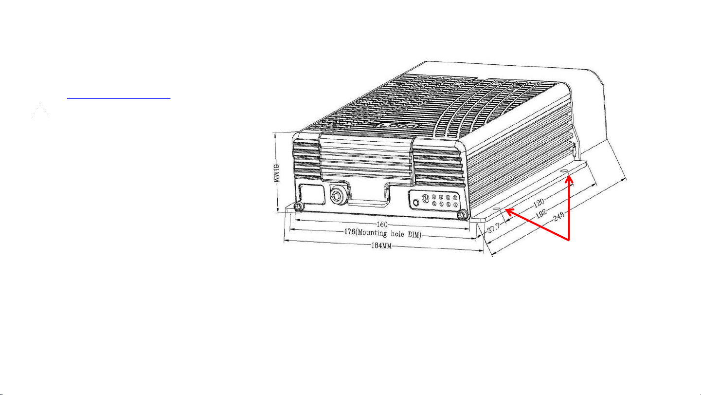
Mounting the Unit in the Vehicle
1. Decide on a suitable location for mounting
the MDVR in the vehicle, keeping in mind
the Installation Environment guidelines.
NOTE: Ensure that you leave sufficient
clearance for easy access to the rear panel
connectors.
2. Using the base plate of the unit as a
template, mark off the positions for the
mounting holes (4) and drill pilot holes
accordingly.
3. Fasten the MDVR to the surface with 4
screws.
Mounting holes
(2 on either side)
15
Page 16

Making Connections
Antennae
• Connect GPS, 3G/4G and Wi-Fi antennae to
their respective connectors on the rear panel
of the MDVR.
Power
1. Connect the power cable to the 6-pin power
input interface on the rear panel of the MDVR.
2. Connect the red and black wires to 12VDC and
ground, respectively.
3. Connect the yellow wire to ACC, the vehicle
control circuit switch (used to start the vehicle
motor).
The unit will be enabled automatically when
the car key is ON and disabled when the key is
OFF.
16
Page 17

Making Connections
Display
The MDVR supports two CVBS video outputs:
• the 3.5mm Phone Jack on the front panel
• the 24-PIN connector on the rear panel.
Use the pin-out diagram when connecting the display to the rear panel.
17
Page 18
Display - Rear Panel Connection
For rear panel connection, connect components as illustrated in
the figures below.
Align the arrows on each connector, insert, and
tighten the threaded collar.
MDVR
From 24-pin connector on MDVR
Cable from monitor
Adapter cable
18
Page 19

Display - Front Panel Connection
For Front Panel connection:
1. Connect the 3-in-1 terminal of the supplied
4pin-AV output cable to the 3.5mm phone jack
on the front panel of the MDVR
2. Connect the Audio (red) and Video (yellow)
connectors to the display unit.
MDVR 3-in-1 cable Display
19
Page 20

Sample Monitor Connection
20
Page 21

I/O Connections
Alarm Input and Output
Sensor Inputs
The 24-pin I/O connector on the rear panel provides 8 external alarm
inputs .
1. Connect the I/O cable to the rear panel connector,
2. Connect the alarm inputs to related sensor switching units, such
as door magnet power, emergency switch, turn signal switch and
brake light, as shown in the figure (right).
For example: the diagram (right) shows that high level is detected
when the brake pad is depressed; otherwise, low level will be
detected. Thus, braking may trigger a device alarm.
Overspeed Alarm
• If a speed is acquired from GPS, the alarm feature can be enabled
by simply configuring settings via Setup menu -> Alarm -> Speed.
• If speed is acquired from the vehicle, the over-speed alarm feature
can be enabled by connecting it to the speed pulse sensor. The
pulse sensor is connected to SPEED-A and SPEED-B cables of the
device, as shown in the figure (right).
21
Page 22

I/O Connections
Alarm Output
One alarm output using 200MA is provided to drive external alarm units. If you expect to drive a device with higher power, connect an external
electrical appliance, as shown in the following figure.
RS232/RS485 Device Connection
The 24-pin connector on the MDVR provides two RS232 serial ports, to which a
user can connect the desired sensor, OBD and two-way radio supporting RS232
according to actual requirements.
1. Connect the power cord and communication cable of the external device to
the supplied 24pin I/O port, and then to 24PIN I/O port on the rear panel of
the vehicle MDVR.
2. Install the probe for the external device.
22
Page 23

I/O Connections
PTZ (Pan/Tilt/Zoom)
There are three methods for setting up PTZ functionality:
1. Method 1 (Remote Control)
a) Connect the RS485 control cable of the PTZ to the RS485A
and RS485B of the MDVR, connect the video cable to the
MDVR video input, and then power the PTZ.
b) Configure the PTZ setting corresponding to PTZ data under
the peripheral setup option to use the remote control to
control the PTZ.
2. Method 2 (dedicated control unit)
a) Connect the RS485 control cable of the PTZ to 3D control
keypad.
b) Connect the video cable to the MDVR video input to power
the PTZ and 3D keypad.
c) Set keypad parameters corresponding to the PTZ.
Using a dedicated PTZ control unit may yield higher speed
and efficiency than the remote control.
3. Method 3 (both the above)
• Make the connections described for methods 1 and 2 to
enable PTZ functionality using both the remote control and
a dedicated control unit.
1
2
23
Page 24

Cameras
Connect your camera(s) as shown in the following figure.
Camera connections are keyed with tabs and slots to prevent improper connection.
1. Ensure that the slot of the camera cable is aligned with the tab on the camera
port CAM1 – CAM4.
2. Push connectors together, and then tighten the threaded collar on the cable.
The MDVR is equipped with DIN-4 connectors. Cameras with different types
of connectors (for example, BNC) will require the use of adapters.
24
Page 25

Setup Menus
After you have connected power to the vehicle start circuit, ensure
that the device will start automatically when the vehicle is started, and
that the
system enters the Quad View.
To access the setup menus:
• Press the Login key on your remote control and enter the Admin
password.
The Setup menu options display:
• General,
• Channel Mode,
• Record,
• Alarm,
• Tools,
• Peripherals,
• Search,
• System Info .
Quad View
Login Window
Setup menu
25
Page 26

Setup Menus
Basic Setup
From Setup menu, press the "ENTER" key to enter the General
interface, where you can set desired date and time, vehicle
information, user management, network and display.
26
Page 27

Set Date and Time
• From the Basic Setup menu, select Date &
Time.
1. It is advised to enable the auto-maintenance feature when the device is operating for a prolonged
time, so that the device automatically restarts within the set maintenance time.
2. OPR Timeout is the “quit automatically” time if the device is idle.
27
Page 28

Set Vehicle Info
1. From the Basic Setup menu, select Vehicle Info.
2. Enter all information and select Save when done.
28
Page 29

User Setup
The User Setup menu enables you to manage security, add and delete
users, and modify their access privileges.
1. From the Basic Setup menu, select User Setup.
The Security Setup menus displays.
2. Switch Password Enable on.
It is recommended that you change the password from the
default to a new one. Once the password is changed, you will use
the new password to enter the system setup menu.
3. Once you make all modifications, select Save.
29
Page 30

Network Setup
1. From the Basic Setup menu, select Network Setup.
The Security Setup menus displays.
2. Switch Password Enable on.
It is recommended that you change the password from the default to a new one.
Once the password is changed, you will use the new password to enter the system
setup menu.
3. Once you make all modifications, select Save.
NOTES:
• The two-way radio has port number 9988; this parameter is
unavailable for an analog two-way radio.
• A dynamic IP is assigned to the server, rather than a fixed IP,
"Domain Name" is selected as the connection mode. In this case,
a fixed IP is more stable; thus, it is not advised to use domain
name mode.
• You can establish your own server or use a server provided by the
manufacturer. If a server (including intercom server) provided by
the manufacturer is required, please contact our technical
support, which will provide the assigned device number, server
IP, related user account and password.
30
Page 31

Display Setup
1. From the General menu, select Display.
The Display Setup menus displays.
2. Set all parameters, and then select Save when done.
31
Page 32

Channel Mode
• From the Setup (root level) menu, select Channel Mode.
The Channel Mode menus displays.
This menu enables you to select different channel modes depending on
the model you use.
The device will restart when a mode is switched.
Several types of camera connections are supported . The interfaces for
the analog camera are defined as follows and the standard interface is
for the IP camera.
You can select the proper camera type and configure software according
to hardware connection mode.
32
Page 33

Channel Mode
33
Page 34

Record Setup
From the Record menu you can configure record settings, including general settings, main code,
sub-stream, recording schedule, mirror recording, SD recording, alarm recording, and IPC settings.
• From the Setup (root level) menu, select Record.
The Record menu displays.
Record Basic Setup
From the Record Basic setup menu, you can select the desired recording
mode as required. The record packet time can be set to 15 min, 30 min, 45
min or 60 min.
• To display the Record Basic setup menu, select Normal from the Record
menu.
34
Page 35

Record Basic Setup
When the alarm record option is selected, you can set the pre-record time, alarm record delay time, alarm output time
and alarm lock time. When timing record is selected, you can set the record schedule.
After setting, select Save.
35
Page 36

Main Code
From the Main code menu you can set the main code of the external analog
camera. Resolution D1/HD1/CIF/960H/720P are available
• From the Record menu, select Main Code.
• Enabling of the record feature requires an external pickup or the camera is provide with a pickup.
• If only IP camera input is selected, only IPC setting is required;
• After setting, select Save.
36
Page 37

Sub-Stream
Sub-stream settings are directly related to definition and fluency of video on the IVMS
platform. The higher the resolution, the frame rate and bit rate are, the higher the definition
of the video will be. However, this requires more memory and broadband consumption.
• From the Record menu, select Sub-Stream.
• Either CIF or QCIF is optional for sub-stream resolution. Currently, the maximum CIF real-time transmission can be realized for 3G
network;
• After setting, select Save.
37
Page 38

Recording Schedule
• From the Record menu, select Record Plan.
If "Timing Record" mode (not commonly used) is selected under record mode in the General
option, you can set the record time frame here (two time frames can be selected).
• The Recording Schedule is set only when the "Timing Record" mode is selected under record mode in the General option
• After setting, select Save.
38
Page 39

Mirror Record
Mirror recording provides backup recording for the MDVR in order to prevent loss of records
due to HDD error.
• From the Record menu, select Mirror.
• After changing settings, select Save.
39
Page 40

SD Record
SD recording enables you to record to the SD card instead of the HDD, in the event that of
HDD error.
• From the Record menu, select SD Rec.
• After changing settings, select Save.
40
Page 41

IPC
The IPC menu enables you to set parameters for IP camera recording.
• From the Record menu, select IPC.
When adding a camera, select the related channel, and you can manually input the IP
address and port number of the network camera, or click "Search" to select the desired
network camera in the search result.
The user name and password are set for the network camera. For a network camera with
security features, be the same as that for the network camera itself; or this setting can be
ignored. Use your remote controller to move to the latter you want, press "Enter" to
confirm your selection and press "Return" to return and complete your input.
• After changing settings, select Save.
41
Page 42

IPC
• IP address and port number are those for the network camera itself. Be sure to keep
them consistent when setting manually;
• Clicking on "Search" will list all IP cameras connected to the MDVR;
• Select Save when done.
42
Page 43

Alarm
The Alarm menu enables you to set sensor, speed, acceleration, temperature, motion detection,
ALARM OUT setting and other alarm modes.
• From the root-level setup menu, select Alarm.
The alarm feature can be used only when an external sensor is connected.
The alarm feature is enabled when the following settings are enabled.
• If "Event" is selected for alarm type. normal recording is conducted.
• If "Alarm" is selected, alarm recording is conducted; the threshold indicates the speed limit when the alarm is
triggered.
43
Page 44

Sensor
The MDVR supports 8 sensor-in channels. You can set the desired sensor names, as required from the
Sensor menu.
• From the Alarm setup menu, select Sensor.
• Output delay indicates that alarm output is set in the alarm ALARM OUT, i.e. when the alarm is off, the alarm
outputs within the set delay time.
• After setting, select Save.
44
Page 45

Speed
• From the Alarm setup menu, select Speed.
• Keep the signal stable when selecting GPS; connect the pulse sensor to the SPEED-A and SPEED-B. The speed can be
in KMH or MPH.
• After setting, select Save.
45
Page 46

G-Sensor
• From the Alarm setup menu, select G-Sensor.
• After setting, select Save.
46
Page 47

Temperature
• From the Alarm setup menu, select Temperature.
• After setting, select Save.
47
Page 48

Alarm Out
• From the Alarm setup menu, select Temperature.
You can select none/output 1/output2 from the ALARM OUT setup menu. 12V of high
level is generated to drive other opto-electronic devices when the related alarm is triggered.
(For detailed connection method, refer to alarm input/output cable connection.)
• After setting, select Save.
48
Page 49

Motion Detection
From the Motion Detection menu, you can select two points as diagonals to
define a detection area. Within the user defined area, when there is an
object moving, the system will issue an alarm.
You can search motion detection alarm events under "Configuration -> Log
Search", naming "CHL MD alarm".
• From the Alarm setup menu, select Motion.
To set the detection area:
1. Select the first block (yellow), and the motion block changes to blue after
pressing the "Enter" key.
2. Select the second block and press the "Enter" key. The rectangular area
formed by the diagonal of these two blocks is defined.
3. Select Return to return to the previous menu and press the Save key.
49
Page 50

Other Alarm
1. From the Alarm setup menu, select Other Alarm.
2. Set the timeout parking time and fatigue driving time
3. Select Save when done.
50
Page 51

Configuration
1. From the basic (root-level) setup menu, select Tools.
2. From the Tools menu, select Configure.
From the Configuration menu, you can import/export
configuration through USB or recover default configuration
NOTE: You must disable 3G and Wi-Fi before exporting, importing, and
upgrading logo.
51
Page 52

Format
1. From the Tools menu, select Format.
WARNING: FORMATTING WILL CLEAR ALL DATA STORED IN MEMORY.
EXERCISE CAUTION WHEN USING THIS FEATURE
52
Page 53

Log Search
1. From the Tools menu, select Log.
53
Page 54

Peripherals
1. From the root-level setup menu, select Peripherals.
From the Peripheral Setup menu, you can set PTZ, wireless broadband, Wi-Fi, Oil, and serial port parameters.
54
Page 55

PTZ
1. From the Peripherals setup menu, select PTZ Setup.
Use the default data bit, stop bit, and check code.
After setting the PTZ parameters, choose PTZ corresponding channels in order to switch using the remote control.
55
Page 56

Wireless
1. From the Peripherals setup menu, select Wireless Setup.
When a 3G/4G SIM card is used in the MDVR (1.e., information is
reported to the platform via
3G/4G), wireless dial-up must be enabled, and a proper
communication type must be selected according to operator's
network format.
There are some differences between 3G/4G software versions,
as shown in the above figures.
Use the default settings for domestic subscribers. (The figures
show default settings for China Unicom and China Telecom. For
other subscribers, fill these fields with information provided by
your local mobile network operator. )
After exiting from all menus, pressing the INFO button on
the remote control will show all 3G/4G-specific
information. If the signal is normal, the dial-up operation is
successful
3G Software
4G Software
56
Page 57

Wi-Fi
1. From the Peripherals setup menu, select Wi-Fi Setup.
The Wi-Fi menu enables you to specify IP, SSID, and submask of your Wi-Fi. The device will verify that the RJ45 is successfully connected to the
external module.
57
Page 58

Oil
1. From the Peripherals setup menu, select Oil.
This feature can be enabled only when an external oil level sensor is connected and the enable feature is on. Coefficient = total capacity of the oil
tank (X)
Coefficient = total capacity of the oil tank (X)/height (mm) *100%.
58
Page 59

Serial Device Setup
1. From the Peripherals setup menu, select Serial.
This setting requires connection to the associated serial device. You can set parameters according to the related serial device settings. In general,
default settings are used.
After an external RS232 device is connected, related sensor features can be used only when serial port 1 or serial port 2 is set to the serial device
name.
59
Page 60

Record Search
1. From the main (root-level) setup menu, select Search.
60
Page 61

System Info
In Quad View mode, you can either press the INFO key on your
remote control or enter the setup menu to display the system
information.
61
Page 62

Monitor
RVS-6139-RCA
62
Page 63

Controls
63
Page 64

Dimensions
Front Panel
Rear Panel
64
Page 65

Specifications
65
Page 66

Before Beginning Installation
66
Page 67

Installation
67
Page 68

Installation
68
 Loading...