

Page 1

Rear View Safety, Inc. © 2018
Page 2
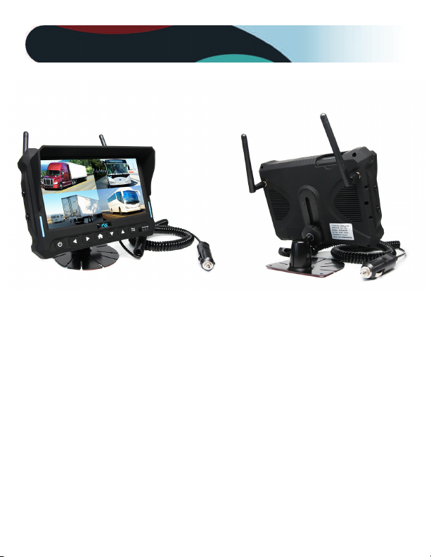
What’s in the Box?
• 1 x 7" Quad View Monitor With Built-In DVR and Sunshade
• 1 x Universal Mount With Adhesive Pad
• 2 x Wireless Antennas
Page 3

Table of Contents
Introduction.................................................................................................. 4
Safety Information ................................................................................. 57
Before Beginning Installation.................................................................. 8
Installation Guide........................................................................................ 9
Monitor ........................................................................................................10
System Operation.......................................................................................11
Pairing ..........................................................................................................12
Recording.....................................................................................................13
Screen Rotation ......................................................................................14
Image Settings ...........................................................................................15
Playback / Audio ........................................................................................16
Grid Lines ...............................................................................................17
Camera Placement System .....................................................................18
Monitor Specifications ............................................................................19
Camera Placement .................................................................................... 20
Troubleshooting ....................................................................................... 21
Warranty .................................................................................................... 22
Disclaimer .................................................................................................. 23
3
Page 4

Introduction
Congratulations on purchasing a Rear View Backup Camera
Syste! With this manual you will be able to properly install and
operate the unit.
The Backup Camera System is intended to be installed as a
supplement aid to your standard rear view mirror that already ex
ists in your vehicle. The Backup Camera System should not be
used as a substitute for the standard rear view mirror or for any
other mirror that exists in your vehicle.
In some jurisdictions, it is unlawful for a person to drive a
motor vehicle equipped with a TV viewer or screen located for
ward of the back of the driver’s seat or in any location that is vis
ible, directly or indirectly, to the driver while operating the
vehicle.
4
REAR VIEW SAFETY
Page 5

Safety Information
Please read the entire manual and follow the instructions and
warnings carefully. Failure to do so can cause serious damage
and/or injury, including loss of life. Be sure to obey all applica
ble local traffic and motor vehicle regulations as it pertains to
this product. Improper installation will void manufacturer’s
warranty.
USAGE
• The Rear View Camera System
is designed to help the driver
safely detect people and/or
objects helping to avoid
damage or injury. However,
you the driver, must use it
properly. Use of this system is
not a substitute for safe,
proper or legal driving.
• Never back up while looking
at the monitor alone. You
should always check behind
and around the vehicle when
backing up, in the same way
as you would if the vehicle
did not have the Rear View
Reverse With Confidence
™
Camera System. If you back
up while looking only at the
monitor, you may cause
damage or injury. Always
back up slowly.
• The Rear View Camera
System is not intended for
use during exstensive backup
maneuvers or backing into
cross traffic or pedestrian
walkways.
• Please, always remember,
the area displayed by the
Rear View Camera System is
limited. It does not display
the entire panorama that is
behind you.
5
Page 6

Safety Information
INSTALLA TION
• Electric shock or product
malfunction may occur if
this product is installed
incorrectly.
• Use this product within
the voltage range specified.
Failure to do so can cause
electronic shock or product
malfunction.
• Take special care when
cleaning the monitor.
• Make sure to firmly affix the
product before use.
• If smoke or a burning smell
is detected, disconnect the
system immediately.
• Where the power cable may
touch a metal case, cover the
cable with a friction tape. A
short circuit or disconnected
wire may cause a fire.
• While installing the Rear
View System be careful with
the wire positioning in order
to avoid wire damage.
• The Rear View System
should only be used when
the vehicle is in reverse.
• Do not watch movies or
operate the monitor while
driving; as it may cause an
accident.
• Do not install the monitor
where it may obstruct drivers
view or obstruct an air bag
device.
• Dropping the unit may cause
possible mechanical failure.
6
REAR VIEW SAFETY
Page 7

Safety Information
If you have questions about this product, contact:
Customer Service:
Rear View Safety
1797 Atlantic Avenue
Brooklyn, NY 11233
Tel: 1.800.764.1028
IN NO EVENT SHALL SELLER OR MANUFACTURER BE
LIABLE FOR ANY DIRECT OR CONSEQUENTIAL DAMAGES OF
ANY NATURE, OR LOSSES OR EXPENSES RESULTING FROM
ANY DEFECTIVE PRODUCT OR THE USE OF ANY PRODUCT.
Reverse With Confidence
™
7
Page 8

Before Beginning Installation
Before Beginning Installation
Before drilling please check that no cable or wiring is on the
other side of the wall. Please clamp all wires securely to reduce
the possibility of them being damaged while vehicle is in use.
Keep all cables away from hot or moving parts and electrical
noisy components.
Step 1: Choose the monitor and camera locations.
Step 2: Install all cables in vehicle, when necessary a 0.8
(20mm) hole should be drilled for passing camera cable through
vehicles walls. Install split grommets where applicable.
Step 3: Once all cables and wiring have been properly routed
and the system has paired, perform a system function test by
temporarily connecting the system. If the problem persists see
troubleshooting (page 20).
We recommend doing a benchmark test before installation
to insure that all components are working properly.
8
REAR VIEW SAFETY
Page 9

Installation Guide
Camera Connection:
• Locate the clearance lights wiring on your vehicle. You may need
to remove the interior panel in order to locate. Connect the power
cables for camera: Red wire to light's positive; Black wire to chassis
ground.
Monitor Connection:
• Cigarette lighter adapter: Firmly insert the lighter plug to ciga
rette lighter socket.
• Loose lead wire: To power the system connect the power (RED) 12V
+ wire to ignition power and the ground (BLACK) wire to the chassis
ground. These are
power and "arrow" keys to toggle between different views.
Three positive trigger wires (BLUE-CH2, YELLOW-CH3, WHITE-CH4)
represent a channel and activate when trigger wire connectS to 12V.
• "CAM2" is the designated backup channel. To have the the backup
camera display when going in reverse, connect the BLUE wire to
reverse power (or any power source that comes on only in reverse).
The other channels can similarly be triggered (i.e. side cameras can
be triggered by the turn signals, etc.)
DO NOT INSTALL monitor where it may obstruct driver view or
obstruct air bag devices.
the only wires needed to power the system. Press
Reverse With Confidence
™
9
Page 10

Monitor
CAMERA
SELECTION
DOWN
ARROW
MENU/
SELECTION
BUTTON
POWER
ON /OFF
10
HOME
UP
ARROW
BACK
REAR VIEW SAFETY
Page 11

System Operation
System Operation: To turn on the monitor, press
“POWER ON” button.
To get to Main Menu, press “Home” button use the up
and down arrows to navigate the menu and use the
"Home" button to confirm your selection.
To go back, press the "REV" (arrows) button. To adjust
the volume, use the up and down arrows while viewing
the camera
Reverse With Confidence
™
1
1
Page 12

Pairing
Pairing
1. Use the "right and left" arrow buttons to toggle through the
channels and select the channel you want to pair to.
2. Press "Home" to open the menu and press "Home" again to
initiate "pairing mode". You will see the system start counting
down from 50 seconds. Once "pairing mode" is active it will
last for 50 seconds.
3. Press the pair button on the back of the camera within the
50 seconds and the camera image will appear on the monitor.
The system is paired. NOTE: Please make sure the camera is
receiving power when you pair. TIP: If the 50 second countdown
does not appear, be sure to press the menu button lightly.
12
REAR VIEW SAFETY
Page 13

Recording
Recording: System has capabilities to record all 4 cameras. To start
recording, insert a Memory card into the slot on the top of the
monitor.
You will need to format the card which can be done in the
"RECORD" option in the menu. After formatting, choose the
channel you want to record and turn it on.
When the channel is turned on, the camera will begin recording
when the system is powered on.
Overwrite option allows system to continuously record while
overwriting the oldest footage.
13
REAR VIEW SAFETY
Page 14

Screen Rotation
There are advantages to rotating a screen either vertically or
horizontally. Different views include :
Standard Display
Horizontal Reverse
Vertical Reverse
Hand V Reverse
Reverse With Confidence
- Display in classic view
- Display flipped Horizontally
- Display flipped Vertically
- Display flipped Vertically + Horizontally
™
14
Page 15

Image Settings
Image Settings: The image can be modified to the driver's
specifications. Easily adjust the Brightness, Contrast, and
Color to create the optimal brightness..
15
REAR VIEW SAFETY
Page 16

Playback / Audio
Playback:
For playback, select the "PLAYBACK option in the menu and
the "HOME" button to select the file you want to play
use
back. The "HOME button also serves and the pause button.
Audio:
CAM2 is the audio enabled channel. When using a
cigarette lighter, audio will be automatically activated. When
using loose lead connections the blue wire must be receiving 12V
to activate audio.
Reverse With Confidence
™
16
Page 17

Grid Lines
Grid-lines: The gridlines will appear on CAM2. With the
cigarette lighter connection the gridlines can be turned on/off
through the menu. With the loose lead connections the grid
lines are controlled with the reverse trigger wire. When this
wire is receiving 12V power the gridlines will appear.
17
REAR VIEW SAFETY
Page 18

System Camera Placement
Reverse With Confidence
™
18
Page 19

Monitor Specifications
TFT LCD Digital Monitor
Screen Size 7”
Dot Resolution 800
H x 3 (RGB) 480V
Display Format 16:9 / 500:1
Display Brightness 400cd/m
2
Viewing Angle U:50° / D:60° / R:70°
Video Input 4 channel
Video Source 1Vpp, 75Ω
Power Supply DC 12V(+/ 10%)
Power Consumption 5W
Operating Temperature 30°C ~ +80° C
Video System Auto NTSC/PAL
Overall Dimensions 7”
L x 5”H x 1”D
Weight 400G
Impact Rating 5G
Dot Pitch 0.192
H x 0.1805V
Sync System Internal
Weight 520g
Reverse With Confidence
™
19
Page 20

Camera Positioning
Reverse With Confidence
™
20
Page 21

Troubleshooting
Monitor Displays Blue Screen & Displays No Signal
• Do a hard reset, unplug all
cables and power cables leave
out for 1 minute and then
reconnect them.
No Image On Screen
• Verify camera is on correct
camera input
Signal Issues
• The antenna booster is an
extendable antenna that can be
used in case of signal issues.
• Check to ensure that the con
nection to the camera is tight.
• Verify camera is connected
to power/ground
• The cable is attached just like
the standard antenna by
screwing on the connection
The antenna itself is attached
magnetically.
21
REAR VIEW SAFETY
Page 22

Warranty
One Year Warranty
Rear View Safety, Inc. warrants this product against material defects
for a period of one year from date of purchase. We reserve the right
to repair or replace any such defective unit at our sole discretion.
Rear View Safety, Inc. is not responsible for a defect in the system as
a result of misuse, improper installation, damage or mishandling of
the electronic components. Rear View Safety, Inc. is not responsible
for consequential damages of any kind.
This warranty is void if: defects in materials or workmanship or damages result from
repairs or alterations which have been made or attempted by others or the unautho
rized use of nonconforming parts; the damage is due to normal wear and tear, this
damage is due to abuse, improper maintenance, neglect or accident; or the damage is
due to use of the Rear View Safety, Inc. system after partial failure or use with im
proper accessories.
Warranty Performance
DURING THE ABOVE WARRANTY PERIOD, SHOULD YOUR Rear View Safety
PRODUCT EXHIBIT A DEFECT IN MATERIAL OR WORKMANSHIP, SUCH DEFECT
WILL BE REPAIRED WHEN THE COMPLETE Rear View Safety, INC. PRODUCT IS
RETURNED, POSTAGE PREPAID AND INSURED, TO Rear View Safety, INC.
OTHER THAN THE POSTAGE AND INSURANCE REQUIREMENT, NO CHARGE
WILL BE MADE FOR REPAIRS COVERED BY THIS WARRANTY.
Warranty Disclaimers
NO WARRANTY, ORAL OR WRITTEN, EXPRESSED OR IMPLIED, OTHER THE
ABOVE WARRANTY IS MADE WITH REGARD TO THIS Rear View Safety, INC.
Rear View Safety, INC. DISCLAIMS ANY IMPLIED WARRANTY OR MERCHANT
ABILITY OR FITNESS FOR A PARTICULAR USE OR PURPOSE AND ALL OTHER
WARRANTIES IN NO EVENT SHALL Rear View Safety. INC. LIABLE FOR ANY IN
CIDENTAL, SPECIAL, CONSEQUENTIAL, OR PUNITIVE DAMAGES OR FOR ANY
COSTS, ATTORNEY FEES, EXPENSES, LOSSES OR DELAYS ALLEGED TO BE AS A
CONSEQUENCE OF ANY DAMAGE TO, FAILURE OF, OR DEFECT IN ANY PROD
UCT INCLUDING, BUT NOT LIMITED TO, ANY CLAIMS FOR LOSS OF PROFITS.
Reverse With Confidence
™
22
Page 23

Disclaimer
Rear View Safety and/or its affiliates does not guarantee or promise
that the user of our systems will not be in/part of an accident or
otherwise not collide with an object and/or person. Our systems are
not a substitute for careful and cautious driving or for the consistent
adherence to all applicable traffic laws and motor vehicle safety
regulations. The Rear View Safety products are not a substitute for
rearview mirrors or for any other motor vehicle equipment mandated
by law. Our camera systems have a limited field of vision and do not
provide a comprehensive view of the rear or side area of the vehicle.
Always make sure to look around your vehicle and use your mirrors
to confirm rearward clearance and that your vehicle can maneuver
safely. Rear View Safety and/or its affiliates shall have no responsi
bility or liability for damage and/or injury resulting from accidents
occurring with vehicles having some of Rear View Safety products
installed, and Rear View Safety and/or its affiliates, the manufac
turer, distributor and seller shall not be liable for any injury, loss or
damage, incidental or consequential, arising out of the use or in
tended use of the product. In no event shall Rear View Safety and/or
its affiliates have any liability for any losses (whether direct or indi
rect, in contract, tort or otherwise) incurred in connection with the
systems, including but not limited to damaged property, personal in
jury and/or loss of life. Neither shall Rear View Safety and/or its af
filiates have any responsibility for any decision, action or inaction
taken by any person in reliance on Rear View Safety systems, or for
any delays, inaccuracies and/or errors in connection with our sys
tems functions.
23
REAR VIEW SAFETY
Page 24

If you have any questions
about this product, contact:
Rear View Safety, Inc.
1797 Atlantic Avenue
Brooklyn, NY 11233
800.764.1028
BETTER CAMERAS. BETTER SERVICE.
IT’S OUR GUARANTEE.
 Loading...