

Page 1
Instruction Manual
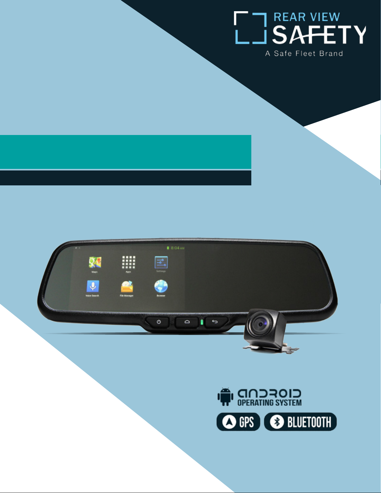
G-SERIES Backup Camera System
with 5” Android Operated Display
RVS-776718-5
Reverse With Condence ™
Rear View Safety, Inc. © 2017
1
Page 2
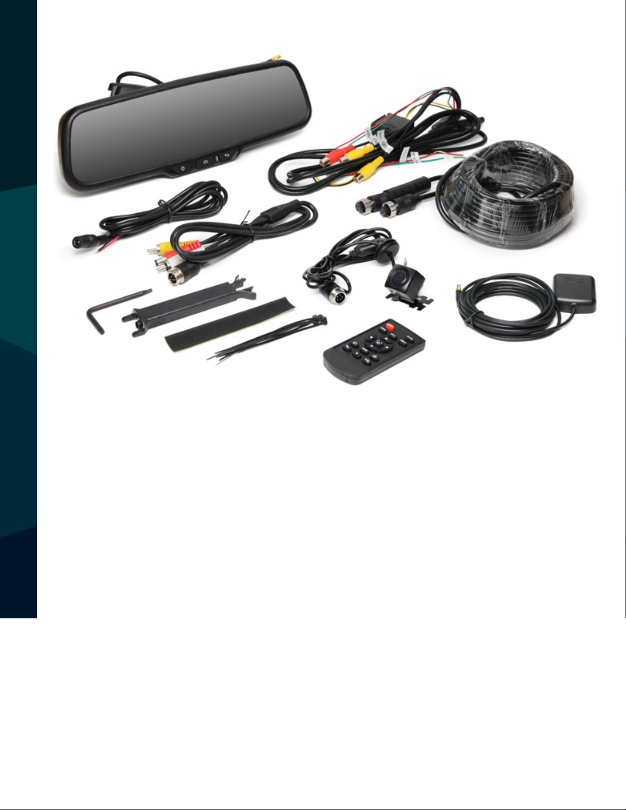
TABLE OF CONTENTS
Introduction...............................03-05
Safety Information..........................06-08
Before Beginning Installation . . . . . . . . . . . . . . . . . . . . . . . 09
Installation Guide.......................... 10-11
Adjustable Grid Line...........................10
Installation and Wire.........................11-16
Basic Functions. ...........................17-20
Monitor Specications ..........................21
Camera Specication. ..........................22
Camera Installation ...........................23
Troubleshooting.............................24
Warranty & Disclaimer........................ 25-26
2
Rear View Safety
Page 3

NOTE!
Please read all of the installation instructions
carefully before installing the product. Improper
installation will void manufacturer’s warranty.
Congratulations on purchasing a Rear View Backup
Camera System!
With this manual you will be able to properly install and
operate the unit.
The Backup Camera System is intended to be installed as a
supplement aid to your standard rear view mirror that already exists
in your vehicle. The Backup Camera System should not be used as a
substitute for the standard rear view mirror or for any other mirror
that exists in your vehicle.
In some jurisdictions, it is unlawful for a person to drive a
motor vehicle equipped with a TV viewer or screen located forward of
the back of the driver’s seat or in any location that is visible, directly
or indirectly, to the driver while operating the vehicle.
INTRODUCTION
Reverse With Condence ™
3
Page 4
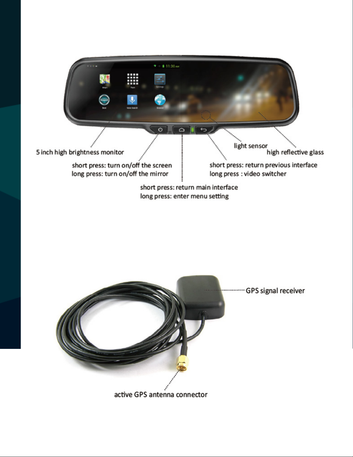
Function of Buttons
GPS Antenna and Cable
INTRODUCTION
4
Rear View Safety
Page 5
INTRODUCTION
Reverse With Condence ™
5
Page 6

Please read the entire manual and follow the instructions and
warnings carefully. Failure to do so can cause serious damage and/or
injury, including loss of life. Be sure to obey all applicable local
trac and motor vehicle regulations as it pertains to this product.
Improper installation will void manufacturer’s warranty.
USAGE:
• The Rear View Camera System is
designed to help the driver safely detect people and/or objects,
helping to avoid damage or injury.
However, you the driver, must use it
properly. Use of this system is not a
substitute for safe, proper or legal
driving.
• Never back up while looking at the
monitor alone. You should always
damage or injury. Always back up
slowly.
• The Rear View Camera System is
not intended for use during extensive back-up maneuvers or backing
into cross trac or pedestrian walkways.
•Please, always remember, the area
displayed by the Rear View Camera
check behind and around the vehi-
SAFETY INFORMATION
cle when backing up, in the same
way as you would if the vehicle did
not have the Rear View Camera
System. If you back up while looking
only at the monitor, you may cause
6
System is limited. It does not display
the entire panorama that is behind
you.
Rear View Safety
Page 7

INSTALLATION:
• Electric shock or product
malfunction may occur if this
product is installed
incorrectly.
• Use this product within
the voltage range specied. Failure
to do so can cause
electronic shock or product
malfunction.
or disconnected wire may cause a
re.
• While installing the Rear View
System be careful with the wire
positioning in order to avoid wire
damage.
• The Rear View System should only
be used when the vehicle is in
reverse.
SAFETY INFORMATION
• Take special care when
cleaning the monitor.
• Make sure to rmly ax the prod-
uct before use.
• If smoke or a burning smell
is detected, disconnect the
system immediately.
• Where the power cable may touch
• Do not watch movies or
operate the monitor while driving;
as it may cause an
accident.
• Do not install the monitor
where it may obstruct the driver’s
view or obstruct an air bag
device.
a metal case, cover the cable with
friction tape. A short circuit
Reverse With Condence ™
• Dropping the unit may cause
possible mechanical failure.
7
Page 8
If you have questions about this product, contact:
A Safe Fleet Brand
Rear View Safety
1797 Atlantic Avenue
Brooklyn, NY 11233
Tel: 1.800.764.1028
IN NO EVENT SHALL SELLER OR MANUFACTURER BE
SAFETY INFORMATION
LIABLE FOR ANY DIRECT OR CONSEQUENTIAL DAMAGES OF
ANY NATURE, OR LOSSES OR EXPENSES RESULTING FROM
ANY DEFECTIVE PRODUCT OR THE USE OF ANY PRODUCT.
8
Rear View Safety
Page 9

Before drilling please check that no cable or wiring is on the other side
of the wall. Please clamp all wires securely to reduce the possibility
of them being damaged while vehicle is in use. Keep all cables away
from hot or moving parts and electrical noisy components.
We recommend doing a benchmark test before installation
to insure that all components are working properly.
Step 1: Choose the monitor and camera locations.
Step 2: Install all cables in vehicle, when necessary a 0.8 (20mm)
hole should be drilled for passing camera cable through vehicles
walls. Install split grommets where applicable.
Step 3: Once all cables and wiring have been properly routed, perform
a system function test by temporarily connecting the system. If the
system seems to not be operating properly see troubleshooting (page
24).
BEFORE YOU BEGIN
Reverse With Condence ™
9
Page 10

Replacement Monitor
The mirror monitor replaces the existing car mirror. Carefully remove
the mirror o the “pin”. Slide the replacement mirror on to the pin and
secure it with the screw provided (already in the screw hole).Dierent cars have dierent brackets. Depending on your vehicle make and
manufacturer. There are many methods to remove the original rearview mirror, however, please don’t force the mirror o the bracket.
The manufacturer will not be responsible for damage caused to your
car by wrong installation of the mirror. Figure 1.1
Clip-On Monitor
1. The Mirror Monitor attaches to the existing rear view mirror in
vehicle with the pressurized clips on the back of the monitor.
2. Attach monitor to existing mirror, and adjust mounting angle to
allow optimum driver viewing comfort.
Camera & Cable
Be sure to position the cable properly. The aviation camera cable uses
INSTALLATION GUIDE
aircraft grade connectors which means the camera cable can be exposed to all weather elements. Do not run the cable over sharp edges,
do not kink the cable and keep away from HOT and rotating parts.
Fasten all cables and secure all excess cable. Connect camera to the
10
camera extension cable which runs inside the vehicle. Figure 1.2
Rear View Safety
Page 11

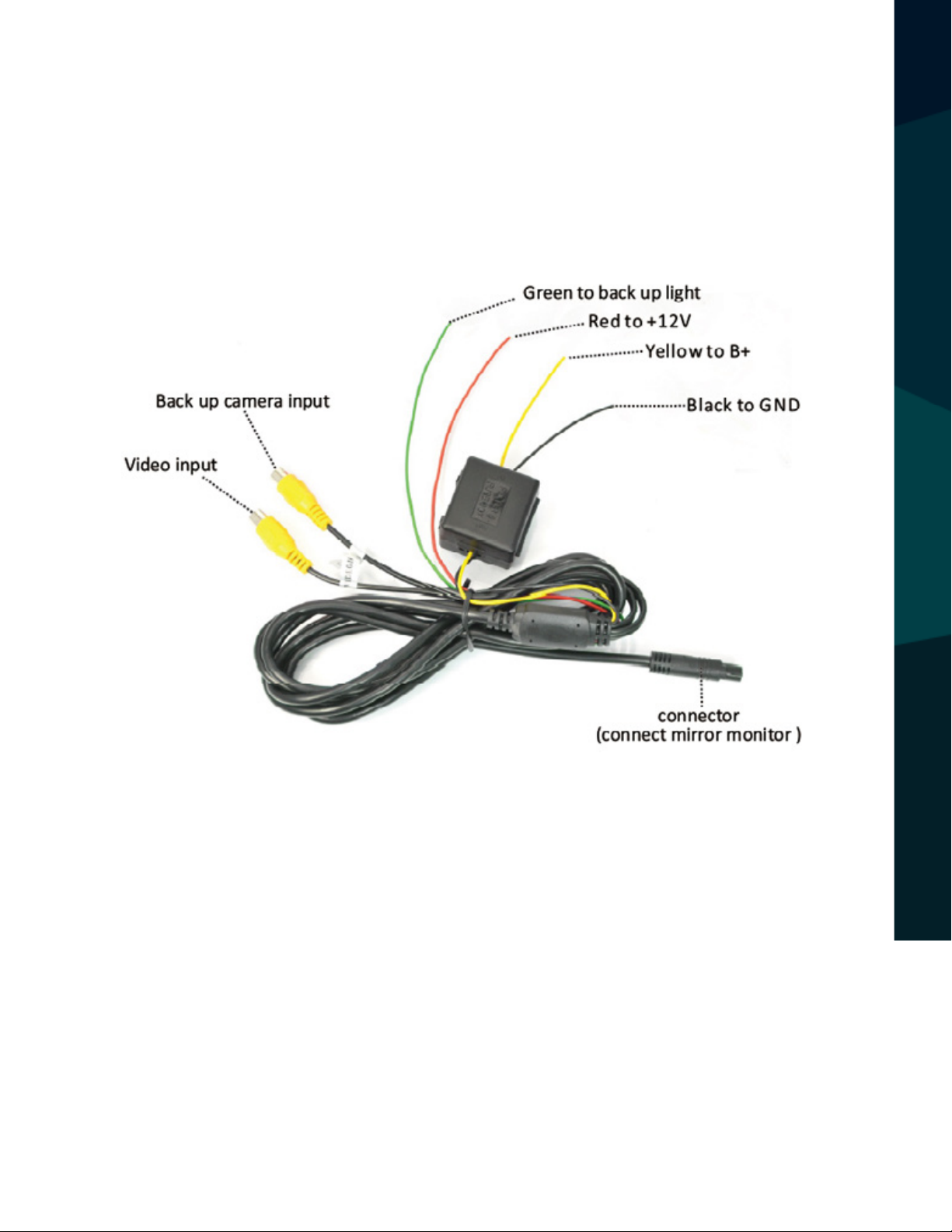
Wiring
After connecting the camera to the “camera cable” the camera should
be plugged into AV2 input. Connect the RED 12V power wire to an
ignition power source, and the BLACK 12V ground wire to a chassis
ground. The GREEN wire is the REVERSE trigger wire. Connect this wire
to the vehicle’s backup light circuit to activate the rear-view image
whenever the vehicle shifts into reverse. To connect a second camera,
connect it to AV1 input. It can be turned on by pressing the power button on the monitor. Figure 2.1, Figure 2.2
Precautions for use of Mirror Monitor
I. The Mirror Monitor is made of glass. Do not subject it to a
mechanical shock by dropping it from a high place, etc.
II. Do not apply excessive force to the monitor surface or the
adjoining areas since this may cause the color tone to vary.
III. Clean with a soft dry cloth and/or Windex only.
IV. Do not attempt to disassemble the mirror monitor.
INSTALLATION GUIDE + TIPS
Safety
• Before drilling, be sure no cable or wire is on the other side.
• Feed as much cable as possible into vehicle & clamp securely.
This reduces the possibility of cable being hooked or snagged.
Reverse With Condence ™
11
Page 12

Grid Lines
Generally, to help drivers estimate the distance from obstacles, there are
three lines for reference- red, yellow, and green. Those three lines are displayed on the monitor when car is reversing. The green line is 3M from the
back of the car and the yellow line is 6.5 ft. The distant red line is 1M from
the backside of car while the close red line is 0.4M. Both reference lines on
the left and right should leave 0.2M space from the car.
Accuracy
ADJUSTABLE GRID LINE
The accuracy of the grid-lines can vary based on how you angle your camera. Therefore to compensate for inaccuracies, you can adjust the grid-lines
to your camera angle.
12
Rear View Safety
Page 13

FIGURE 1.1
FIGURE 1.2
INSTALLATION AND WIRE
Reverse With Condence ™
13
Page 14

How to Wire
FIGURE 2.1
HOW TO WIRE + SPLICING
14
Rear View Safety
Page 15

HOW TO WIRE + SPLICING
Reverse With Condence ™
15
Page 16

FIGURE 2.2
HOW TO WIRE + SPLICING
16
Rear View Safety
Page 17

Highly Reective Mirror
In addition to being a monitor, the system is also a highly reective mirror.
Highly reective mirror
Normal mirror
Back up Camera Display
When the car is put into reverse, the monitor will automatically display the
backup camera.
BASIC FUNCTIONS
Reverse With Condence ™
17
Page 18

Main Menu
There are 6 icons on the main menu interface. They are easy to use and can
be changed based on preference. The icons are the same as those on an
Android cellphone.
Booting APP Setting
Applications can be set to automatically boot up when the mirror is turned
on.
Press to enter the app list, and press for auto-boot menu.
BASIC FUNCTIONS
18
Rear View Safety
Page 19

Up to ve applications can be set to automatically start. The user can also
control how long the app will remain on if inactive after startup, as well as
if the app will start running in the foreground or background. Applications
can also be deleted from the auto-boot list in this display.
Series number (auto-boot up to 5 apps)
Add time
Time display (How long app will stay on if inactive)
DVR Recorder
Subtract time
BASIC FUNCTIONS
Forground/background app toggle
Delete application from auto-boot list
Add application
Currently running application
Certain versions of this system are equipped with DVR capabilities. Simply sign into a Google account and download a DVR recorder application.
Please note: A forward facing camera is required in order to use this feature. Only available through custom order.
Reverse With Condence ™
19
Page 20

Mapping Data
Though mapping data is not included with this system, users may download or buy navigation software.
BASIC FUNCTIONS
20
Rear View Safety
Page 21

3”
About Our Monitor
10.25”
MONITOR SPECIFICATIONS
SPECIFICATIONS:
Screen Size:
Display Screen:
Display Resolution:
Aspect Ratio:
Color Depth:
Pixel Pitch (mm)
Power Consumption:
Working Voltage:
Video Input:
4.3”
TFT-LCD
400(H)x234(V)
16:9
16.7M dithering
0.219x0.219
8W
DC12V
VIDEO-IN to GPS/DVD
(Default) Camera to backup camera
Signal System:
PAL/Auto/NTSC
Reverse With Condence ™
21
Page 22

About Camera
CAMERA SPECIFICATIONS
SPECIFICATIONS:
22
Rear View Safety
Page 23

Camera Installation
170
º
installation
CAMERA INSTALLATION
Mounting Position
view angle
position
Reverse With Condence ™
23
Page 24

No Image On Screen
• Do a hard reset, unplug all cables
and power cables, leave out for 1
minute and then re-connect them
• Check to ensure that the
connection to the camera is tight
• Verify camera cable is plugged into
port labeled Backup Camera
• Verify that the green positive
• Verify camera is on correct camera
input
• Verify cable is connected to
monitor
• Verify camera is connected to
cable
• Connect known working camera
and cable to monitor
trigger on power harness is put to
power 12v+
TROUBLESHOOTING
• Verify green trigger is receiving
power
24
Rear View Safety
Page 25

ONE YEAR WARRANTY
REAR VIEW SAFETY, INC. WARRANTS THIS PRODUCT AGAINST MATERIAL DEFECTS FOR A
PERIOD OF ONE YEAR FROM DATE OF PURCHASE. WE RESERVE THE RIGHT TO REPAIR OR
REPLACE ANY SUCH DEFECTIVE UNIT AT OUR SOLE DISCRETION. REAR VIEW SAFETY, INC.
IS NOT RESPONSIBLE FOR A DEFECT IN THE SYSTEM AS A RESULT OF MISUSE, IMPROPER
INSTALLATION, DAMAGE OR MISHANDLING OF THE ELECTRONIC COMPONENTS. REAR VIEW
SAFETY, INC. IS NOT RESPONSIBLE FOR CONSEQUENTIAL DAMAGES OF ANY KIND.
THIS WARRANTY IS VOID IF: DEFECTS IN MATERIALS OR WORKMANSHIP OR DAMAGES
RESULT FROM REPAIRS OR ALTERATIONS WHICH HAVE BEEN MADE OR ATTEMPTED BY
OTHERS OR THE UNAUTHORIZED USE OF NONCONFORMING PARTS; THE DAMAGE IS DUE
TO NORMAL WEAR AND TEAR, THIS DAMAGE IS DUE TO ABUSE, IMPROPER MAINTENANCE,
NEGLECT OR ACCIDENT; OR THE DAMAGE IS DUE TO USE OF THE REAR VIEW SAFETY, INC.
SYSTEM AFTER PARTIAL FAILURE OR USE WITH IMPROPER ACCESSORIES.
WARRANTY PERFORMANCE
DURING THE ABOVE WARRANTY PERIOD, SHOULD YOUR REAR VIEW SAFETY PRODUCT
EXHIBIT A DEFECT IN MATERIAL OR WORKMANSHIP, SUCH DEFECT WILL BE REPAIRED WHEN
THE COMPLETE REAR VIEW SAFETY, INC. PRODUCT IS RETURNED, POSTAGE PREPAID AND
INSURED, TO REAR VIEW SAFETY, INC. OTHER THAN THE POSTAGE AND INSURANCE
REQUIREMENT, NO CHARGE WILL BE MADE FOR REPAIRS COVERED BY THIS WARRANTY.
WARRANTY DISCLAIMERS
NO WARRANTY, ORAL OR WRITTEN, EXPRESSED OR IMPLIED, OTHER THE ABOVE WARRANTY
IS MADE WITH REGARD TO THIS REAR VIEW SAFETY, INC. REAR VIEW SAFETY, INC. DISCLAIMS
ANY IMPLIED WARRANTY OR MERCHANTABILITY OR FITNESS FOR A PARTICULAR USE OR
PURPOSE AND ALL OTHER WARRANTIES IN NO EVENT SHALL REAR VIEW SAFETY. INC.
LIABLE FOR ANY INCIDENTAL, SPECIAL, CONSEQUENTIAL, OR PUNITIVE DAMAGES OR FOR
ANY COSTS, ATTORNEY FEES, EXPENSES, LOSSES OR DELAYS ALLEGED TO BE AS A
WARRANTY
CONSEQUENCE OF ANY DAMAGE TO, FAILURE OF, OR DEFECT IN ANY PRODUCT INCLUDING,
BUT NOT LIMITED TO, ANY CLAIMS FOR LOSS OF PROFITS.
Reverse With Condence ™
25
Page 26

DISCLAIMER
REAR VIEW SAFETY AND/OR ITS AFFILIATES DOES NOT GUARANTEE OR PROMISE THAT THE
USER OF OUR SYSTEMS WILL NOT BE IN/PART OF AN ACCIDENT OR OTHERWISE NOT COLLIDE
WITH AN OBJECT AND/OR PERSON. OUR SYSTEMS ARE NOT A SUBSTITUTE FOR CAREFUL
AND CAUTIOUS DRIVING OR FOR THE CONSISTENT ADHERENCE TO ALL APPLICABLE TRAFFIC
LAWS AND MOTOR VEHICLE SAFETY REGULATIONS. THE REAR VIEW SAFETY PRODUCTS ARE
NOT A SUBSTITUTE FOR REARVIEW MIRRORS OR FOR ANY OTHER MOTOR VEHICLE
EQUIPMENT MANDATED BY LAW. OUR CAMERA SYSTEMS HAVE A LIMITED FIELD OF VISION
AND DO NOT PROVIDE A COMPREHENSIVE VIEW OF THE REAR OR SIDE AREA OF THE VEHICLE.
ALWAYS MAKE SURE TO LOOK AROUND YOUR VEHICLE AND USE YOUR MIRRORS TO CONFIRM
REARWARD CLEARANCE AND THAT YOUR VEHICLE CAN MANEUVER SAFELY. REAR VIEW
SAFETY AND/OR ITS AFFILIATES SHALL HAVE NO RESPONSIBILITY OR LIABILITY
FOR DAMAGE AND/OR INJURY RESULTING FROM ACCIDENTS OCCURRING WITH VEHICLES
HAVING SOME OF REAR VIEW SAFETY PRODUCTS INSTALLED AND REAR VIEW SAFETY AND/
OR ITS AFFILIATES, THE MANUFACTURER, DISTRIBUTOR AND SELLER SHALL NOT BE LIABLE
FOR ANY INJURY, LOSS OR DAMAGE, INCIDENTAL OR CONSEQUENTIAL, ARISING OUT OF THE
USE OR INTENDED USE OF THE PRODUCT. IN NO EVENT SHALL REAR VIEW SAFETY AND/OR
ITS AFFILIATES HAVE ANY LIABILITY FOR ANY LOSSES WHETHER DIRECT OR INDIRECT, IN
CONTRACT, TORT OR OTHERWISE INCURRED IN CONNECTION WITH THE SYSTEMS,
INCLUDING BUT NOT LIMITED TO DAMAGED PROPERTY, PERSONAL INJURY AND/OR LOSS OF
LIFE. NEITHER SHALL REAR VIEW SAFETY AND/OR ITS AFFILIATES HAVE ANY
RESPONSIBILITY FOR ANY DECISION, ACTION OR INACTION TAKEN BY ANY PERSON IN
RELIANCE ON REAR VIEW SAFETY SYSTEMS, OR FOR ANY DELAYS, INACCURACIES AND/OR
ERRORS IN CONNECTION WITH OUR SYSTEMS FUNCTIONS.
26
Rear View Safety
Page 27

Notes
Reverse With Condence ™
27
Page 28

A Safe Fleet Brand
If you have any questions
about this product, contact:
Rear View Safety, Inc.
1797 Atlantic Avenue
Brooklyn, NY 11233
800.764.1028
Better Cameras. Better Service.
IT’S OUR GUARANTEE.
28
Rear View Safety
 Loading...