

Page 1
Instruction Manual
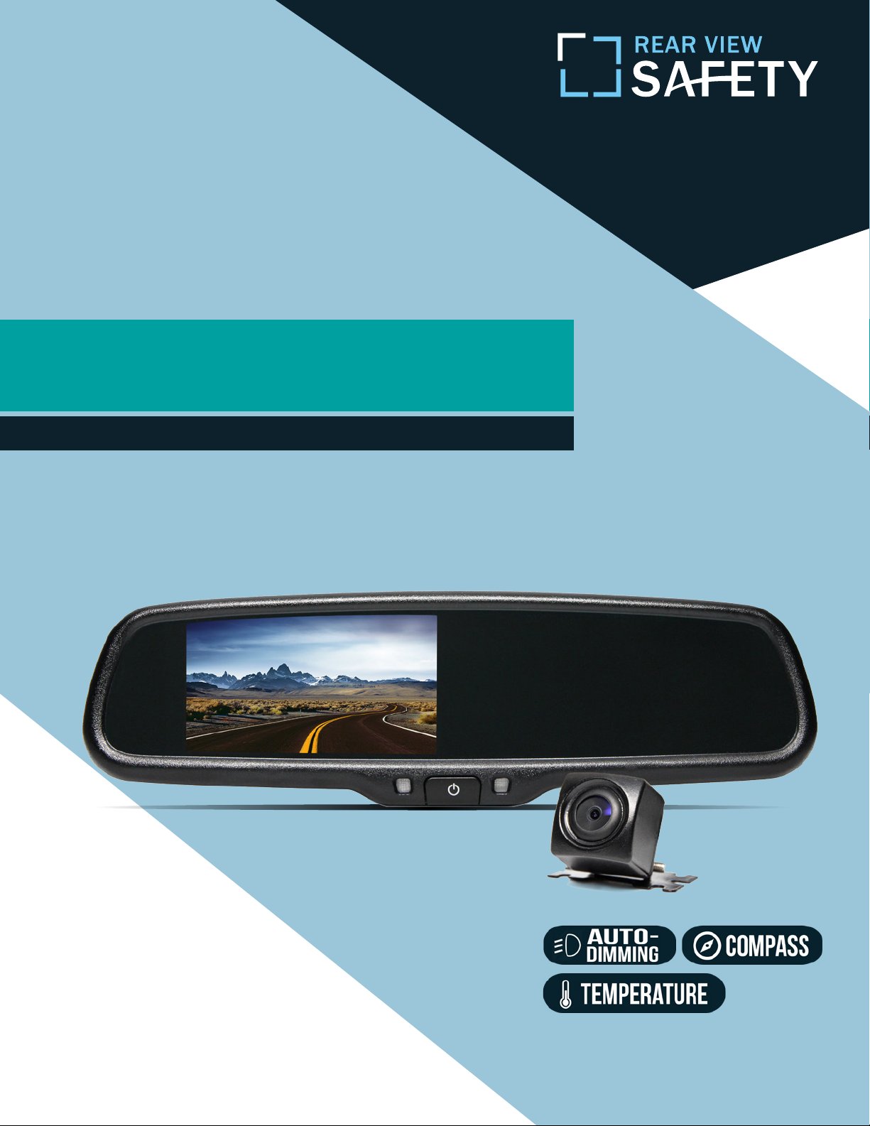
G-SERIES Backup Camera System with
Auto Dimming, Compass and Temperature
RVS-776718-DCT
A Safe Fleet Brand
Reverse With Condence ™
Rear View Safety, Inc. © 2017
1
Page 2
Introduction...............................03
Safety Information..........................04-06
Before Beginning Installation . . . . . . . . . . . . . . . . . . . . . . . 07
Installation Guide.......................... 08-09
Adjustable Grid Line...........................10
Installation and Wire.........................11-13
Digital Compass Calibration......................14-15
TABLE OF CONTENTS
2
Temperature Setting...........................16
Magnetic Fluxline Distribution. . . . . . . . . . . . . . . . . . . 17-19
Monitor Specications .........................20
Camera Specication . .........................21
Camera Installation...........................22
Troubleshooting.............................23
Warranty & Disclaimer........................ 24-25
Rear View Safety
Page 3

NOTE!
Please read all of the installation instructions
carefully before installing the product. Improper
installation will void manufacturer’s warranty.
Congratulations on purchasing a Rear View Backup
Camera System!
With this manual you will be able to properly install and
operate the unit.
The Backup Camera System is intended to be installed as a
supplement aid to your standard rear view mirror that already exists
in your vehicle. The Backup Camera System should not be used as a
substitute for the standard rear view mirror or for any other mirror
that exists in your vehicle.
In some jurisdictions, it is unlawful for a person to drive a
motor vehicle equipped with a TV viewer or screen located forward of
the back of the driver’s seat or in any location that is visible, directly
or indirectly, to the driver while operating the vehicle.
INTRODUCTION
Reverse With Condence ™
3
Page 4

Please read the entire manual and follow the instructions and
warnings carefully. Failure to do so can cause serious damage and/or
injury, including loss of life. Be sure to obey all applicable local
trac and motor vehicle regulations as it pertains to this product.
Improper installation will void manufacturer’s warranty.
USAGE:
• The Rear View Camera System is
designed to help the driver safely detect people and/or objects
helping to avoid damage or injury.
However, you the driver, must use it
properly. Use of this system is not a
substitute for safe, proper or legal
driving.
• Never back up while looking at the
monitor alone. You should always
damage or injury. Always back up
slowly.
• The Rear View Camera System is
not intended for use during extensive back-up maneuvers or backing
into cross trac or pedestrian walkways.
•Please, always remember, the area
displayed by the Rear View Camera
check behind and around the vehi-
SAFETY INFORMATION
cle when backing up, in the same
way as you would if the vehicle did
not have the Rear View Camera
System. If you back up while looking
only at the monitor, you may cause
4
System is limited. It does not display
the entire panorama that is behind
you.
Rear View Safety
Page 5

INSTALLATION:
• Electric shock or product
malfunction may occur if this
product is installed
incorrectly.
• Use this product within
the voltage range specied. Failure
to do so can cause
electronic shock or product
malfunction.
or disconnected wire may cause a
re.
• While installing the Rear View
System be careful with the wire
positioning in order to avoid wire
damage.
• The Rear View System should only
be used when the vehicle is in
reverse.
SAFETY INFORMATION
• Take special care when
cleaning the monitor.
• Make sure to rmly ax the prod-
uct before use.
• If smoke or a burning smell
is detected, disconnect the
system immediately.
• Where the power cable may touch
• Do not watch movies or
operate the monitor while driving;
as it may cause an
accident.
• Do not install the monitor
where it may obstruct drivers
view or obstruct an air bag
device.
a metal case, cover the cable with
friction tape. A short circuit
Reverse With Condence ™
• Dropping the unit may cause
possible mechanical failure.
5
Page 6
If you have questions about this product, contact:
Rear View Safety
1797 Atlantic Avenue
Brooklyn, NY 11233
Tel: 1.800.764.1028
IN NO EVENT SHALL SELLER OR MANUFACTURER BE
SAFETY INFORMATION
LIABLE FOR ANY DIRECT OR CONSEQUENTIAL DAMAGES OF
ANY NATURE, OR LOSSES OR EXPENSES RESULTING FROM
ANY DEFECTIVE PRODUCT OR THE USE OF ANY PRODUCT.
6
A Safe Fleet Brand
Rear View Safety
Page 7

Before drilling please check that no cable or wiring is on the other side
of the wall. Please clamp all wires securely to reduce the possibility
of them being damaged while vehicle is in use. Keep all cables away
from hot or moving parts and electrical noisy components.
We recommend doing a benchmark test before installation
to insure that all components are working properly.
Step 1: Choose the monitor and camera locations.
Step 2: Install all cables in vehicle, when necessary a 0.8 (20mm)
hole should be drilled for passing camera cable through vehicles
walls. Install split grommets where applicable.
Step 3: Once all cables and wiring have been properly routed, perform
a system function test by temporarily connecting the system. If the
system seems to not be operating properly see troubleshooting (page
23).
BEFORE YOU BEGIN
Reverse With Condence ™
7
Page 8

Replacement Monitor
The mirror monitor replaces the existing car mirror. Carefully remove
the mirror o the “pin”. Slide the replacement mirror on to the pin and
secure it with the screw provided (already in the screw hole).Dierent cars have dierent brackets, depending on your vehicle make and
manufacturer. There are many methods to remove the original rearview mirror, however, please don’t force the mirror o the bracket.
The manufacturer will not be responsible for damage caused to your
car by wrong installation of the mirror. Figure 1.1
Clip-On Monitor
1. The Mirror Monitor attaches to the existing rear view mirror in
vehicle with the pressurized clips on the back of the monitor.
2. Attach monitor to existing mirror, and adjust mounting angle to
allow optimum driver viewing comfort.
Camera & Cable
Be sure to position the cable properly. The aviation camera cable uses
INSTALLATION GUIDE
aircraft grade connectors which means the camera cable can be exposed to all weather elements. Do not run the cable over sharp edges,
do not kink the cable and keep away from HOT and rotating parts.
Fasten all cables and secure all excess cable. Connect camera to the
8
camera extension cable which runs inside the vehicle. Figure 1.2
Rear View Safety
Page 9

Wiring
After connecting the camera to the “camera cable” the camera should
be plugged into AV2 input. Connect the RED 12V power wire to an ignition power source and the BLACK 12V ground wire to a chassis ground.
The GREEN wire is the REVERSE trigger wire. Connect this wire to the
vehicle’s backup light circuit to activate the rear-view image whenever
the vehicle shifts into reverse. To connect a second camera, connect it
to AV1 input. It can be turned on by pressing the power button on the
monitor. Figure 2.1, Figure 2.2
Precautions for use of Mirror Monitor
I. The Mirror Monitor is made of glass. Do not subject it to a
mechanical shock by dropping it from a high place, etc.
II. Do not apply excessive force to the monitor surface or the
adjoining areas since this may cause the color tone to vary.
III. Clean with a soft dry cloth and/or Windex only.
IV. Do not attempt to disassemble the mirror monitor.
INSTALLATION GUIDE + TIPS
Safety
• Before drilling, be sure no cable or wire is on the other side.
• Feed as much cable as possible into vehicle & clamp securely.
This reduces the possibility of cable being hooked or snagged.
Reverse With Condence ™
9
Page 10

Grid Lines
Generally, to help drivers estimate the distance from obstacles, there are
three lines for reference- red, yellow, and green. Those three lines are displayed on the monitor when car is reversing. The green line is 3M from the
back of the car and the yellow line is 6.5 ft. The distant red line is 1M from
the backside of car while the close red line is 0.4M. Both reference lines on
the left and right should leave 0.2M space from the car.
Accuracy
ADJUSTABLE GRID LINE
The accuracy of the grid-lines can vary based on how you angle your camera. Therefore to compensate for inaccurancies, you can adjust the gridlines to your camera angle.
10
Rear View Safety
Page 11

FIGURE 1.1
FIGURE 1.2
INSTALLATION AND WIRE
Reverse With Condence ™
11
Page 12

FIGURE 2.1
1. RED- Power (+)
2. YELLOW- Video
HOW TO WIRE + SPLICING
3. GREEN- Mirror / Normal Imaging
4. WHITE- Audio
5. BLACK- Ground (-)
12
Rear View Safety
Page 13

FIGURE 2.2
HOW TO WIRE + SPLICING
Reverse With Condence ™
13
Page 14

Digital Compass Calibration
The compass can be calibrated by driving your vehicle in several complete circles. See
gures below. If the vehicle’s compass headings become inaccurate, the compass
can also be manually calibrated:
1.Press the “MENU” three times to enter into the “SETTING” menu, and press “SEL/REC” to
choose “ANGLE”. Scroll UP/DOWN to adjust the angle.
Please visit: http://magnetic-declination.com/ to nd out the compass angle
of your area. (5-1)
2. Use ”SEL/REC” to select “CALIBRATION”, the default mode is “OFF”, press “DOWN” and
select “AUTO” (1-2)
DIGITAL COMPASS CALIBRATION
3. Drive your vehicle in at least 2 circles counterclockwise, allowing 90 seconds
to complete one circle.
4. Keep your circle radius close to 5 meters and your speed less
than 10km/h for the most accurate calibration. (1-3)
14
Rear View Safety
Page 15

5. Use “SEL/REC” to select “CALIBRATION”, use UP/DOWN to select “OFF” (1-4)
DIGITAL COMPASS CALIBRATION
Caution
1. Make sure the rear view mirror is clearly visable to the driver before calibration.
2. Do not calibrate the compass near a large truck.
3. Make sure that you drive in several complete circles, the steering wheel needs to reach a certain angle for calibration to function properly. The diameter of the driving circle should be close
to 5 meters.
4. Do not drive too fast when calibrating, your pace should be equal to one third normal adult
walking speed. Complete 2-3 circles to nish the calibration.
5. After a new car audio system is installed, the compass needs to be recalibrated. This is because the car’s magnetic eld has changed.
Reverse With Condence ™
15
Page 16

Q&A
Q: Why does the compass need to be calibrated?
A: The magnetism of a car is stronger than the magnetism of the Earth. The compass will only
function properly if it is calibrated to the magnetic conditions of Earth.
Q: Why is the compass not accurate in some areas?
A: In some areas, such as iron mines, high-intensity magnetic elds change the Earth’s
magnetism.
Q: Why are old cars more dicult to calibrate than new cars?
A: The older a car is, the more magnetized it will be. More magnetized cars are more dicult
to calibrate and may still have problems after calibration.
Press “MENU” to enter into “SETTING” menu, and press “SEL/REC” button to choose “TEMP
UNIT”. Toggle UP/DOWN to switch between °F and °C. (4-1)
TEMPERATURE SETTING
Temperature Setting (Option)
16
Rear View Safety
Page 17

Temperature Sensor Installation
Locate the temperature sensor between the front of the radiator and the front
bumper. Slide the metal clip over the edge of the sheet metal or plasic shield until it is secure.
Do not install the temperature sensor near the engine.
MAGNETIC FLUXLINE DISTRIBUTION
The Distribution Of Magnetic Fluxline
We do not recommend using the compass in an area with high magnetic
lines of ux. For example, in the north of Canada.
Reverse With Condence ™
17
Page 18

MAGNETIC FLUXLINE DISTRIBUTION
18
Rear View Safety
Page 19

MAGNETIC FLUXLINE DISTRIBUTION
Reverse With Condence ™
19
Page 20

3”
About Our Monitor
10.25”
SPECIFICATIONS:
Screen Size:
Display Screen:
Display Resolution:
Aspect Ratio:
Color Depth:
Pixel Pitch (mm)
Power Consumption:
MONITOR SPECIFICATIONS
Working Voltage:
Video Input:
4.3”
TFT-LCD
400(H)x234(V)
16:9
16.7M dithering
0.219x0.219
8W
DC 9V-32V
VIDEO-IN to GPS/DVD
(Default) Camera to backup camera
20
Signal System:
PAL/Auto/NTSC
Rear View Safety
Page 21

About Camera
CAMERA SPECIFICATIONS
SPECIFICATIONS:
Reverse With Condence ™
21
Page 22

Camera Installation
170
º
installation
Mounting Position
CAMERA INSTALLATION
view angle
position
22
Rear View Safety
Page 23

No Image On Screen
• Do a hard reset, unplug all cables
and power cables, leave out for 1
minute and then re-connect them
• Check to ensure that the
connection to the camera is tight
• Verify camera cable is plugged into
port labeled Backup Camera
• Verify that the green positive
trigger on power harness is put to
• Verify camera is on correct camera
input
• Verify cable is connected to
monitor
• Verify camera is connected to
cable
• Connect known working camera
and cable to monitor
TROUBLESHOOTING
power 12v+
• Verify Green trigger is receiving
power
Reverse With Condence ™
23
Page 24

ONE YEAR WARRANTY
REAR VIEW SAFETY, INC. WARRANTS THIS PRODUCT AGAINST MATERIAL DEFECTS FOR A
PERIOD OF ONE YEAR FROM DATE OF PURCHASE. WE RESERVE THE RIGHT TO REPAIR OR
REPLACE ANY SUCH DEFECTIVE UNIT AT OUR SOLE DISCRETION. REAR VIEW SAFETY, INC.
IS NOT RESPONSIBLE FOR A DEFECT IN THE SYSTEM AS A RESULT OF MISUSE, IMPROPER
INSTALLATION, DAMAGE OR MISHANDLING OF THE ELECTRONIC COMPONENTS. REAR VIEW
SAFETY, INC. IS NOT RESPONSIBLE FOR CONSEQUENTIAL DAMAGES OF ANY KIND.
THIS WARRANTY IS VOID IF: DEFECTS IN MATERIALS OR WORKMANSHIP OR DAMAGES
RESULT FROM REPAIRS OR ALTERATIONS WHICH HAVE BEEN MADE OR ATTEMPTED BY
OTHERS OR THE UNAUTHORIZED USE OF NONCONFORMING PARTS; THE DAMAGE IS DUE
TO NORMAL WEAR AND TEAR, THIS DAMAGE IS DUE TO ABUSE, IMPROPER MAINTENANCE,
NEGLECT OR ACCIDENT; OR THE DAMAGE IS DUE TO USE OF THE REAR VIEW SAFETY, INC.
SYSTEM AFTER PARTIAL FAILURE OR USE WITH IMPROPER ACCESSORIES.
WARRANTY
WARRANTY PERFORMANCE
DURING THE ABOVE WARRANTY PERIOD, SHOULD YOUR REAR VIEW SAFETY PRODUCT
EXHIBIT A DEFECT IN MATERIAL OR WORKMANSHIP, SUCH DEFECT WILL BE REPAIRED WHEN
THE COMPLETE REAR VIEW SAFETY, INC. PRODUCT IS RETURNED, POSTAGE PREPAID AND
INSURED, TO REAR VIEW SAFETY, INC. OTHER THAN THE POSTAGE AND INSURANCE
REQUIREMENT, NO CHARGE WILL BE MADE FOR REPAIRS COVERED BY THIS WARRANTY.
WARRANTY DISCLAIMERS
NO WARRANTY, ORAL OR WRITTEN, EXPRESSED OR IMPLIED, OTHER THE ABOVE WARRANTY
IS MADE WITH REGARD TO THIS REAR VIEW SAFETY, INC. REAR VIEW SAFETY, INC. DISCLAIMS
ANY IMPLIED WARRANTY OR MERCHANTABILITY OR FITNESS FOR A PARTICULAR USE OR
PURPOSE AND ALL OTHER WARRANTIES IN NO EVENT SHALL REAR VIEW SAFETY. INC.
LIABLE FOR ANY INCIDENTAL, SPECIAL, CONSEQUENTIAL, OR PUNITIVE DAMAGES OR FOR
ANY COSTS, ATTORNEY FEES, EXPENSES, LOSSES OR DELAYS ALLEGED TO BE AS A
CONSEQUENCE OF ANY DAMAGE TO, FAILURE OF, OR DEFECT IN ANY PRODUCT INCLUDING,
BUT NOT LIMITED TO, ANY CLAIMS FOR LOSS OF PROFITS.
24
Rear View Safety
Page 25

DISCLAIMER
REAR VIEW SAFETY AND/OR ITS AFFILIATES DOES NOT GUARANTEE OR PROMISE THAT THE
USER OF OUR SYSTEMS WILL NOT BE IN/PART OF AN ACCIDENT OR OTHERWISE NOT COLLIDE
WITH AN OBJECT AND/OR PERSON. OUR SYSTEMS ARE NOT A SUBSTITUTE FOR CAREFUL
AND CAUTIOUS DRIVING OR FOR THE CONSISTENT ADHERENCE TO ALL APPLICABLE TRAFFIC
LAWS AND MOTOR VEHICLE SAFETY REGULATIONS. THE REAR VIEW SAFETY PRODUCTS ARE
NOT A SUBSTITUTE FOR REARVIEW MIRRORS OR FOR ANY OTHER MOTOR VEHICLE
EQUIPMENT MANDATED BY LAW. OUR CAMERA SYSTEMS HAVE A LIMITED FIELD OF VISION
AND DO NOT PROVIDE A COMPREHENSIVE VIEW OF THE REAR OR SIDE AREA OF THE VEHICLE.
ALWAYS MAKE SURE TO LOOK AROUND YOUR VEHICLE AND USE YOUR MIRRORS TO CONFIRM
REARWARD CLEARANCE AND THAT YOUR VEHICLE CAN MANEUVER SAFELY. REAR VIEW
SAFETY AND/OR ITS AFFILIATES SHALL HAVE NO RESPONSIBILITY OR LIABILITY
FOR DAMAGE AND/OR INJURY RESULTING FROM ACCIDENTS OCCURRING WITH VEHICLES
HAVING SOME OF REAR VIEW SAFETY PRODUCTS INSTALLED AND REAR VIEW SAFETY AND/
OR ITS AFFILIATES, THE MANUFACTURER, DISTRIBUTOR AND SELLER SHALL NOT BE LIABLE
FOR ANY INJURY, LOSS OR DAMAGE, INCIDENTAL OR CONSEQUENTIAL, ARISING OUT OF THE
USE OR INTENDED USE OF THE PRODUCT. IN NO EVENT SHALL REAR VIEW SAFETY AND/OR
ITS AFFILIATES HAVE ANY LIABILITY FOR ANY LOSSES WHETHER DIRECT OR INDIRECT, IN
CONTRACT, TORT OR OTHERWISE INCURRED IN CONNECTION WITH THE SYSTEMS,
INCLUDING BUT NOT LIMITED TO DAMAGED PROPERTY, PERSONAL INJURY AND/OR LOSS OF
LIFE. NEITHER SHALL REAR VIEW SAFETY AND/OR ITS AFFILIATES HAVE ANY
RESPONSIBILITY FOR ANY DECISION, ACTION OR INACTION TAKEN BY ANY PERSON IN
RELIANCE ON REAR VIEW SAFETY SYSTEMS, OR FOR ANY DELAYS, INACCURACIES AND/OR
ERRORS IN CONNECTION WITH OUR SYSTEMS FUNCTIONS.
DISCLAIMER
Reverse With Condence ™
25
Page 26

A Safe Fleet Brand
If you have any questions
about this product, contact:
Rear View Safety, Inc.
1797 Atlantic Avenue
Brooklyn, NY 11233
800.764.1028
Better Cameras. Better Service.
IT’S OUR GUARANTEE.
26
Rear View Safety
 Loading...