

Page 1
Instruction Manual
Advanced Blind Spot Sensor System
RVS-128
VEHICLE SAFETY IT'S ALL WE DO.
TM
Page 2
Item List....................................02
Technical Specication..............................03
Wiring Diagram...............................03-04
Technical Specication
Operating frequency
TECHNICAL SPECIFICATION
24.0 ----24.25GHZ
TABLE OF CONTENTS
Wire Connection Diagram.......................... . 04
Installation Guide. . ............................05-07
Alert Conditions.................................07
Alert Characteristics. . . . . . . . . . . . . . . . . . . . . . . . . . . . . . 08
Troubleshooting . . . . . . . . . . . . . . . . . . . . . . . . . . . 09
Safety Information. . . . . ................... . . . . . 09
Warranty........................... . . . . . 10
Disclaimer........................... . . . . . 11
The RVS Dierence . . . . . .................... . . . . . 12
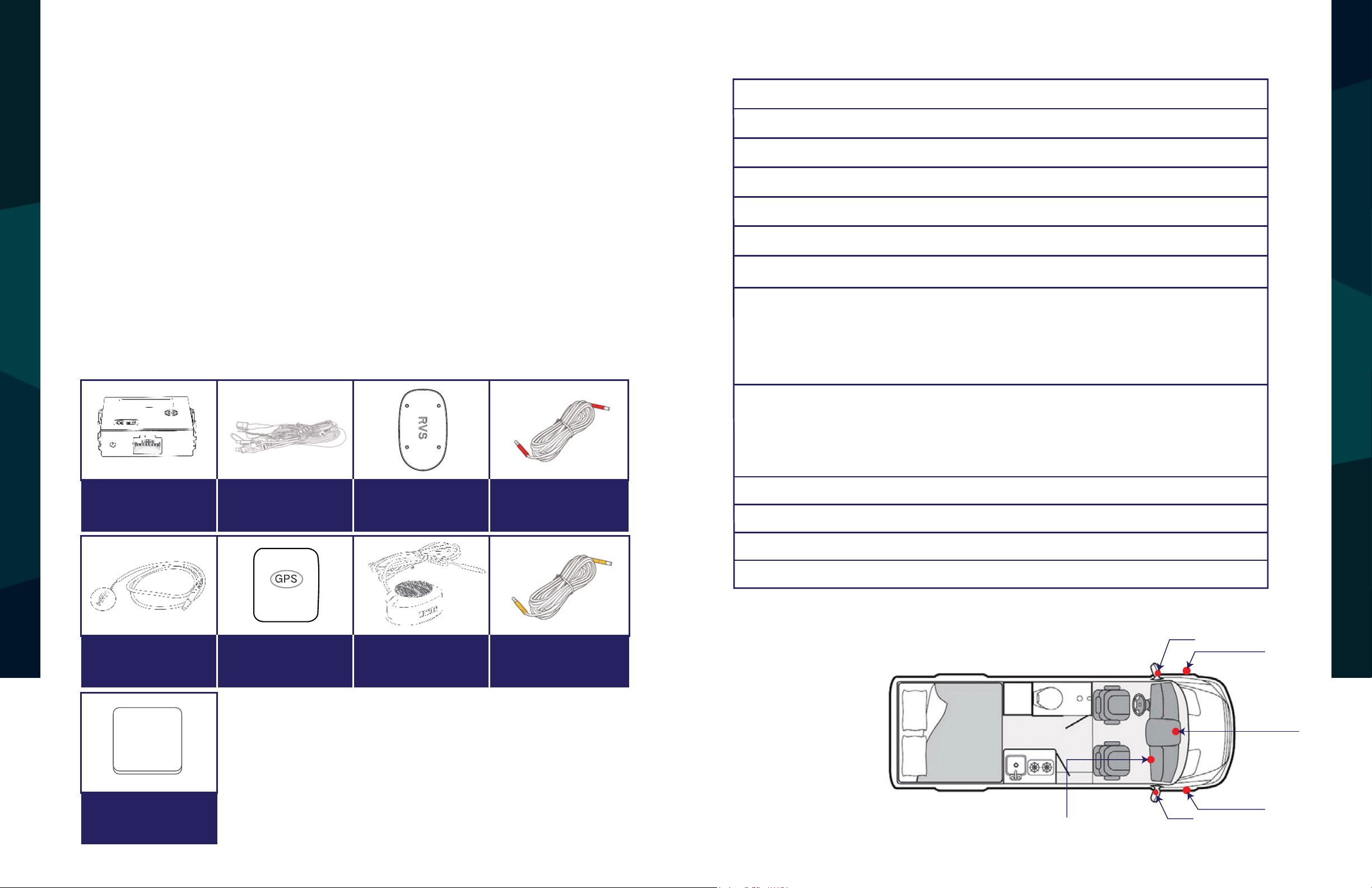
Item List
Transmit power
Detection range
Detection ability
Speed range 0.35mph---137mph
Speed accuracy < 0.35mph
Direction of movement
Speed Restriction
Detection range
15dbm
40 degree (Horizontal )
5 targets can be detected at the same time
Approached or overtaken by vehicles
1.The GPS Antenna when connected activat
notications over 20mph (Example LED + Speaker)
2.If No GPS signal is detected or satellites not found
the sy
Truck : 1ft-82ft
Car: 1ft-50ft
Motorcycle:1ft-33ft
stem will give notications at any speed.
es
,
Main Unit
1PCS
LED Indicator
2PCS
Main Harness
1PCS
GPS Antenna
1PCS
Radar Sensor
2PCS
Buzzer
1PCS
Sensor Extension Cable
2PCS
LED Extension Cable
3PCS
Tools for installation: insulation tape,
multi-meter, screwdriver, cleaning cloth, tape.
Operating voltage
cables waterproof
Working current
Working temperature
Wiring Diagram
Pedestrian:1ft-23ft
9---35V
Radars: IP 67 / Cables: waterproof
< 200mA
-40℃ ~ + 85℃
LED
L-SENSOR
Buzzer
3M Velcro
4PCS
2 3
Rear View Safety Reverse With Condence ™
M ain Unit
LED
R-SENSOR
Page 3
M ain Unit
L-SENSOR
L-SENSOR
R-SENSOR
LED
LED
Buzzer
LED
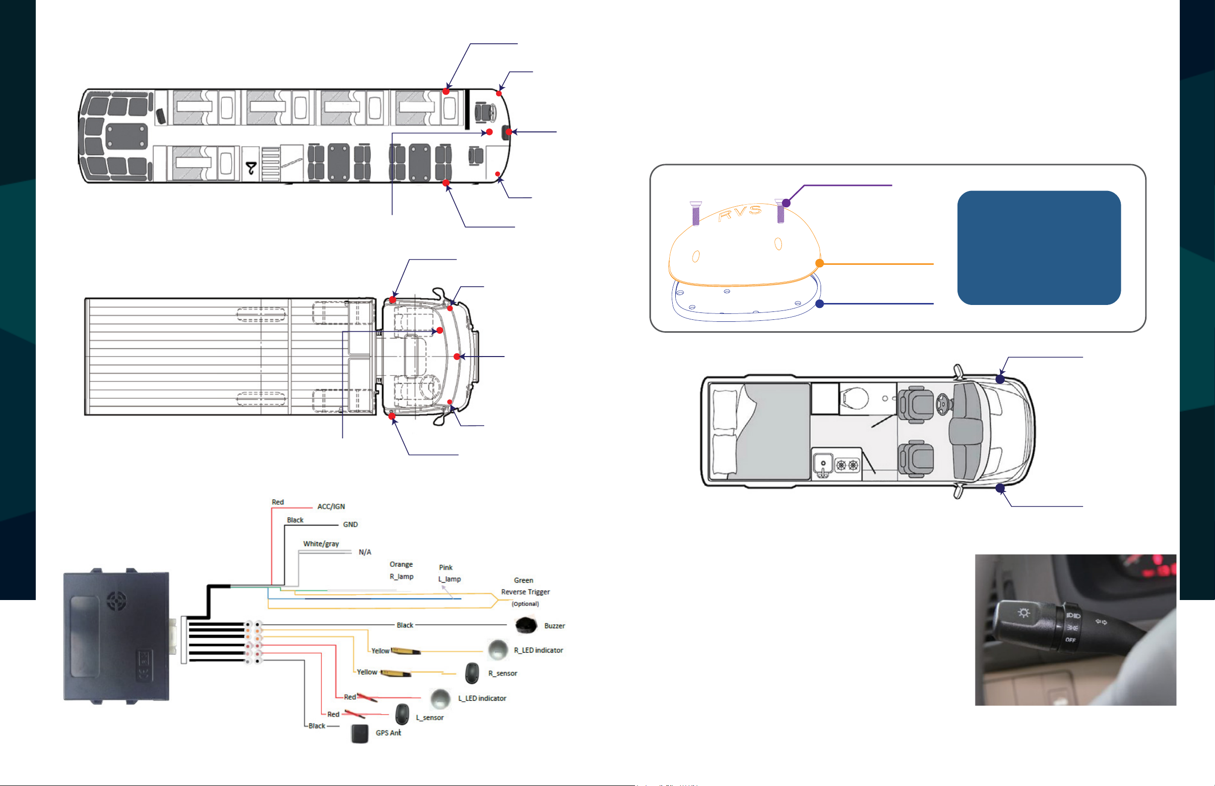
Installation Guide
Step 1. Sensor Installation
Installation requirements: sensors should be mounted to the front corner of the
vehicle, Using screws to x the sensor on the front of the vehicle.
SCREW
Please note.
Letters R and L on the rub-
SENSOR HOUSING
RUBBER GASKET
ber gasket, stands for right
sensor and left sensor.
INSTALLATION GUIDE
WIRE CONNECTION DIAGRAM
Wire Connection Diagram
M ain Unit
L - Left Sensor
Buzzer
LED
R-SENSOR
R - Right Sensor
Step 2. Installation of the left/right turn signal
Using the voltage Multi-meter, locate the left
and right turn signal trigger wires behind the
tail lamp. Once veried, connect the left and
right signal wires of the RVS-128 wire harness
to the correct signal wires.
4 5
Rear View Safety Reverse With Condence ™
Page 4

Step 3. LED Indicator Installation
ALERT CONDITIONS
NOTE!
Place the LED indicators where it is visible for the driver. Ideally on the A-pillar
or in eld view side mirrors.
L - Left LED R - Right LED
INSTALLATION GUIDE
Step 4. Buzzer Location
Illumination of the LED indicator on the control box:
1.The LED comes on solid when the system is rst powered up;
2.The LED blinks slowly while the GPS module is connected to the satellite;
3.The LED blinks quickly while sensing moving objects approaching in the blind spot
(same frequency as to the alarm LED indicators & the buzzer);
4.The LED maintains the last blinking status after the alerts have ended
(the last blinking status of alarming is o / on randomly)
Step 6. Man Box Location
While installing the main box, use tape to mount it on the cab
While installing the speaker, make sure it is not obstructed by any panels inside
the vehicle.
Buzzer
Alert Conditions
1. When the vehicle is on, the system
would start detecting objects in the
blind spot area in the lane next to
and behind the vehicle, up to 82
feet.
2. When vehicles are approaching
Step 5. Tuck the wires neatly to hide and prevent wire pinch.
and their speed is faster than our
own speed.
6 7
Rear View Safety Reverse With Condence ™
Page 5

Alert Characteristics Troubleshooting
Issue Reason
Solution
LED light does not
work
Opposite LED
indicator
Buzzer does not work
Unit does not work
after GPS is connected
Sensors or GPS does
not work
Incorrect connection or pins not
making contact
LED light is broken
Microwave sensor or LED
indicators are plugged in to the
opposite connector
Defective buzzer speaker
Sensors or GPS module are
covered by the metal bumper or
other metal
Sensors or GPS module are
covered by the metal bumper or
other metal
Blind spot system does not
trigger the sensors if the speed is
less than 20mph
Find the best location where the
GPS antenna cannot be blocked
by any metal
Replace buzzer
Wrong connection or pins not
making contact
Check the harness and make sure
connection is correct
Make sure RED is driver side and
YELLOW is passenger side.
Replace LED light
Check the harness and make sure
connection is correct
A. Blind detection on right side:
1. R-LED indicator will be activated when there is an object approaching to the
right side blind area of your vehicle (see Fig.16).
2. If the right turn signal of your vehicle is triggered at the same time, the R-LED
indicator will be blinking and the buzzer will be beeping as well (with the same
frequency).
INSTALLATION GUIDE
B. Blind detection on left side:
1. L-LED indicator will be activated when there is an object approaching to the
TROUBLESHOOTING
left side blind area of your vehicle (see Fig.16).
2. If the left turn signal of your vehicle is triggered at the same time, the L-LED
indicator will be blinking and the buzzer will be beeping as well (with the same
frequency).
C. The LED and buzzer will standby (no activity) if there is no object approaching
to the blind area of your vehicle.
D. During reversing, the R & L LED will be blinking according to the approaching
object detection of each side.
8 9
Rear View Safety Reverse With Condence ™
Page 6

WARRANTY
SAFETY INFORMATION
If you have questions about this product, contact:
Rear View Safety
1797 Atlantic Avenue
Brooklyn, NY 11233
Tel: 1.800.764.1028
IN NO EVENT SHALL SELLER OR MANUFACTURER BE
ONE YEAR WARRANTY
REAR VIEW SAFETY, INC. WARRANTS THIS PRODUCT AGAINST MATERIAL DEFECTS FOR A
PERIOD OF ONE YEAR FROM DATE OF PURCHASE. WE RESERVE THE RIGHT TO REPAIR OR
REPLACE ANY SUCH DEFECTIVE UNIT AT OUR SOLE DISCRETION. REAR VIEW SAFETY, INC.
IS NOT RESPONSIBLE FOR A DEFECT IN THE SYSTEM AS A RESULT OF MISUSE, IMPROPER
INSTALLATION, DAMAGE OR MISHANDLING OF THE ELECTRONIC COMPONENTS. REAR VIEW
SAFETY, INC. IS NOT RESPONSIBLE FOR CONSEQUENTIAL DAMAGES OF ANY KIND.
THIS WARRANTY IS VOID IF: DEFECTS IN MATERIALS OR WORKMANSHIP OR DAMAGES
RESULT FROM REPAIRS OR ALTERATIONS WHICH HAVE BEEN MADE OR ATTEMPTED BY
OTHERS OR THE UNAUTHORIZED USE OF NONCONFORMING PARTS; THE DAMAGE IS DUE
TO NORMAL WEAR AND TEAR, THIS DAMAGE IS DUE TO ABUSE, IMPROPER MAINTENANCE,
NEGLECT OR ACCIDENT; OR THE DAMAGE IS DUE TO USE OF THE REAR VIEW SAFETY, INC.
SYSTEM AFTER PARTIAL FAILURE OR USE WITH IMPROPER ACCESSORIES.
LIABLE FOR ANY DIRECT OR CONSEQUENTIAL DAMAGES OF
ANY NATURE, OR LOSSES OR EXPENSES RESULTING FROM
ANY DEFECTIVE PRODUCT OR THE USE OF ANY PRODUCT.
Before drilling please check that no cable or wiring is on the other side
of the wall. Please clamp all wires securely to reduce the possibility
of them being damaged while vehicle is in use. Keep all cables away
from hot/moving parts and electrical noisy components.
WARRANTY PERFORMANCE
DURING THE ABOVE WARRANTY PERIOD, SHOULD YOUR REAR VIEW SAFETY PRODUCT
EXHIBIT A DEFECT IN MATERIAL OR WORKMANSHIP, SUCH DEFECT WILL BE REPAIRED WHEN
THE COMPLETE REAR VIEW SAFETY, INC. PRODUCT IS RETURNED, POSTAGE PREPAID AND
INSURED, TO REAR VIEW SAFETY, INC. OTHER THAN THE POSTAGE AND INSURANCE
REQUIREMENT, NO CHARGE WILL BE MADE FOR REPAIRS COVERED BY THIS WARRANTY.
WARRANTY DISCLAIMERS
NO WARRANTY, ORAL OR WRITTEN, EXPRESSED OR IMPLIED, OTHER THE ABOVE WARRANTY
IS MADE WITH REGARD TO THIS REAR VIEW SAFETY, INC. REAR VIEW SAFETY, INC. DISCLAIMS
ANY IMPLIED WARRANTY OR MERCHANTABILITY OR FITNESS FOR A PARTICULAR USE OR
PURPOSE AND ALL OTHER WARRANTIES IN NO EVENT SHALL REAR VIEW SAFETY. INC.
LIABLE FOR ANY INCIDENTAL, SPECIAL, CONSEQUENTIAL, OR PUNITIVE DAMAGES OR FOR
ANY COSTS, ATTORNEY FEES, EXPENSES, LOSSES OR DELAYS ALLEGED TO BE AS A
We recommend doing a benchmark test before installation
to ensure that all components are working properly.
10 11
Rear View Safety Reverse With Condence ™
CONSEQUENCE OF ANY DAMAGE TO, FAILURE OF, OR DEFECT IN ANY PRODUCT INCLUDING,
BUT NOT LIMITED TO, ANY CLAIMS FOR LOSS OF PROFITS.
Page 7

THE RVS DIFFERENCE
DISCLAIMER
REAR VIEW SAFETY AND/OR ITS AFFILIATES DOES NOT GUARANTEE OR PROMISE THAT THE
USER OF OUR SYSTEMS WILL NOT BE IN/PART OF AN ACCIDENT OR OTHERWISE NOT COLLIDE
WITH AN OBJECT AND/OR PERSON. OUR SYSTEMS ARE NOT A SUBSTITUTE FOR CAREFUL
AND CAUTIOUS DRIVING OR FOR THE CONSISTENT ADHERENCE TO ALL APPLICABLE TRAFFIC
DISCLAIMER
LAWS AND MOTOR VEHICLE SAFETY REGULATIONS. THE REAR VIEW SAFETY PRODUCTS ARE
NOT A SUBSTITUTE FOR REARVIEW MIRRORS OR FOR ANY OTHER MOTOR VEHICLE
EQUIPMENT MANDATED BY LAW. OUR CAMERA SYSTEMS HAVE A LIMITED FIELD OF VISION
AND DO NOT PROVIDE A COMPREHENSIVE VIEW OF THE REAR OR SIDE AREA OF THE VEHICLE.
ALWAYS MAKE SURE TO LOOK AROUND YOUR VEHICLE AND USE YOUR MIRRORS TO CONFIRM
REARWARD CLEARANCE AND THAT YOUR VEHICLE CAN MANEUVER SAFELY. REAR VIEW
SAFETY AND/OR ITS AFFILIATES SHALL HAVE NO RESPONSIBILITY OR LIABILITY
FOR DAMAGE AND/OR INJURY RESULTING FROM ACCIDENTS OCCURRING WITH VEHICLES
THE RVS DIFFERENCE
COMPETITION
Sensors mounted
in rear corners
THE RVS DIFFERENCE
Our sensors mounted in the
front of the vehicle
82FT
RANGE!
HAVING SOME OF REAR VIEW SAFETY PRODUCTS INSTALLED AND REAR VIEW SAFETY AND/
OR ITS AFFILIATES, THE MANUFACTURER, DISTRIBUTOR AND SELLER SHALL NOT BE LIABLE
FOR ANY INJURY, LOSS OR DAMAGE, INCIDENTAL OR CONSEQUENTIAL, ARISING OUT OF THE
USE OR INTENDED USE OF THE PRODUCT. IN NO EVENT SHALL REAR VIEW SAFETY AND/OR
ITS AFFILIATES HAVE ANY LIABILITY FOR ANY LOSSES WHETHER DIRECT OR INDIRECT, IN
CONTRACT, TORT OR OTHERWISE INCURRED IN CONNECTION WITH THE SYSTEMS,
INCLUDING BUT NOT LIMITED TO DAMAGED PROPERTY, PERSONAL INJURY AND/OR LOSS OF
LIFE. NEITHER SHALL REAR VIEW SAFETY AND/OR ITS AFFILIATES HAVE ANY
RESPONSIBILITY FOR ANY DECISION, ACTION OR INACTION TAKEN BY ANY PERSON IN
RELIANCE ON REAR VIEW SAFETY SYSTEMS, OR FOR ANY DELAYS, INACCURACIES AND/OR
ERRORS IN CONNECTION WITH OUR SYSTEMS FUNCTIONS.
12 13
Rear View Safety Reverse With Condence ™
Page 8

If you have any questions
about this product, contact:
Rear View Safety, Inc.
1797 Atlantic Avenue
Brooklyn, NY 11233
800.764.1028
Better Cameras. Better Service.
IT’S OUR GUARANTEE.
 Loading...