

Page 1
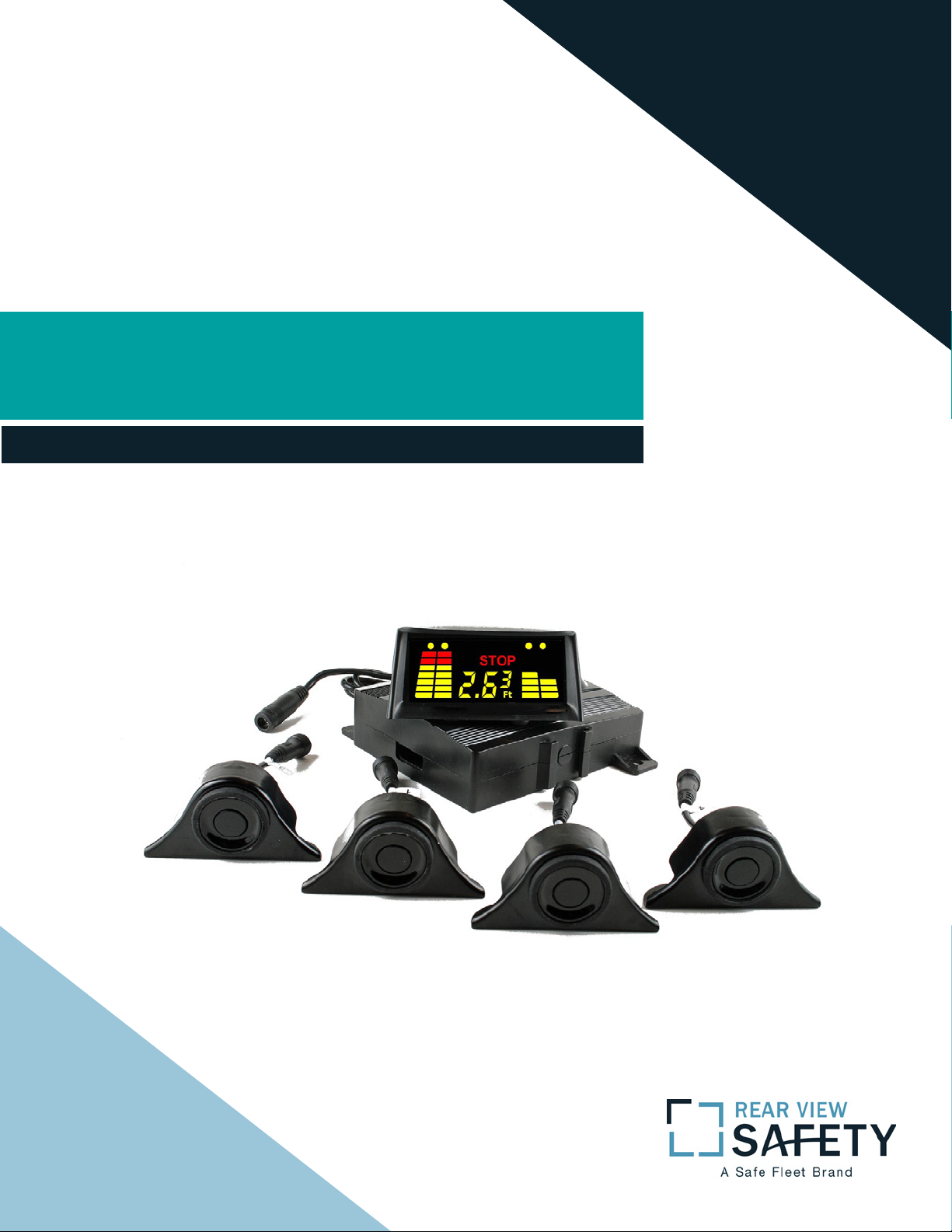
Instruction Manual
Wired and Wireless Obstacle
Detection Sensor Systems
Page 2

Table of Contents
Contact us 3
Product Overview 4
Product Features 4-5
Package Contents (Hardware) 6
About the Monitor 7-8
About the ECU 8-9
About the Sensors 10
Sensor Installation 11
Sensor Installation (In-Bumper Flush Mount) 12-14
TABLE OF CONTENTS
Sensor Installation (SE Version) 15-18
Alternate Sensor Mounting Locations 18-20
ECU Installation Location & Sensor Connection 21-22
ECU Installation (Specic to Wired Systems) 22
ECU Installation (Specic to Wireless Systems on Trailers) 22
Monitor Installation 23
Monitor Function Setup 23-24
Setting Stop-line Adjustment 24
Installation Test (in order shown) 25-26
System Operation 26-27
Warranty 28
Disclaimer 29
2
Rear View Safety
Page 3

If you have questions about this product, contact:
Rear View Safety
1797 Atlantic Avenue
Brooklyn, NY 11233
Tel: 1.800.764.1028
IN NO EVENT SHALL SELLER OR MANUFACTURER BE
LIABLE FOR ANY DIRECT OR CONSEQUENTIAL DAMAGES OF
ANY NATURE, OR LOSSES OR EXPENSES RESULTING FROM
ANY DEFECTIVE PRODUCT OR THE USE OF ANY PRODUCT.
Contact us
Reverse With Condence ™
3
Page 4

Product Overview
SenseStat® is a unique family of Obstacle Detection Sensor Systems
(ODSS) that uti-lize the latest ultrasonic technology to detect objects
that are up to eight (8) feet from the rear of a vehicle. These backup alert, reverse-sensing systems, are available in both wired and
wireless congurations designed for multiple commercial vehicle appli-cations. SenseStat uses a Sensor-scanning algorithm that reads
each of four (4) sepa-rate Sensors providing the ability to Monitor
4-zones across the width of a vehicle. The result is a greater degree
of “blind spot” coverage in helping to prevent backing acci-dents, improper back-ups and allows for convenient tractor/trailer exchange
with all SenseStat equipped trucks.
Product Features
• Automatic activation when in reverse – Drivers don’t have to remember to turn onthe system. It’s there for you every time you put
your vehicle in reverse.
• Easy trailer switch (Wireless Only)– For tractor trailer rigs, just con-
PRODUCT OVERVIEW
nect to anySenseStat-equipped trailer, press the Monitor’s sync button and you’re connected andready to roll.
• Flexible Sensor placement – If overheads or low-hanging wires are
a concern,SenseStat Sensors can be installed at the top corners of
your vehicle: front orback. They can also be split between truck top
and bumpers.
4
Rear View Safety
Page 5

• Virtual bumper – For lift trucks or vehicles with extended bumpers,
SenseStat’s Stop-line Adjustment will adjust your stopping distance
(zero point) away from the actualbumper by whatever distance you
need. This allows for accurate stopping with allow-ance for overhanging ladders, folding lifts or other protrusions.
• Long trailers, extended cabs or busses – By installing the wireless
system, youeliminate the need for long wire runs through sometimes-complex wiring routes.
• SenseStat SE— oers a rugged housing for the systems four Sensors.
These heavy-duty, 2” x 3.2” x 1.4” shock-absorbent housings adapt to a
wide variety of vehiclesrequiring either a vertical or horizontal installation. Protect your systems against roughhandling, roadwear, construction sites and other conditions that might aect your in-vestment in
safety.
Power Input 10.5~24VDC
Power Consumption ECU: 200mA Max, LED Monitor: 250mA Max
Distance Detection 0.72~8.20 (ft) / 0.22~2.5 (M)
Detection Tolerance +/- 0.8 inches / +/- 0.02M (at 25°C )
Operating Temp -30°C to +75°C
Storage Temp -30°C to +80°C
Product Features
Dimensions ECU: 4.33” (L) x 3.62” (W) x 1.25” (H)
Monitor: 2.95”(L) x 3.54” (W) x 1.57” (H)
Weight ECU: 1 lb / .45 kg, Monitor: 22 lb / 1kg
Reverse With Condence ™
5
Page 6

Package Contents (Hardware)
• Monitor
• Wired (P/N: MA-ODSS-4D)
• Wireless (P/N: MA-ODSS-4DWA)
• ECU
• Wired (P/N: MA-ODSS-ECU)
• Wireless (P/N: MA-ODSS-ECUWA)
• Sensor with Rubber Boot (P/N: MA-ODSS-M17S)
• Sensor and Metal Under Bumper Sensor Mounts (P/N: MA-ODSS-M17SM)
• Box Truck Extension Cables - If Purchased as Box Truck Wired System
(P/N: MA-ODSS-4M17-BTC)
• One (2) 10M Extension Cable
• One (1) 1.2M “Y” Power Cable
• Straight Antenna (Mounts directly to ECU) - Wireless Only (P/N: MA-ODSS.SA)
• Straight Antenna with 10’ of Attached Cable - Wireless Only
(P/N: MA-ODSS-EA10)
• Mounting Bracket (P/N: MA-ODSS-EAMB)
Optional Items and Accessories
PACKAGE CONTENTS (HARDWARE)
• 5M Sensor Extension Cable (P/N: MA-ODSS-M17-SCE)
• Both Wired and Wireless Systems
• Connects between ECU and Sensor
• SE Enhanced Sensor Mounts - If Purchased as SE System or can
be added later
• SE Mount with Sensor (P/N: MA-ODSS-M17SE)
• SE Mount only (P/N: MA-ODSS-M17SE-M)
6
Rear View Safety
Page 7
About the Monitor
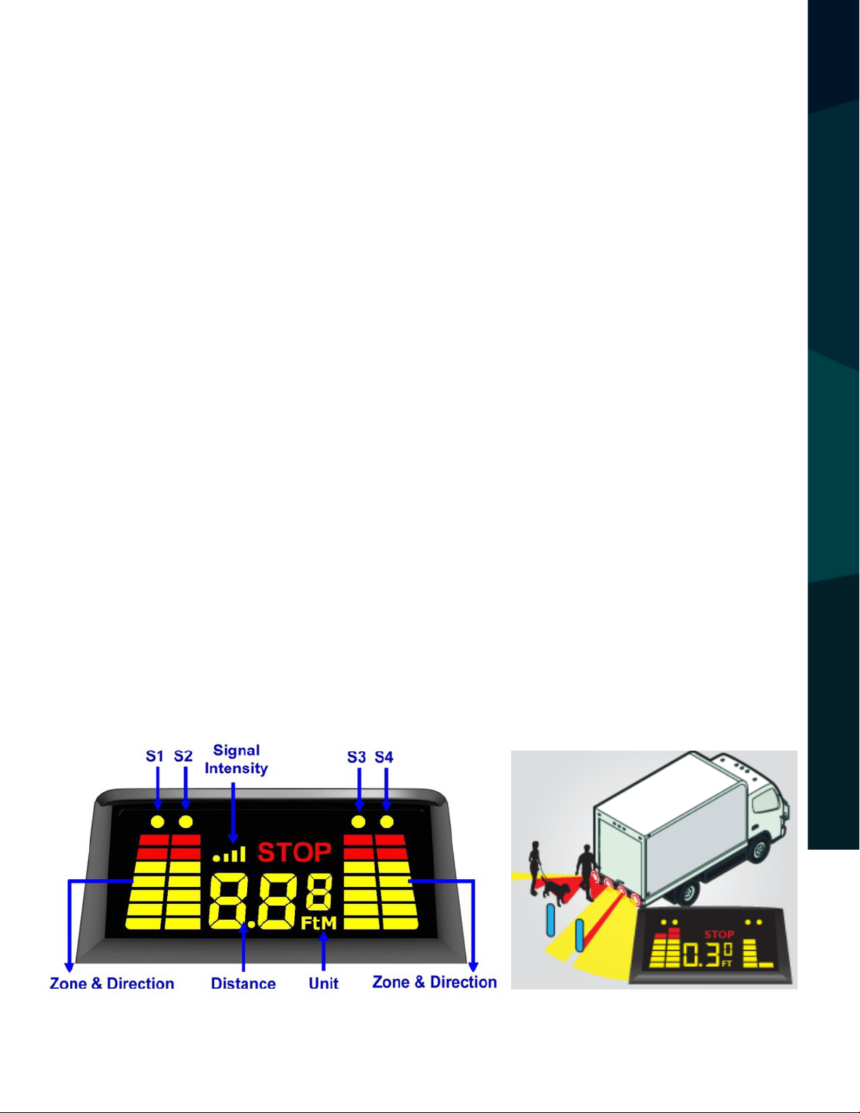
The Monitor consists of a bright LED display having 4 individual bar
(Sensor) indicators and a distance meter. The advanced capabilities
of the system are designed such that the dash-mounted display will
indicate the distance (in feet & inches or meters) of the Sensor that is
closest to an object. The yellow dot at the top of the Sensor (S1, S2, S3
or S4) that is closest to an object will ash while that Sensors distance
to the object is indicated on the display. As the vehicle is moving, if an
object becomes closer to a dierent Sensor, the yellow dot over that
Sensors bar will ash and indicate its distance to the new closest object.
See the table on page 15 for more information on when the Monitor
will provide visual and audible warnings
ABOUT THE MONITOR
Reverse With Condence ™
7
Page 8

About the Monitor
• Indication of Sensors: S1, S2, S3, S4 indicate Sensor locations from left to
right (see Fig 8)
• Indication of Direction and Zone: The 4 LED column bars show the Direction
and Zone (Sensor) of the obstacle
• Indication of Distance: Shows the distance from the Sensor to the obstacle in
meters or in feet & inches of the Sensor that is closest to an object
• Signal Intensity: Shows the wireless signal strength (when applicable).
• Unit: Displays the unit of measurement being used, feet or metersIndication
of Sensors: S1, S2, S3, S4 indicate Sensor locations from left to right (see Fig 8)
• Indication of Direction and Zone: The 4 LED column bars show the Direction
ABOUT THE MONITOR
and Zone (Sensor) of the obstacle
• Indication of Distance: Shows the distance from the Sensor to the obstacle in
meters or in feet & inches of the Sensor that is closest to an object
• Signal Intensity: Shows the wireless signal strength (when applicable).
• Unit: Displays the unit of measurement being used, feet or meters
NOTE: See the table on page 15 for more information on when the Monitor will
provide visual and audible warnings.
About the ECU
The Electronic Control Unit (ECU) is an intelligent microcontroller system with
four (4) individual Sensor inputs, all contained in a waterproof enclosure. There
are four (4) integrated cables labeled S1, S2, S3 and S4, which will connect to
the four (4) each Sensor Units. There are two mounting holes for securing the
ECU at the rear of the vehicle. Since the ECU is watertight, it can be installed
underneath the vehicle to facili-tate the installation. Two antenna options are
8
Rear View Safety
Page 9
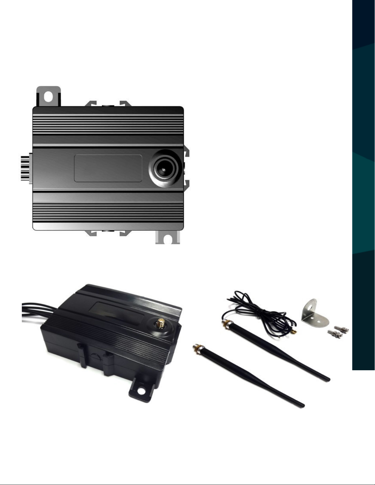
available for the Wireless ECU to assist with the installation depending on
your mounting location and needs pertaining to your vehicle. See the install
section of this manual for further information.
Fig 2: Wired ECU
Fig 3: Wireless ECU Fig 4: Wireless Antennas
ABOUT THE ECU
Reverse With Condence ™
9
Page 10

About the Sensors
The Sensor Unit consists of a waterproof ultrasonic transducer designed for
high accu-racy measurement of up to 8 feet or approximately 2.5 meters. The
standard mount consists of a rubber sleeve, set in a metal mounting bracket
for mounting under the bumper. The Sensors can also be mounted directly
in the bumper using the rubber boot or on the face of the bumper using the
optional SE Sensor Mount (see Fig 14). The Sensors are labeled S1, S2, S3 &
S4 to match the waterproof threaded connect-ors which have an O-ring seal.
Fig 5: Sensor in Metal Bracket Fig 6: Sensor, Rubber Sleeve &
ABOUT THE SENSORS
Fig 7: Waterproof Threaded Sensor Connectors
10
Metal Bracket
Rear View Safety
Page 11

Sensor Installation
1) The width of vehicles vary. It is important to install the Sen-sors at
the appropriate dis-tance and location along the rear bumper or equivalent (see Fig 8). Assuming that the width of vehicle is L, then the space
between Sensors is 1/4L (Sensors must be mounted S1, S2, S3, S4, from
left to right).
• Sensors S1 and S4 should be located approximately 1/8L from either
side of the vehicle. S2 and S3 will be located 1/4L from S1 and S4.
If the Sensors are mounted on a DOT type bumper, the Sensor locations
are deter-mined by the vehicle width (L), not the width of the bumper.
2) Sensors should be mounted at an absolute minimum of 16 inches
SENSOR INSTALLATION
(40cm) to 32 inches (80cm) from the ground (20 inches (50cm) is a
good choice, if available). See Alternate Sensors Mounting Locations,
Fig 22, for other options.
Reverse With Condence ™
11
Page 12

Sensor Installation (In-Bumper Flush Mount)
For vehicles equipped with a bumper that can accommodate the Sensors,
carefully drill a 25mm hole and insert the Rubber Jacket, properly orientated
“UP”, in the hole rst. Then insert the Sensor, again properly orientated “UP”
(see Fig 9). Depending on the thickness and construction of the bumper, the
hole diameter may need to be varied. The Rubber Jacket is designed to seat
properly into a 25mm hole with a 1/8 inch (3.2mm) thick metal bumper. If
this is not the case, the anges on the Rubber Jacket must be taken into consideration. It is suggested that a test hole be utilized to conrm a proper t.
Fig 9: UP
SENSOR INSTALLATION
Sensor Installation (Standard Metal Under Bumper Bracket)
Installing the Under Bumper
• With a drill bit (M5), make 2 holes spaced 2.1875 inches (2 3/16” or
55.6mm) apart in the bumper or equivalent. They should be set back no
more than 0.6 inches (15mm) from the front edge of the bumper. It is recommended to always take your own measurements to ensure proper installa-tion.
12
Rear View Safety
Page 13

• Attach the Sensors on the bumper or simi-lar vehicle xture (metal bar, etc.)
with the enclosed mounting hardware.
• Some bumpers may not be exactly parallel to the ground. When needed, the
Sensor’s vertical angle can be adjusted by placing a shim between the bracket
and bumper.
• See Fig 11, Fig 12 and Fig 13 for addition-al Information on Sensor conguration.
SENSOR INSTALLATION
Fig 10: Under-bumper Assembly & Mount for Standard
Metal Bracket Sensor
Reverse With Condence ™
13
Page 14

Fig 11: Sensor “UP” Indicator Fig 11: Se Fig 12: Rear of Metal
Bracket Assembly (oriented “UP”)
nsor “UP” Indicator
SENSOR INSTALLATION
Fig 12: Rear of Metal
Bracket Assembly
(oriented “UP”)
14
Fig 14: SE Mount
Rear View Safety
Page 15

Sensor Installation (SE Version)
The SE Mount is an enhanced mounting method that further protects the Sensors while providing alternate mounting op-tions. The solid rubber compound
SE Mount is designed to securely and conveniently attach the SenseStat Sensor
to your vehicle. To facilitate the installation, 2 each #6-32 Stain-less Steel Hex
Screws (2 inches in length) are provided, along with the appropriate washers
and hex nuts. To proper-ly ax the SE Mount, use only the hardware provided,
mak-ing sure to use the Flat Washer (0.375 inch outside diame-ter) in the front
of and in back of each unit. If the screw is not long enough, be sure to use #6-32
Stainless Steel Socket Hex Screws only.
1) Begin by examining the rear of the vehicle for the best location to secure the
Sensors. Below, in Fig 15 and Fig 16, are examples of how the SE Mount can be
orient-ed either horizontally or vertically. Depending on any space constraints,
decide which orientation is best suited for your vehicle. If you encounter any
diculty in doing so, please contact RVS Technical Support for assistance. The
formula, Fig 8, will still be followed for spacing of the sensors.
SENSOR INSTALLATION (SE VERSION)
Fig 15: SE Sensor Mounted Horizontally
Reverse With Condence ™
15
Page 16

Fig 16: SE Sensor Mounted Vertically
2) Once the location and orientation are determined, mark and drill the
2 (two) Sensor mount holes (0.156” or 5/32”) to accommodate the #6-32
screws. Refer to Fig 17 for the proper hole spacing which is 2.20” or 56mm
center to center.
3) Before attaching the SE Sensors to the vehicle, the Sensor Element must
be inserted into the center hole by pressing it into the front of the SE Mount. If
the Sen-sor is already inserted into the SE Sensor Mount, it may need to be rotated depending on the orientation. If the Sensor is mounted in the Standard
Metal Bracket remove it carefully pressing the rear of the Sensor for-ward out
of the Rubber Boot.
SENSOR INSTALLATION (SE VERSION)
4) Depending on the orientation of the SE Mount, the Sensor must be positioned (rotated) such that the “UP” Indicator (Fig 11) is pointing upward prior
to mounting to the vehicle. There is a slight angle (approximately 3 degrees)
on the face of the Sensor (indicated by the dotted line in Fig 13). This angle
helps to compensate for weight added to trucks which causes the back end to
lower. As a result, the Sensor may point slightly toward the ground. This could
cause the Sensor to detect reected signals from the ground if the angle was
too extreme.
16
Rear View Safety
Page 17

5) View the backside of the SE Mount prior to attaching to the vehicle to
determine the best way to route the Sensor Element wires. There are three (3)
wire slot guides available as indicated in Fig 19.
Depending on the type of installation, the Sensor Element wires can also
run through a large center hole as long
there is a similar size hole in the
6) Attach the SE Mount with the correctly oriented Sensor to the vehicle with the
enclosed mounting hardware. Make sure
that the face of the Sensor is perpen-dic-
SENSOR INSTALLATION (SE VERSION)
ular to the ground. In situations where the
face of the Sensor is not per-pendicular to
the ground, the Sensor’s vertical angle can
be adjusted by placing a shim between the
SE Mount and the bumper.
7) Make sure the Sensors are securely fastened by tightening the Stainless
Steel Nylon Lock Nuts to prevent the screws from loosening due to vehicle vibration.
Fig 17: SE Mount Drill
Hole Spacing
Fig 18: SE Mount
and Hardware
Reverse With Condence ™
17
Page 18

Fig 19: Backside of SE Sensor Mount
Alternate Sensor Mounting Locations
The system is designed to be installed with
all 4 (four) Sensors aligned across the rear of
the vehicle, preferably at a height ranging
from 16” to 32” from the ground. When the
Sensors are installed in a dierent layout
(for example to detect a building overhang
ALTERNATE SENSOR MOUNTING LOCATIONS
as shown on the right), please consider the
following:
• Each Sensor detects objects in a circular
area approximately 20” in diameter. The
Sensor eld of coverage can be seen below
in Fig 21.
• When the Sensors are placed on two
18
Fig 20
Rear View Safety
Page 19
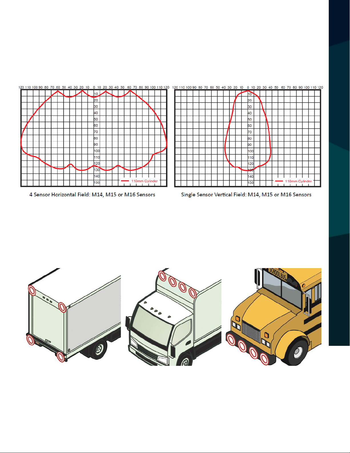
dierent levels (per the example to the right) install S1 and S4 on the top and
S2 and S3 on the bottom of the vehicle.
• It is recommended that the face of all Sensors should be on the same plane to
ensure the accuracy of the system.
CAMERA SPECIFICATIONS
Sensors can also be mounted across the front of the vehicle to detect building
overhangs or to detect objects out of view.
NOTE: SenseStat is a tool to help the driver. The driver should always know
what is in front of or behind them and physically check the area themselves.
Fig 22: Alternate Sensor Mounting Locations
CAUTION: Using less than 4 (four) Sensors across the width of a bumper will create limited coverage resulting in blind zones! It is strongly suggested that these blind zones
are mapped out to educate the driver regarding the system limitations. See Fig 23.
Reverse With Condence ™
19
Page 20
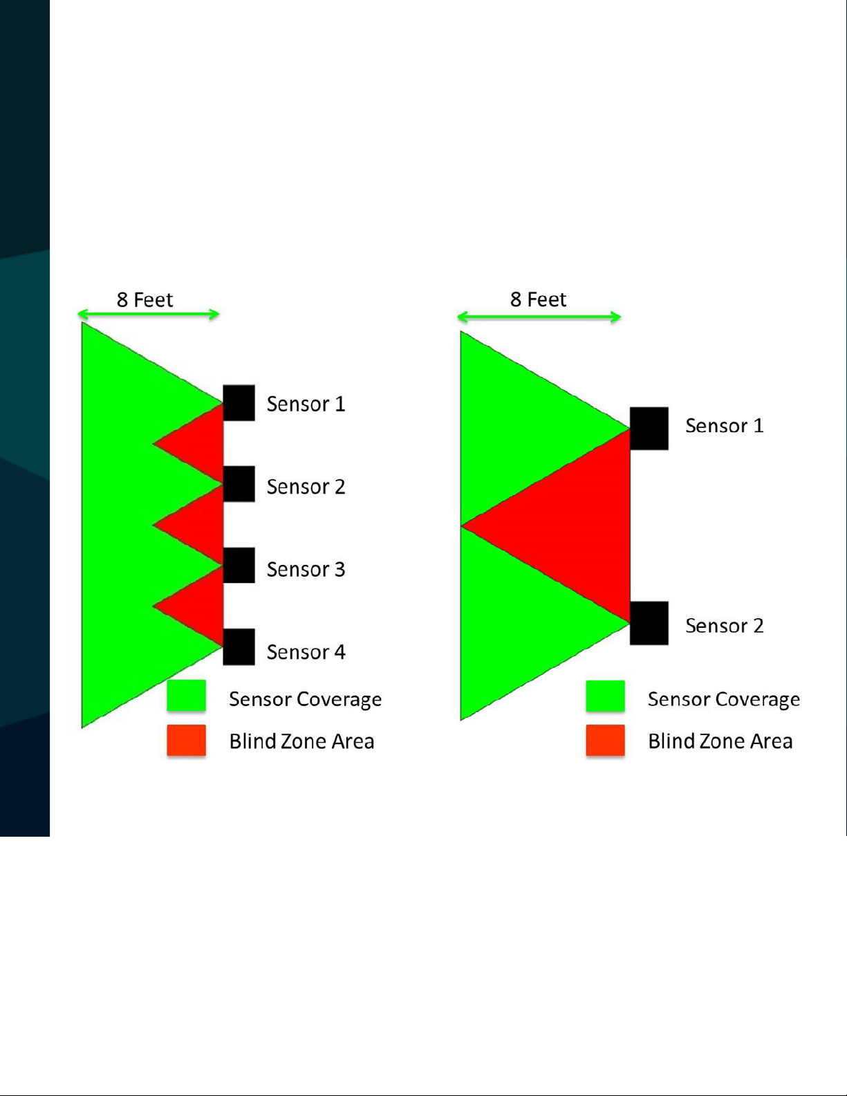
Having all four Sensors in line, on the same plane, provides the best result. If
you break the Sensor con-guration up, for example two on top and two on
bottom, you create a bigger gap between the Sensors, causing a large blind
zone area. This blind zone area can lead to objects or people being undetected by the Sensors.
MONITOR SPECIFICATIONS
Fig 23: Sensor Conguration and Blind Zones
20
Rear View Safety
Page 21

ECU Installation Location & Sensor Connection
1) Depending on the vehicle type, select an appropriate location to mount
the water-tight ECU on the rear undercarriage of the truck chassis (see Fig 24).
Make sure the ECU is installed 4 inches (10cm) away from any objects (metal or electrical) that may aect the wireless
transmission (if applicable).
2) If Wireless, connect either antenna to the ECU. If using the Straight
Antenna, the ECU should be mounted in an open area and free from obstruction. Do not place the ECU in the frame of the vehicle or any enclosed area.
The Straight Antenna will screw onto the ECU and the ECU should be mounted
ECU INSTALLATION LOCATION & SENSOR CONNECTION
so that the antenna is pointing towards the road. If us ing the External Mount
Antenna, the ECU can be mounted in various places, including tucked into
the frame of the vehicle. The External Mount Antenna comes with 10 feet of
attached cable to allow the antenna to be mounted in another location using the included mounting bracket (see Fig 4). Again, this antenna should be
mounted in an open area to ensure proper transmission. It is recommended to
mount the antenna on the same side of the vehicle as the monitor, with the
anten-na pointing to the front of the vehicle.
Fig 25: Mounting
Tabs and Hardware
Fig 24: Mounting the ECU
Reverse With Condence ™
21
Page 22

3) Secure with the two (2) enclosed mounting bolts (M6x10). Be sure to
secure the ECU tightly to prevent the unit from becom-ing loose due to road
vibration. See Fig 25.
4) The ECU provides 12 inches of cable built into the ECU. In order to connect
the Sensors to the ECU, four (4) exten-sion cables have been provided (see
Fig 26). Securely fasten these extension cables to the vehicle using cable
ties, drilling holes, using existing pathways or using the frame of the vehicle.
Securely tighten the watertight extension cables, to both the ECU and the
Sensors, to the same numbered ECU cable connectors labeled S1, S2, S3 &
S4., from left to right.
5) Powering the ECU will vary depending on Wired or Wireless and the
vehicle itself. NOTE: RVS recom-mends the connections to be soldered and
covered with heat shrink tubing. If you choose to use a crimp, please ensure
the crimp is of the correct size to t both the wire gauge sizes
of the RVS product and the existing vehicle wiring.
ECU Installation (Specic to Wired Systems)
When installing the ECU with a wired system, the ECU will obtain power
from the Monitor’s power connection in the cab of the vehicle, typically a
reverse +12VDC. Installation will require an included extension cable to be
MONITOR SPECIFICATIONS
ran the length of the vehicle’s body, which will then plug into the ECU and
provide power to the ECU and Sensors.
ECU Installation (Specic to Wireless Systems on Trailers)
When installing the ECU on cargo trailers, the above procedure is the same
except for the source of power. Many box trailers do not have reversing lights
to power the ECU when backing up. In which case the ECU can be powered
22
Rear View Safety
Page 23
by a continuous source such as the running lights or ABS system and the Monitor will be powered o of a reverse +12VDC in the cab, to ensure operation
while in reverse.
Monitor Installation
1) Mount the LED Monitor in a location that is easily viewed by the driver
using the enclosed Double Sided Adhesive Pad.
2) If Wireless, connect the LED Monitor power cable (red wire) to +12VDC
and the ground (black wire) to the vehicle electrical ground. The +12VDC
could come from ignition, the battery or the fuse panel. The Monitor is typically powered constantly, due to the ECU being powered while in reverse. With
this method of installation, the Monitor will remain dormant, with a blank
screen, until the ECU sends information to the Monitor.
3) If Wired, connect the Monitor/systems power connection to a +12VDC
source that’s on only while in reverse, to prevent constant beeping and distance indication.
Monitor Function Setup
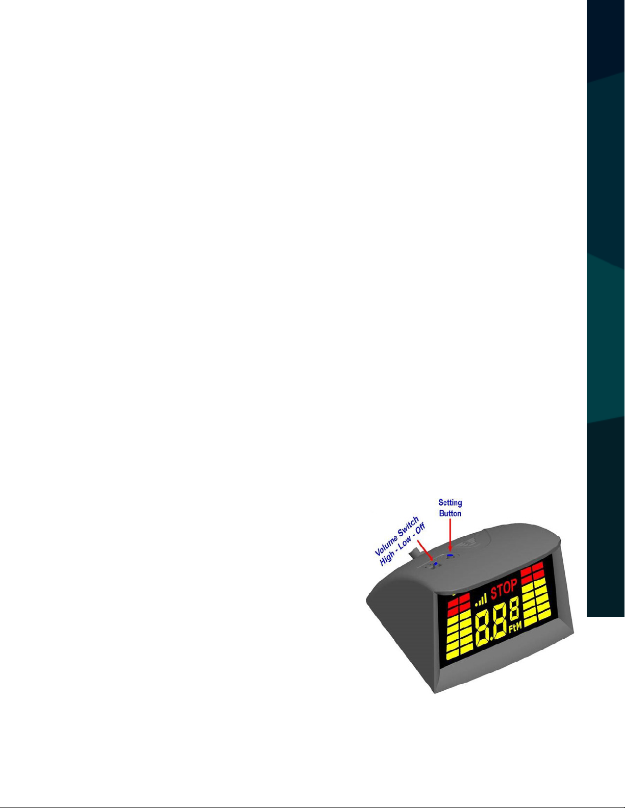
A) Adjusting Volume: The Volume Switch is
located on the top of the Monitor. Adjust the
alarm volume at one of 3 levels: High, Low or
MONITOR INSTALLATION
O (refer to Fig 27).
B) Setting Metric or Feet: By pushing the
Setting Button twice, the distance can be
displayed either in meters or in feet.
C) Truck & Trailer Exchange (Wireless Only):
Reverse With Condence ™
Fig 27: Monitor Switch
& Button
23
Page 24

This function is designed for vehicles which may work with a multitude of
trailers. The Monitor works with the ECU as a default setting, however, when
the Monitor of the vehicle has to work with another set of ECU/
Sensors (installed in another trailer), you must Fig 27: Monitor Switch &
Button sync to the new ECU and Sensors by pressing and holding the Setting
Button when the reverse gear is engaged (or however the ECU is powered),
until the Monitor shows the ECU ID number, then let go.
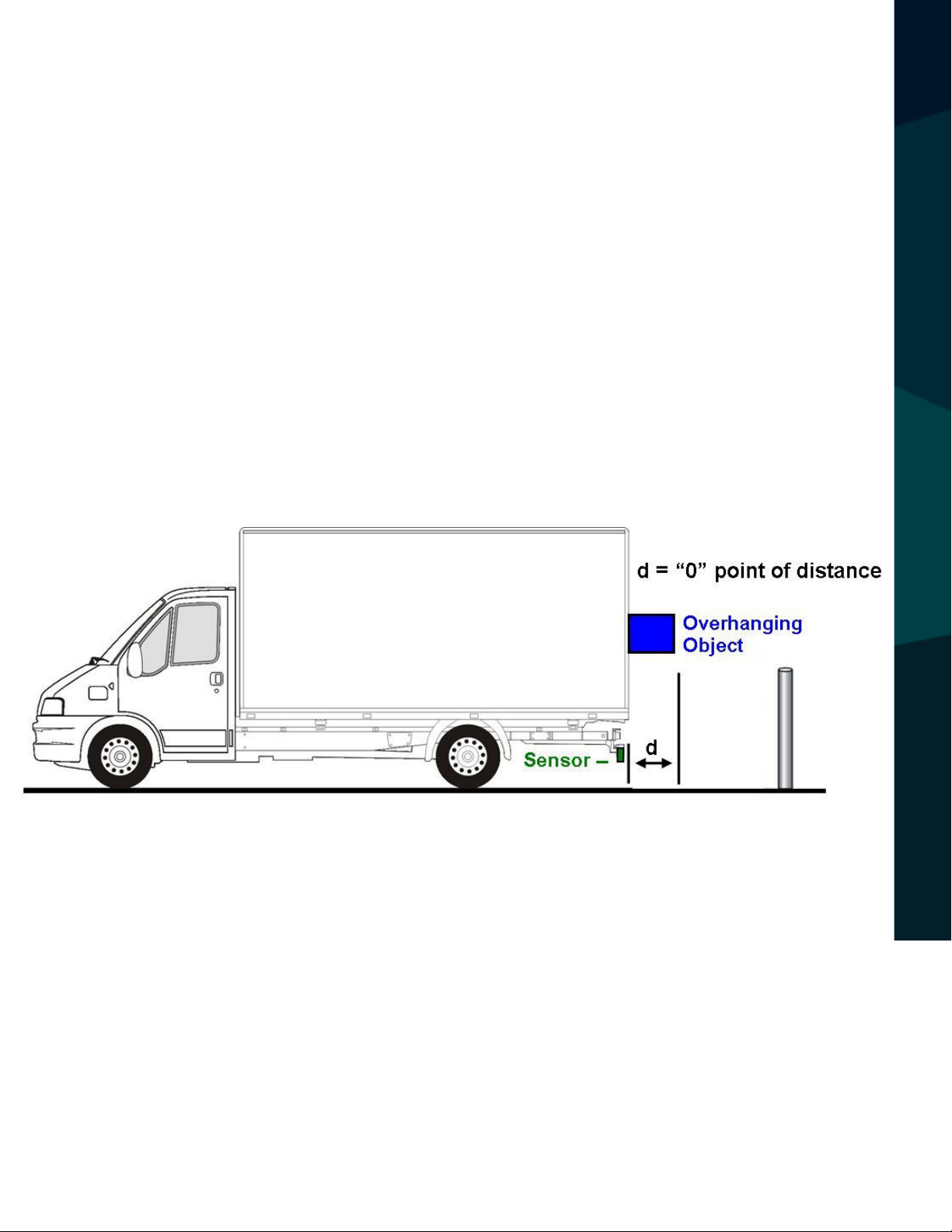
D) Understanding Stop-line Adjustment: This function is designed for
adjusting the stop line of the obstacle detection system. Obstacle Sensor
systems usually report the distance from the bumper to obstacles, so the
bumper or exactly the Sensor surface is the “0” point of distance (indicated as
"d" in Fig 28). With this function, the so-called “0” point itself can be extended from 0 (zero) up to 31 inches (0.8m), enabling you to change the stop line
accordingly. In some circumstances, for instance, when the vehicle has a rear
carrier or similar item, the “0” point should be extended. By doing so, the
Sensor system doesn’t report the carrier, but reports the accurate distance
from the obstacle to the carrier, instead of to the bumper. See the following
procedure for setting the Stop-line Adjustment.
Setting Stop-line Adjustment
SETTING STOP-LINE ADJUSTMENT
A) Press and hold Setting Button, before and while turning the vehicle key
to the ACC position. In 3 seconds, the warning unit will indicate the numeric
value of the previous “0” point of distance.
B) Each time you press the button, the displayed “0” point of distance (d)
increases by 1”, up to 35” (0.01m, up to 0.8m), and then starts at 0 (zero) again.
However if you press and hold the button for about 2 seconds, the value will
increase automatically, hold the button until the value reaches the desired
24
Rear View Safety
Page 25
corrected distance and ne tune as needed. Refer to Fig 28 below for further
clarication.
C) After the button is released, wait for 5 seconds, the new value will be effective automatically.
NOTE: Be aware that the Stop-line Adjustment remains as programmed
and does not re-set automatically. Stop-line Adjustment does not prevent the sensor from detecting an object. If the sensor is detecting
the overhanging object, it will continue to do so after
Stop-line Adjustment.
INSTALLATION TEST (IN ORDER SHOWN)
Fig 28: Stop-line Adjustment
Installation Test (in order shown)
A) Initial Test: With the vehicle in park and your foot on the brake, shift the
vehi-cle into reverse. The display (which remains blank at all other times) will
turn on and begin the Automatic Self-Test. It will be helpful to have an observer assist you in testing the unit the rst time by having them carefully walk
Reverse With Condence ™
25
Page 26

behind the vehicle. When doing so, each of the individual four (4) Sensor icons
will indicate (by ashing) when the assistant is closet to a particular Sensor.
The distance in feet and inches will also indicate when the individual is within
8 feet of a Sensor.
B) Volume Adjustment: Slide the Volume Switch (found on top of the LED
Moni-tor) to preferably the “High” volume setting in order to make sure it is
suciently loud.
C) Backing Test: Once the above is completed, test the system by placing
the vehicle in reverse with nothing behind it for at least 8 feet. The LED Monitor will turn on and run a Self-Test (see Automatic Self-Test under Systems
Operation). Once completed (takes about 2 seconds), the icon and distance
measurement will not display since no object is within 8 feet of the Sensors.
Begin backing up and as soon as an object is detected the Sensor icons and
distance measurement will appear on the LED Monitor. One of the four (4)
Sensor icons will be ashing (the one that is closest to an object) and the distance to that object is displayed as well.
NOTE: Audibly indicates only when an object is within 5’7” of Sensor 2 & 3
(two center Sensors) and 3’3” inches of Sensor 1 & 4 (two outer Sensors).
SYSTEM OPERATION
System Operation
A) Automatic Self-Test: Whenever the system is enabled (by placing the
vehicle in reverse), it will perform a self-test. Any Sensors that are blocked or
inoperable will display an error message denoted by E1, E2, E3 or E4 (Sensors
numbered left to right facing the back of the vehicle). After the self-test, the
system will automatically remove the icon display of any inoperable Sensor(s)
26
Rear View Safety
Page 27

and begin operating (even when a Sensor is malfunctioning). For example, if E4
were malfunctioning, the re-maining three Sensors would be displayed.
B) Inoperable Sensor: If any of the Sensor icons are not displayed, attend to
the repair of that Sensor immediately. In the case of an inoperable Sensor, do
not back up without walking around the vehicle rst and proceed with extreme
caution.
C) Blocked Sensor: Carefully remove any snow, ice or dirt that may have built
up on an inoperable Sensor. When placed in reverse the system will retest the
Sensors indicating if the problem still exists.
D) Minimum Detection Distance: The minimum detection and display distance is 8.7 inches (22cm); a person (or an object) can be detected most reliably
within 67 inches (1.7M) behind the vehicle or less.
E) Relative Accuracy: The display indicates the distance with 1.0 inch accuracy and shows the relative location of the obstacle (4 zones). For example, if
there is an object within range of the left side rear of the vehicle, the S1 icon
will indicate by ashing and displaying the distance in feet and inches. If the
object is moving to the right, the display will adjust in real time to indicate this
movement.
F) Detection Range: The middle Sensors (S2 & S3) start audible warning from
67 inches (1.7M); the corner Sensors (S1 & S4) start audible alarm at 39 inches
(1.0M).
SYSTEM OPERATION
CAUTION: The system will never alert you to any obstacles behind a malfunctioning Sensor; the icon for that Sensor will not be displayed on the Monitor.
Reverse With Condence ™
27
Page 28

ONE YEAR WARRANTY
REAR VIEW SAFETY, INC. WARRANTS THIS PRODUCT AGAINST MATERIAL DEFECTS FOR A
PERIOD OF ONE YEAR FROM DATE OF PURCHASE. WE RESERVE THE RIGHT TO REPAIR OR
REPLACE ANY SUCH DEFECTIVE UNIT AT OUR SOLE DISCRETION. REAR VIEW SAFETY, INC.
IS NOT RESPONSIBLE FOR A DEFECT IN THE SYSTEM AS A RESULT OF MISUSE, IMPROPER
INSTALLATION, DAMAGE OR MISHANDLING OF THE ELECTRONIC COMPONENTS. REAR VIEW
SAFETY, INC. IS NOT RESPONSIBLE FOR CONSEQUENTIAL DAMAGES OF ANY KIND.
THIS WARRANTY IS VOID IF: DEFECTS IN MATERIALS OR WORKMANSHIP OR DAMAGES
RESULT FROM REPAIRS OR ALTERATIONS WHICH HAVE BEEN MADE OR ATTEMPTED BY
OTHERS OR THE UNAUTHORIZED USE OF NONCONFORMING PARTS; THE DAMAGE IS DUE
TO NORMAL WEAR AND TEAR, THIS DAMAGE IS DUE TO ABUSE, IMPROPER MAINTENANCE,
NEGLECT OR ACCIDENT; OR THE DAMAGE IS DUE TO USE OF THE REAR VIEW SAFETY, INC.
SYSTEM AFTER PARTIAL FAILURE OR USE WITH IMPROPER ACCESSORIES.
WARRANTY PERFORMANCE
DURING THE ABOVE WARRANTY PERIOD, SHOULD YOUR REAR VIEW SAFETY PRODUCT
EXHIBIT A DEFECT IN MATERIAL OR WORKMANSHIP, SUCH DEFECT WILL BE REPAIRED WHEN
THE COMPLETE REAR VIEW SAFETY, INC. PRODUCT IS RETURNED, POSTAGE PREPAID AND
INSURED, TO REAR VIEW SAFETY, INC. OTHER THAN THE POSTAGE AND INSURANCE
REQUIREMENT, NO CHARGE WILL BE MADE FOR REPAIRS COVERED BY THIS WARRANTY.
WARRANTY DISCLAIMERS
NO WARRANTY, ORAL OR WRITTEN, EXPRESSED OR IMPLIED, OTHER THE ABOVE WARRANTY
IS MADE WITH REGARD TO THIS REAR VIEW SAFETY, INC. REAR VIEW SAFETY, INC. DISCLAIMS
WARRANTY
ANY IMPLIED WARRANTY OR MERCHANTABILITY OR FITNESS FOR A PARTICULAR USE OR
PURPOSE AND ALL OTHER WARRANTIES IN NO EVENT SHALL REAR VIEW SAFETY. INC.
LIABLE FOR ANY INCIDENTAL, SPECIAL, CONSEQUENTIAL, OR PUNITIVE DAMAGES OR FOR
ANY COSTS, ATTORNEY FEES, EXPENSES, LOSSES OR DELAYS ALLEGED TO BE AS A
CONSEQUENCE OF ANY DAMAGE TO, FAILURE OF, OR DEFECT IN ANY PRODUCT INCLUDING,
BUT NOT LIMITED TO, ANY CLAIMS FOR LOSS OF PROFITS.
28
Rear View Safety
Page 29

DISCLAIMER
REAR VIEW SAFETY AND/OR ITS AFFILIATES DOES NOT GUARANTEE OR PROMISE THAT THE
USER OF OUR SYSTEMS WILL NOT BE IN/PART OF AN ACCIDENT OR OTHERWISE NOT COLLIDE
WITH AN OBJECT AND/OR PERSON. OUR SYSTEMS ARE NOT A SUBSTITUTE FOR CAREFUL
AND CAUTIOUS DRIVING OR FOR THE CONSISTENT ADHERENCE TO ALL APPLICABLE TRAFFIC
LAWS AND MOTOR VEHICLE SAFETY REGULATIONS. THE REAR VIEW SAFETY PRODUCTS ARE
NOT A SUBSTITUTE FOR REARVIEW MIRRORS OR FOR ANY OTHER MOTOR VEHICLE
EQUIPMENT MANDATED BY LAW. OUR CAMERA SYSTEMS HAVE A LIMITED FIELD OF VISION
AND DO NOT PROVIDE A COMPREHENSIVE VIEW OF THE REAR OR SIDE AREA OF THE VEHICLE.
ALWAYS MAKE SURE TO LOOK AROUND YOUR VEHICLE AND USE YOUR MIRRORS TO CONFIRM
REARWARD CLEARANCE AND THAT YOUR VEHICLE CAN MANEUVER SAFELY. REAR VIEW
SAFETY AND/OR ITS AFFILIATES SHALL HAVE NO RESPONSIBILITY OR LIABILITY
FOR DAMAGE AND/OR INJURY RESULTING FROM ACCIDENTS OCCURRING WITH VEHICLES
HAVING SOME OF REAR VIEW SAFETY PRODUCTS INSTALLED AND REAR VIEW SAFETY AND/
OR ITS AFFILIATES, THE MANUFACTURER, DISTRIBUTOR AND SELLER SHALL NOT BE LIABLE
FOR ANY INJURY, LOSS OR DAMAGE, INCIDENTAL OR CONSEQUENTIAL, ARISING OUT OF THE
USE OR INTENDED USE OF THE PRODUCT. IN NO EVENT SHALL REAR VIEW SAFETY AND/OR
ITS AFFILIATES HAVE ANY LIABILITY FOR ANY LOSSES WHETHER DIRECT OR INDIRECT, IN
CONTRACT, TORT OR OTHERWISE INCURRED IN CONNECTION WITH THE SYSTEMS,
INCLUDING BUT NOT LIMITED TO DAMAGED PROPERTY, PERSONAL INJURY AND/OR LOSS OF
LIFE. NEITHER SHALL REAR VIEW SAFETY AND/OR ITS AFFILIATES HAVE ANY
RESPONSIBILITY FOR ANY DECISION, ACTION OR INACTION TAKEN BY ANY PERSON IN
RELIANCE ON REAR VIEW SAFETY SYSTEMS, OR FOR ANY DELAYS, INACCURACIES AND/OR
ERRORS IN CONNECTION WITH OUR SYSTEMS FUNCTIONS.
DISCLAIMER
Reverse With Condence ™
29
Page 30

If you have any questions
about this product, contact:
Rear View Safety, Inc.
1797 Atlantic Avenue
Brooklyn, NY 11233
800.764.1028
30
Better Cameras. Better Service.
IT’S OUR GUARANTEE.
Rear View Safety
 Loading...