

Page 1
SenseStat Wireless User Guide
About the Monitor
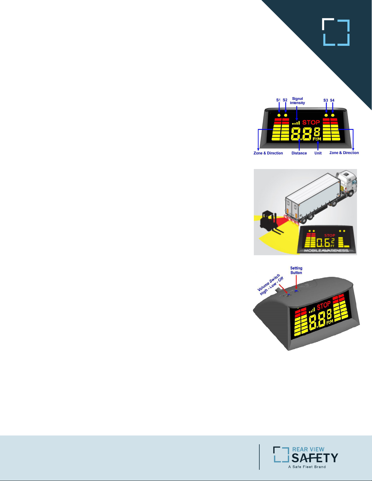
The Monitor consists of a bright LED display having 4 individual
bar (Sensor) indicators and a distance meter. The advanced
capabilities of the system are designed such that the dash
mounted display will indicate the distance (in feet & inches or
meters) of the Sensor that is closest to an object along with an
audible alert at a certain distance (see chart below). The yellow
dot at the top of the Sensor (S1, S2, S3 or S4) that is closest to an
object will flash while the distance to the object is indicated on
the display. As the vehicle is moving, if an object becomes closer
to a different Sensor, the yellow dot over that Sensors bar will
flash and indicate its distance to the new closest object.
• Indication of Sensors: S1, S2, S3, S4 indicate Sensor locations
from left to right
• Indication of Direction and Zone: The 4 LED column bars show
the Direction and Zone (Sensor) of the obstacle
• Indication of Distance: Shows the distance from the Sensor to
the obstacle in meters or in feet & inches of the Sensor that is
closest to an object
• Signal Intensity: Shows the signal strength
• Unit: Displays the unit of measurement being used, feet or
eters
m
How to Sync
SenseStat Wireless makes “drop and hitch” simple with it’s
advanced syncing technology. Once synced, the tractor and
trailer will continue to communicate. When hitching to a new
trailer, you will need t
steps below.
1. Hitch up to your new trailer and ensure the trailer has power.
2. Shift into reverse. The ECU is powered off of a +12VDC source
that’s on while in reverse.
3. While in reverse, and the ECU being powered, press and hold
the Setting Button on top of the monitor. While pressing the
button, a 3 digit code consisting of num-bers and letters should
display.
yellow tag displaying the ECU ID of the ECU on the trailer, so
you’ll know you’re syncing to the correct ECU.
4. Once you see the code, the system is synced . You can now
release the button and start backing safely.
This is the ECU ID Code. Each trailer will also have a
o sync to the new ECU by following the
Rear View Safety | 1797 Atlantic Avenue | Brooklyn NY 11233
800.764.1028 | Sales@RearViewSafety.com | www.RearViewSafety.com
Page 2
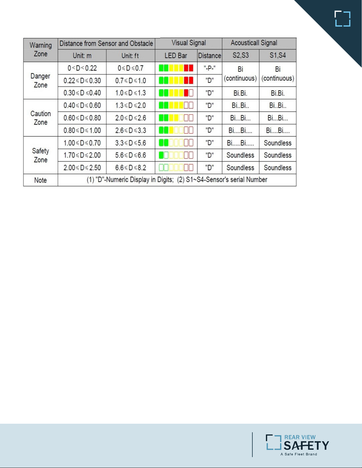
Sensor Visual and Audible Warnings
System Operation
A) Automatic Self-Test: Whenever the system is enabled (by placing the vehicle in reverse), it will
perform a self-test. Any Sensors that are blocked or inoperable will display an error message denoted by E1, E2, E3 or E4 (Sensors numbered left to right facing the back of the vehicle). After the
self-test, the system will automatically remove the icon display of any inoperable Sensor(s) and
begin operating (even when a Sensor is malfunctioning). For example, if E4 were malfunctioning,
the remaining three Sensors would be displayed.
B) Inoperable Sensor: If any of the Sensor icons are not displayed, attend to the repair of that Sensor
immediately. In the case of an inoperable Sensor, do not back up without walking around the vehicle
first and proceed with extreme caution.
C) Blocked Sensor: Carefully remove any snow, ice or dirt that may have built up on an
inoperable Sensor. When placed in reverse the system will retest the Sensors indicating if the
problem still exists.
D) Minimum Detection Distance: The minimum detection and display distance is 8.7 inches (22cm);
a person (or an object) can be detected most reliably within 67 inches (1.7M) behind the vehicle or
less.
E) Relative Accuracy: The display indicates the distance with 1.0 inch accuracy and shows the
rela-tive location of the obstacle (4 zones). For example, if there is an object within range of the left
side rear of the vehicle, the S1 icon will indicate by flashing and displaying the distance in feet and
inches. If the object is moving to the right, the display will adjust in real time to indicate this
movement.
F) Detection Range: The middle Sensors (S2 & S3) start audible warning from 67 inches (1.7M); the
corner Sensors (S1 & S4) start audible alarm at 39 inches (1.0M).
CAUTION: The system will never alert you to any obstacles behind a malfunctioning Sensor; the icon
for that Sensor will not be displayed on the Monitor.
Rear View Safety | 1797 Atlantic Avenue | Brooklyn NY 11233
800.764.1028 | Sales@RearViewSafety.com | www.RearViewSafety.com
Page 3

Troubleshooting
Possible Causes and Soluons
Ensure you have power to the Monitor and ECU as needed.
Double check all Sensor and power connections (see Fig 1).
Ensure the Monitor and ECU are properly synced.
Ensure the volume is turned up to a desired level and not muted.
Make sure the Sensors are free from obstruction and nothing is blocking the signal.
Make sure the Sensors are properly aligned. If the Sensors are mounted over 32 inches from the ground,
they may need to be aimed slightly downward, but no more than 5 degrees.
Make sure the Sensor surfaces are clean and clear of debris.
Make sure there are no sources of interference, such as those from ultrasonic or electromagnetic fields.
The Sensor operates at 40 kHz. Noise in or around that frequency may create interference.
Make sure sensor is properly aligned in bracket/mounting (see Fig 2).
Ensure the antenna is properly secured and connected to the ECU.
Make sure the antenna is installed in an open area and not in a crevice, cabinet, compartment or
other area of the vehicle’s body or frame.
Ensure the ECU and Monitor connections are secure. Poor connections could result in the ECU
losing power sporadically. If the ECU’s power drops below 7.5VDC, the ECU will turn off, resulting
in a signal drop on the Monitor until the Monitor shuts off due to no longer receiving any signal.
915 MHz
Fig 1: Sensor Connection
Fig 2: Sensor Alignment
Fig 3: ECU and Antennas
Fig 3: ECU and Antennas
Symptom
No Distance Readings
No Sound
Improper Readings
Signal Drop
What frequency does
the SenseStat Wireless
operate at?
Possible Causes and Soluons
Ensure you have power to the Monitor and ECU as needed.
Double check all Sensor and power connections (see Fig 1).
Ensure the Monitor and ECU are properly synced.
Ensure the volume is turned up to a desired level and not muted.
Make sure the Sensors are free from obstruction and nothing is blocking the signal.
Make sure the Sensors are properly aligned. If the Sensors are mounted over 32 inches from the ground,
they may need to be aimed slightly downward, but no more than 5 degrees.
Make sure the Sensor surfaces are clean and clear of debris.
Make sure there are no sources of interference, such as those from ultrasonic or electromagnetic fields.
The Sensor operates at 40 kHz. Noise in or around that frequency may create interference.
Make sure sensor is properly aligned in bracket/mounting (see Fig 2).
Ensure the antenna is properly secured and connected to the ECU.
Make sure the antenna is installed in an open area and not in a crevice, cabinet, compartment or
other area of the vehicle’s body or frame.
Ensure the ECU and Monitor connections are secure. Poor connections could result in the ECU
losing power sporadically. If the ECU’s power drops below 7.5VDC, the ECU will turn off, resulting
in a signal drop on the Monitor until the Monitor shuts off due to no longer receiving any signal.
915 MHz
800.764.1028 | Sales@RearViewSafety.com | www.RearViewSafety.com
Rear View Safety | 1797 Atlantic Avenue | Brooklyn NY 11233
 Loading...