

Page 1
Instruction Manual
Radar Object Detection System
RVS-123
Page 2
System Description...........................03
The Radar Object Detection System uses frequency modulated continuous
wave radar technology to detect stationary objects and people in blind spots.
This advanced system alerts the operator with both visual and audible
warnings. The system has three distinct length and width modes, enabling
SYSTEM DESCRIPTION
the operator to adjust the system to t their needs. The commercial grade
TABLE OF CONTENTS
Safety Information...........................04
Before Beginning Installation . . . . . . . . . . . . . . . . . . . . . . . 05
Radar Sensor Detection Range . . . . . . . . . . . . . . . . . . 06
Changing Detection Modes.......................07
Zone Introduction......................... 08-10
Accessories......................... .....11
Dimensions...........................12-13
Radar Sensor..............................14
Radar Sensor Specs...........................15
Radar Display Unit..........................16-17
Warranty & Disclaimer........................ 18-19
heavy-duty system has an IP69K waterproof rating and works perfectly in all
weather conditions.
Before permanently installing the system on the vehicle, verify that the
sensor mounting location provides a clear detection zone.
Take the vehicle to a clear area, temporarily attach the sensor in the
proposed mounting location, apply power to the system, and verify that
nothing is being detected. Our system is not aected if multiple systems are
operating in the same area or on the same vehicle, even if they are installed
in close proximity with overlapping detection ranges. There is no detection
of an object closer than approx. 0.3m to the sensor.
2 3
Rear View Safety Reverse With Condence ™
Page 3
If you have questions about this product, contact:
Before drilling please check that no cable or wiring is on the other side
of the wall. Please clamp all wires securely to reduce the possibility
Rear View Safety
1797 Atlantic Avenue
Brooklyn, NY 11233
Tel: 1.800.764.1028
IN NO EVENT SHALL SELLER OR MANUFACTURER BE
LIABLE FOR ANY DIRECT OR CONSEQUENTIAL DAMAGES OF
ANY NATURE, OR LOSSES OR EXPENSES RESULTING FROM
ANY DEFECTIVE PRODUCT OR THE USE OF ANY PRODUCT.
of them being damaged while vehicle is in use. Keep all cables away
from hot or moving parts and electrical noisy components.
We recommend doing a benchmark test before installation
to insure that all components are working properly.
PLEASE READ THE ENTIRE MANUAL AND FOLLOW THE INSTRUCTIONS AND
WARNINGS CAREFULLY. FAILURE TO DO SO CAN CAUSE SERIOUS DAMAGE
AND/OR INJURY, INCLUDING LOSS OF LIFE. BE SURE TO OBEY ALL APPLI
BEFORE YOU BEGIN
SAFETY INFORMATION
CABLE LOCAL TRAFFIC AND MOTOR VEHICLE REGULATIONS AS IT PERTAINS
TO THIS PRODUCT. IMPROPER INSTALLATION WILL VOID
MANUFACTURER’S WARRANTY.
4 5
Rear View Safety Reverse With Condence ™
Page 4
Radar Sensor Detection Range
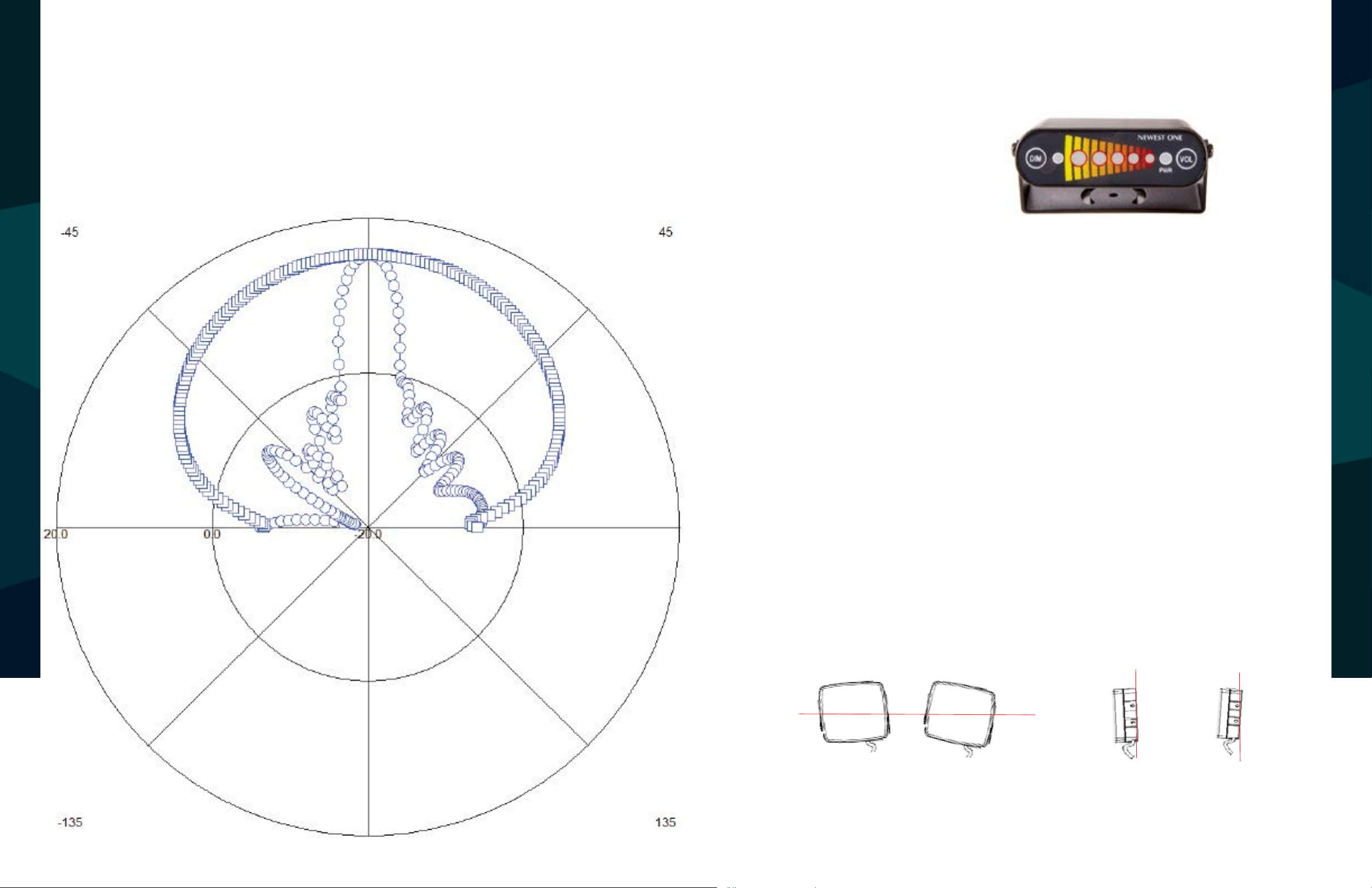
Antenna Beam angle
Horizontal : 80
Vertical : 10
Detection time : < 100ms
Radar Sensor Detection Range
Changing Detection Modes
System Description
perfectly in all weather conditions.
Installation
on the rear of the
1. Long press “Dim” and “Vol” together to adjust mode (LED will ash 3 times).
°(-3dB)
°(-3dB)
Antenna Radiation Pattern
2. Press “Dim” to toggle Mode 1 ~ Mode 3.
Mode 1: 3.5 x 4.0 (L) meter (3 zones)
Mode 2: 5.8 x 6.8 (L) meter (5 zones)
Mode 3: 7.0 x 8.0 (L) meter (5 zones)
3. Press “Vol” to save desired mode.
Button Explanation
1. Dim Button: Press “Dim” to adjust LED (3 steps)
CHANGING DETECTION MODES
2. Volume button: Press “Vol” to adjust volume
3. Factory Reset: Press “Dim” button before turning system on. LED 1 ~ 3 will ash sequentially.
Sensor Mounting
The installation site should be at. Ideally the radar sensor should be mounted on the rear of the
RADAR SENSOR DETECTION RANGE
vehicle as close to the center as possible at roughly 1 meter above the ground. The sensor should
be mounted in the upright position with the cable exit on the sensor pointing downwards.
Mounting Angle
Select the appropriate location to mount the sensor.
a. Height range (from ground); 1m +/- 0.3 m)
b. Vertical angle range +5 (up), -2° (down)
c. Horizontal angle range +/- 5
-5°
+5°
-2° +5°
6 7
Rear View Safety Reverse With Condence ™
Page 5

Mode 2
Zone 1
Zone 2
Zone 3
Zone 5
Zone 5
Zone 4
Mode 2.: 4 x 6.5 meter
(Detection zone 5)
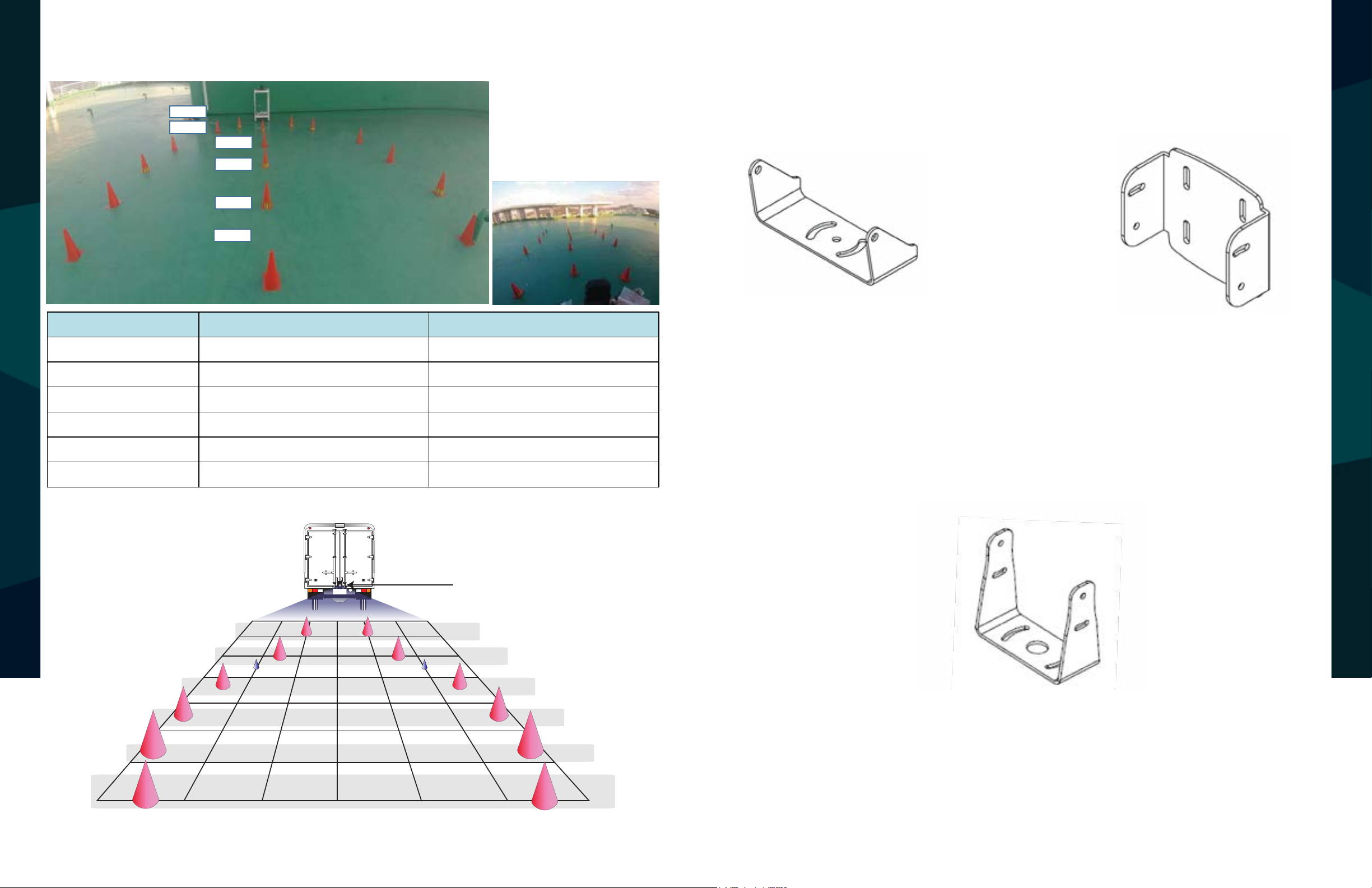
Test Conditions
Radar sensor (Height 1.0 meter)
Test Person : 1.8meter tall.
Centerline distance from the radar((m) Approximate width of the dtetection area (m)
Zone 1
(A Preliminary warning area)
6.5 meter 2.3 meter
Zone 2 5.8 meter 3.1 meter
Zone 3 4.6 meter 4.0 meter
Zone 4 3.4 meter 4.0 meter
Zone 5
(Collision area)
1.8 meter 3.4 meter
Zone 5
(Collision area)
0.6 meter 1.6 meter
Mode 1
(Collision area)
Zone 3
Mode 1.: 2.7 x 4meter
(Detection zone 3)
Test Conditions
Radar sensor (Height 1.0 meter)
Test Person : 1.8 meter tall
Zone 1
Zone 2
Zone 3
Zone 3
Mode 1
Centerline distance from the radar (m) Approximate width of the detection area (m)
Zone 1
(A Preliminary warning area)
4.0 meter 1.6 meter
Zone 2 3.5meter 2.4 meter
Zone 3
(Collision area)
2.0 meter 2.7 meter
Zone 3
(Collision area)
0.8 meter 1.9 meter
1 Area → 1㎡
Mode 1: 3.5 x 4.0 Meter (3 Detection Zones) Mode 2: 5.8 x 6.8 Meter (3 Detection Zones)
Mode 2
Zone 1
(A Preliminary warning area)
Zone 5
(Collision area)
Zone 5
(Collision area)
Zone 1
(A Preliminary warning area)
Zone 2 3.5 meter 1.6 meter
Zone 2 2.7 meter 3.5 meter
Mode 1.: 3.5 X 4.0 meter
(Detection zone 3)
Zone 3
Zone 1
Centerline distance from the radar (m) Approximate width of the detection area (m)
4.0 meter
Zone 3
Zone 2
Test Conditions
Radar sensor (Height 1.0 meter)
Test Person : 1.8 meter tall
Mode 2.: 5.8 X 6.8 meter
(Detection zone 5)
Zone 5
Zone 5
Zone 4
Zone 3
Zone 2
Zone 1
Centerline distance from the radar((m) Approximate width of the dtetection area (m)
6.8 meter
Zone 2 6.2 meter 2.3 meter
Zone 2 5.6 meter 4.4 meter
Zone 3 4.1 meter 5.8 meter
Test Conditions
Radar sensor (Height 1.0 meter)
Test Person : 1.8meter tall.
ZONE INTRODUCTION
ZONE INTRODUCTION
Zone 3
(Collision area)
1.6 meter 2.6 meter
0.8 meter 2.0 meter
Radar sensor
1m
ZONE 3
2m
3m
4m
ZONE 3
ZONE 2
ZONE 1
Zone 4 2.8 meter 4.5 meter
1.3 meter 2.7 meter
0.8 meter 2.0 meter
Radar sensor
1m
2m
ZONE 5
ZONE 5
3m
4m
5m
6m
ZONE 4
ZONE 3
ZONE 2
5m
7m
1 Area → 1㎡
8 9
Rear View Safety Reverse With Condence ™
ZONE 1
Page 6
Mode 3
Mode 3.: 5.5 x 7 meter
(Detection zone 5)
Test Conditions
Radar sensor (Height 1.0 meter)
Test Person : 1.8meter tall.
Zone 1
Zone 2
Zone 3
Zone 4
Zone 5
Zone 5
Centerline distance from the radar((m) Approximate width of the dtetection area (m)
Zone 1
(A Preliminary warning area)
7.0 meter 5.0 meter
Zone 2 5.8 meter 5.5 meter
Zone 3 4.5 meter 5.4 meter
Zone 4 3.4 meter 5.0 meter
Zone 5
(Collision area)
2.0 meter 3.4 meter
Zone 5
(Collision area)
0.8 meter 2.0 meter
Mode 3: 7.0 x 8.0 Meter (5 Detection Zones)
Zone 1
(A Preliminary warning area)
Zone 5
(Collision area)
Zone 5
(Collision area)
Mode 3
Zone 5
Zone 5
Zone 4
Zone 3
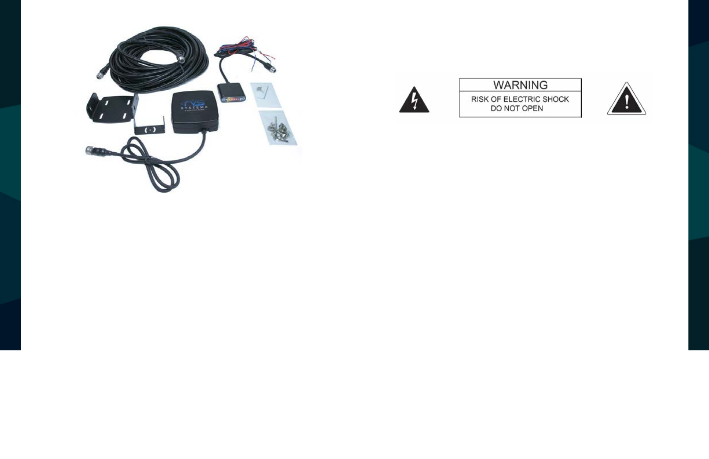
Accessories
Mode 3.: 7.0 X 8.0 meter
(Detection zone 5)
Test Conditions
Radar sensor (Height 1.0 meter)
Test Person : 1.8meter tall.
Zone 2
Zone 2 6.3 meter 7.0 meter
Zone 3 4.6 meter 7.0 meter
Zone 4 3.1 meter 6.0 meter
Zone 1
Centerline distance from the radar((m) Approximate width of the dtetection area (m)
8.0 meter
1.8 meter 3.8 meter
0.8 meter 2.0 meter
Display Unit
Bracket
Wall Mount
ACCESSORIES
ZONE INTRODUCTION
7m
6m
5m
4m
3m
2m
Radar sensor
1m
ZONE 5
ZONE 5
1 Area → 1㎡
ZONE 4
ZONE 3
ZONE 2
Stand Bracket (Optional)
ZONE 1
10 11
Rear View Safety Reverse With Condence ™
Page 7

Dimensions
Dimension
IX
● Radar Sensor (mm)
Dimensions
110
Radar Bracket (mm)
BRACKET DIMENSIONS
DIMENSIONS
106
107
● Display units (mm)
33.9
COMPONENT DIMENSIONS
Radar Sensor (mm)
MOUNTS INCLUDED
DIMENSIONS
Display Bracket (mm)
Display Unit (mm)
12 13
Rear View Safety Reverse With Condence ™
Page 8

Radar Sensor
● Connector Pin out
3 2
4 1
GND
ALARM OUT
GND
VCC
RS485-A
RS485-B
NC
5
Radar Sensor Specs
Parameter Value Units Condition
Frequency 24.05 ~ 24.2 GHz
Modulation FMCW(Frequency Modulated Continuous Wave)
Power 5 V dc From display unit
Current Consumption <100 mA
Power On Time <200 ms
Detection Time <100 ms
Max Detection Range 8 m
Communication RS-485
Operating Temperature -40 ~ +85 °C
Waterproof Rating IP69K
RADAR SENSOR
Shock Rating TBD G
Dimension 4.3” (H) x 4.2” (L) x
COMPONENT DIMENSIONS
RADAR SENSOR SPECS
1.3” (D)
Housing Material Polycarbonate
BRACKET DIMENSIONS
RADAR SENSOR
Trigger output - Controls when other equipment (such as an alarm, is activated.
14 15
Rear View Safety Reverse With Condence ™
Weight 390g w/o bracket
RADAR SENSOR SPECS
720g with bracket
Page 9
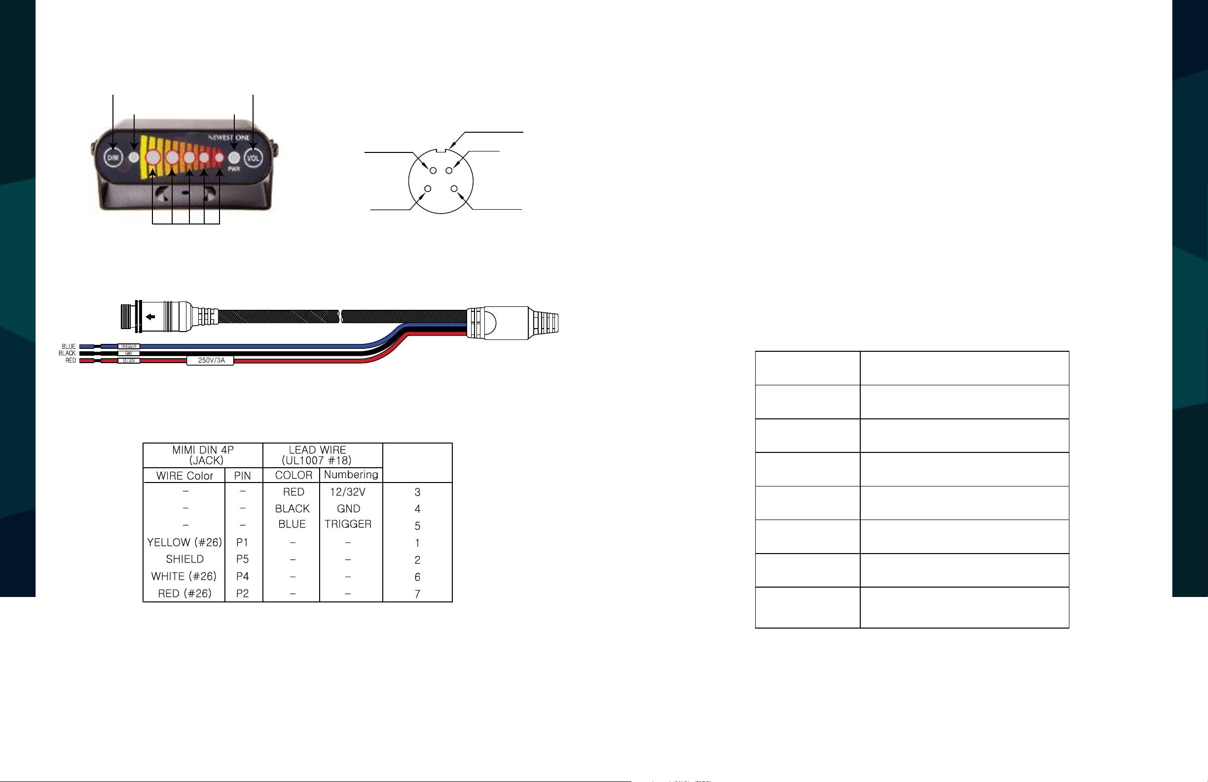
Radar Display Unit
Radar Display units
Radar Display units
IV
● Connector Pin out
● Connector Pin out
VCC
RS485-A
RS485-B
NC
1
2 3
4
5
GND
Volume button
Radar Display units
Radar Display units
IV
● Connector Pin out
● Rear Cable
● Pin Assignment
VCC
RS485-A
RS485-B
NC
1
2 3
4
5
GND
Dimmer button
CDS Sensor Power status LED
Volume button
Radar indication
Volume: Hold volume button for 3 seconds to mute system
Dimmer button
● Rear Cable
CDS Sensor Power status LED
Radar indication
Volume button
RS485-B
2 3
VCC
1
GND
5
4
NC
RS485-A
Power Status LED: Illuminates green continuously when
system is powered
Range Indications: LEDS move from left to right.
More illuminated LEDS indicate a closer object.
Dimmer Button: Use this button to adjust brightness of LED
Press Dim for 3 seconds to verify the current mode (LED 1 is least bright, LED 3 is most bright)
Long press Dim to verify saved mode (1 ~ 3)
Radar Display Unit Specs
Detection Zone 3 or 5 Zones
RADAR SENSOR SPECIFICATIONS
RADAR DISPLAY UNIT
● Pin Assignment
BRACKET DIMENSIONS
RADAR DISPLAY UNIT
● Cable connection
Red: + Vehicle power supply (3A fuse: Range +9 ~ +32V)
Black: Ground (Supply negative)
Blue : Activation input (Trigger from vehicle, High active)
Input Voltage 9 ~ 32V
Operating Temp. -30°C ~ +70°C
Cable Length 1.5M
Connector Deutsch or Screw Lock Type
Housing Material Polycarbonate
Dimensions 0.07” (H) x 1.9” (L) x 2.25” (D)
Weight 200g w/o bracket
220g with bracket
16 17
Rear View Safety Reverse With Condence ™
Page 10

ONE YEAR WARRANTY
DISCLAIMER
REAR VIEW SAFETY, INC. WARRANTS THIS PRODUCT AGAINST MATERIAL DEFECTS FOR A
PERIOD OF ONE YEAR FROM DATE OF PURCHASE. WE RESERVE THE RIGHT TO REPAIR OR
REPLACE ANY SUCH DEFECTIVE UNIT AT OUR SOLE DISCRETION. REAR VIEW SAFETY, INC.
IS NOT RESPONSIBLE FOR A DEFECT IN THE SYSTEM AS A RESULT OF MISUSE, IMPROPER
INSTALLATION, DAMAGE OR MISHANDLING OF THE ELECTRONIC COMPONENTS. REAR VIEW
SAFETY, INC. IS NOT RESPONSIBLE FOR CONSEQUENTIAL DAMAGES OF ANY KIND.
THIS WARRANTY IS VOID IF: DEFECTS IN MATERIALS OR WORKMANSHIP OR DAMAGES
RESULT FROM REPAIRS OR ALTERATIONS WHICH HAVE BEEN MADE OR ATTEMPTED BY
OTHERS OR THE UNAUTHORIZED USE OF NONCONFORMING PARTS; THE DAMAGE IS DUE
TO NORMAL WEAR AND TEAR, THIS DAMAGE IS DUE TO ABUSE, IMPROPER MAINTENANCE,
NEGLECT OR ACCIDENT; OR THE DAMAGE IS DUE TO USE OF THE REAR VIEW SAFETY, INC.
SYSTEM AFTER PARTIAL FAILURE OR USE WITH IMPROPER ACCESSORIES.
WARRANTY PERFORMANCE
DURING THE ABOVE WARRANTY PERIOD, SHOULD YOUR REAR VIEW SAFETY PRODUCT
EXHIBIT A DEFECT IN MATERIAL OR WORKMANSHIP, SUCH DEFECT WILL BE REPAIRED WHEN
THE COMPLETE REAR VIEW SAFETY, INC. PRODUCT IS RETURNED, POSTAGE PREPAID AND
INSURED, TO REAR VIEW SAFETY, INC. OTHER THAN THE POSTAGE AND INSURANCE
REQUIREMENT, NO CHARGE WILL BE MADE FOR REPAIRS COVERED BY THIS WARRANTY.
REAR VIEW SAFETY AND/OR ITS AFFILIATES DOES NOT GUARANTEE OR PROMISE THAT THE
USER OF OUR SYSTEMS WILL NOT BE IN/PART OF AN ACCIDENT OR OTHERWISE NOT COLLIDE
WITH AN OBJECT AND/OR PERSON. OUR SYSTEMS ARE NOT A SUBSTITUTE FOR CAREFUL
AND CAUTIOUS DRIVING OR FOR THE CONSISTENT ADHERENCE TO ALL APPLICABLE TRAFFIC
LAWS AND MOTOR VEHICLE SAFETY REGULATIONS. THE REAR VIEW SAFETY PRODUCTS ARE
NOT A SUBSTITUTE FOR REARVIEW MIRRORS OR FOR ANY OTHER MOTOR VEHICLE
EQUIPMENT MANDATED BY LAW. OUR CAMERA SYSTEMS HAVE A LIMITED FIELD OF VISION
AND DO NOT PROVIDE A COMPREHENSIVE VIEW OF THE REAR OR SIDE AREA OF THE VEHICLE.
ALWAYS MAKE SURE TO LOOK AROUND YOUR VEHICLE AND USE YOUR MIRRORS TO CONFIRM
REARWARD CLEARANCE AND THAT YOUR VEHICLE CAN MANEUVER SAFELY. REAR VIEW
SAFETY AND/OR ITS AFFILIATES SHALL HAVE NO RESPONSIBILITY OR LIABILITY
FOR DAMAGE AND/OR INJURY RESULTING FROM ACCIDENTS OCCURRING WITH VEHICLES
HAVING SOME OF REAR VIEW SAFETY PRODUCTS INSTALLED AND REAR VIEW SAFETY AND/
OR ITS AFFILIATES, THE MANUFACTURER, DISTRIBUTOR AND SELLER SHALL NOT BE LIABLE
FOR ANY INJURY, LOSS OR DAMAGE, INCIDENTAL OR CONSEQUENTIAL, ARISING OUT OF THE
USE OR INTENDED USE OF THE PRODUCT. IN NO EVENT SHALL REAR VIEW SAFETY AND/OR
ITS AFFILIATES HAVE ANY LIABILITY FOR ANY LOSSES WHETHER DIRECT OR INDIRECT, IN
CONTRACT, TORT OR OTHERWISE INCURRED IN CONNECTION WITH THE SYSTEMS,
INCLUDING BUT NOT LIMITED TO DAMAGED PROPERTY, PERSONAL INJURY AND/OR LOSS OF
LIFE. NEITHER SHALL REAR VIEW SAFETY AND/OR ITS AFFILIATES HAVE ANY
DISCLAIMER
DISCLAIMER
RESPONSIBILITY FOR ANY DECISION, ACTION OR INACTION TAKEN BY ANY PERSON IN
WARRANTY DISCLAIMERS
NO WARRANTY, ORAL OR WRITTEN, EXPRESSED OR IMPLIED, OTHER THE ABOVE WARRANTY
WARRANTY
IS MADE WITH REGARD TO THIS REAR VIEW SAFETY, INC. REAR VIEW SAFETY, INC. DISCLAIMS
RELIANCE ON REAR VIEW SAFETY SYSTEMS, OR FOR ANY DELAYS, INACCURACIES AND/OR
ERRORS IN CONNECTION WITH OUR SYSTEMS FUNCTIONS.
WARRANTY
ANY IMPLIED WARRANTY OR MERCHANTABILITY OR FITNESS FOR A PARTICULAR USE OR
PURPOSE AND ALL OTHER WARRANTIES IN NO EVENT SHALL REAR VIEW SAFETY. INC.
LIABLE FOR ANY INCIDENTAL, SPECIAL, CONSEQUENTIAL, OR PUNITIVE DAMAGES OR FOR
ANY COSTS, ATTORNEY FEES, EXPENSES, LOSSES OR DELAYS ALLEGED TO BE AS A
CONSEQUENCE OF ANY DAMAGE TO, FAILURE OF, OR DEFECT IN ANY PRODUCT INCLUDING,
BUT NOT LIMITED TO, ANY CLAIMS FOR LOSS OF PROFITS.
18 19
Rear View Safety Reverse With Condence ™
Page 11

If you have any questions
about this product, contact:
Rear View Safety, Inc.
1797 Atlantic Avenue
Brooklyn, NY 11233
800.764.1028
Better Cameras. Better Service.
IT’S OUR GUARANTEE.
 Loading...