

Page 1
USER’ S MANUAL
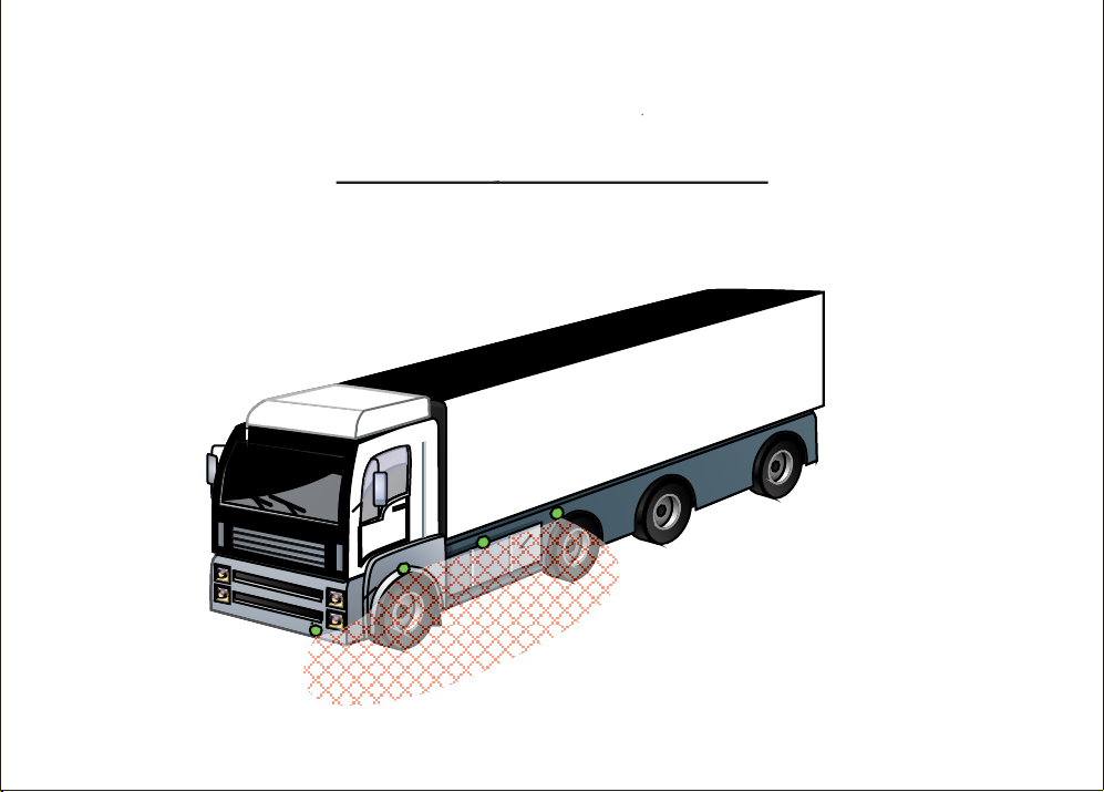
Pedestrian, Curbside Detection
RVS-117
Page 2
This system alerts the driver to potential hazards on the side of the
vehicle.
RVS-117
Note: Failure to follow instructions may lead to system
malfunction.
FEATURES
System will turn on when brakes are pressed.
System will turn on when right or left blinker is used
System has smart power on/off switch. It will power up
upon ignition start up, even if it was previously off.
Working Voltage
Rated Voltage
Rated Current
Sensor Type
Sensor Frequency
Sensor Quantity
Measurement Range
Sound Frequencies
Working Temp.
Storage Temp.
Waterproof Rating
16.0~28.0VDC
24.0VDC
50mA (230mA max)
Active Sensor
58KHz
4 pcs
0~2.0 (M)
1.0KHz
IP67
Page 3
RVS-117
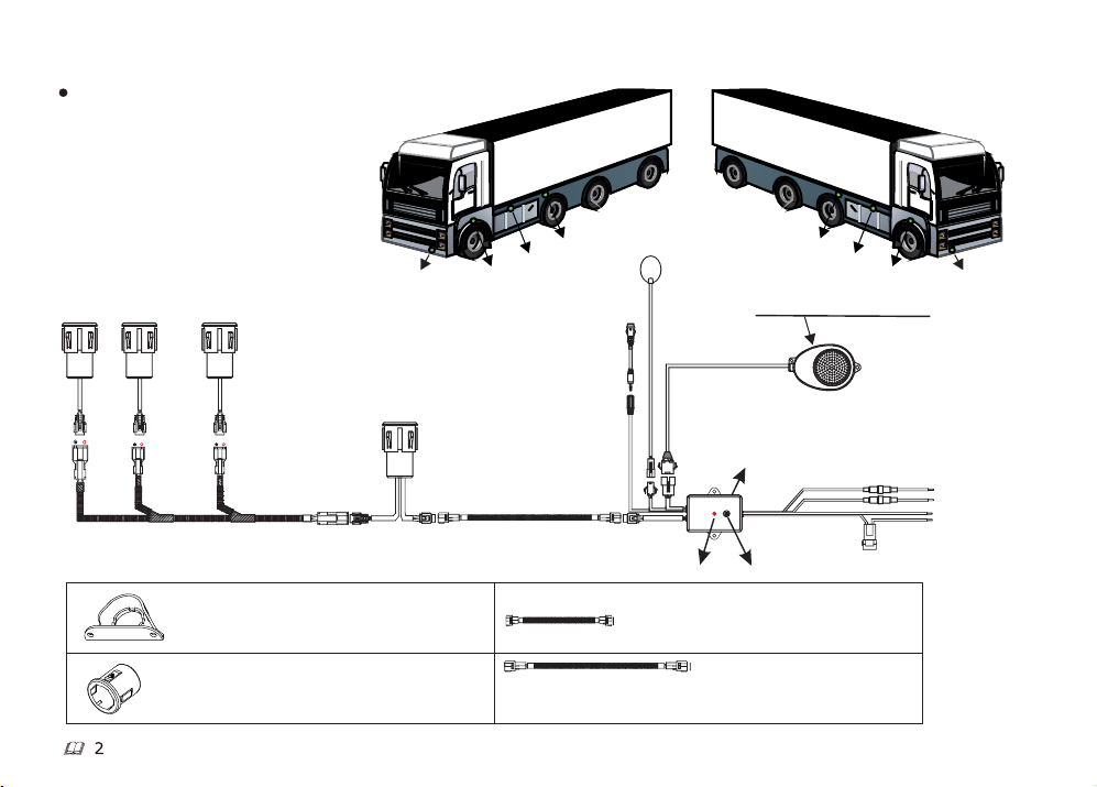
PRODUCT COMPOSITION
3 Normal Sensors (Detecting Unit)
1 main sensor (Detect and ECU)
1 assistant box (Power Supply)
1 Switch
1 LED Light (Warning Unit)
1 buzzer (Warning Unit)
All wires and necessary mounting parts
are included in the package.
4
3
2
Optional parts
Metal Bracket For Sensors
Sensor Sleeves (Rubber)
1
1
Main sensor
Left Hand DriveRight Hand Drive
4
3
2
LED Light
On/off Switch
*-Connect orange wire to right turn signal wire for Left hand drive vehicles
-Connect orange wire to left turn signal wire for Right hand drive vehicles
Assistant box
Power LED DIP switches
Sensor Extension Cable
1m
Sensor Extension Cable 2.5m
4
3
2
Sound level adjustment switch
Buzzer
1
Brake pedal input - Yellow
Turn signal* input - Orange
GND - Black
ACC(24V) - Red
Page 4

WARNING ZONE
Diagram-1:Warning zones
Zone
Zone3
Zone2
Zone1
Distance To Object
100~200cm
50~100cm
0~50cm
Timing of Audio Warning and
ON
Off
900ms
ON
Off
150ms
O
N
Off
INSTALLATION OF SENSORS
Install sensors on passenger side of car (opposite side of driver)
Refer to pictures below.
1.Drilling
Drill bit must be perpendicular to bumper when drilling hole.
Refer to Fig.3.
50ms
LED Light
100ms
50ms
50ms
900ms
150ms
100ms
50ms
Sound Code
Bi....Bi
Bi..Bi
B............i
2.Installation
2.1 The sensors are usually mounted on the bumper which is
perpendicular to the ground, or slightly upturned.
2.2 When installing, please note that the positioning column
must be upward, as shown in Fig. 4.
RVS-117
90°
Fig.3: Vertical Drilling
Vista A
Positioning rib
Upwards
Vista A
Fig.4:Sensor Installation
9
0°
Sensor
~95
°
Page 5

2.3 If the sensors are mounted in metal bumper, the sensors
should be wrapped with rubber sleeve before installation.
Positioning rib
Fig.5: Wrap the Sensor with Rubber Sleeve
2.4 Installation With Metal Bracket
Positioning rib
Metal Bracket
RVS-117
4
Page 6

RVS-117
3. Sensors Installation Spacing
As shown in Fig. 3, the sensors are mounted on the left side of the truck
(the driver's seat is on the right).
Space Sensors between 1m~2m apart
S 4
S 3
S 2
Right Hand Drive
S3S4
S2
Left Hand Drive
Fig. 6: Sensors Installation Spacing
4. Sensor Installation Height
As shown in Fig. 4, the sensors are mounted on the left side of the truck
(the driver's seat is on the right).
Sensor install height is 60cm~110cm.
S1
S4
S1
S2
S3
Ground
Fig. 7: Sensors Installation Height
S1
5
Page 7

RVS-117
(1) The system is designed and intended as a warning aid
(2) Our company shall accept no responsibility for any accidents and / or damage caused during the usage of this system.
(3) The detection results may be affected when the system works under very bad weather conditions (e.g strong wind, heavy rain,
snow, very low or high temperature) or on complicated roads (such as rugged roads or roads with slope).
(4) Keep the sensor surface clean. Water, ice or mud stayed on it may affect the performance.
(5) Ultrasonic and electromagnetic wave from other sources near the system may affect the detection results.
6
Page 8

RVS-117
How to Use
* When the ignition is started, the on/off light switch will come
on, and the system will go into standby.
* The buzzer will only activate if the indicator is engaged, the
brakes will not active the buzzer.
* If an object is detected, the LED light will flash, regardless
of if the brake or turn signal is being used.
* The system is always active except when the ignition is off
or it is manually turned off.
5. DIP switch settings of assistant box.
1 2
ON
1 2
(1), When DIP SW1 and SW2 are ON, the warning range for
buzzer is 0~50cm, The warning range for LED light is 0~200cm.
(2) When DIP SW1 is ON and SW2 is OFF, both the
warning range for buzzer and LED light is 0~200cm.
(3)When DIP SW1 and SW2 are OFF, both the warning
range for buzzer and LED light is 0~100cm.
(4) When DIP SW1 is OFF and SW2 is ON, the warning
range for buzzer is 0~50cm, for LED light is 0~100cm.
(5) If the unit is only getting a brake signal, buzzer will
not warn, and LED warning range is 0~100cm.
( OFF: ON: )
No.
1
2
3
4
Break pedal input
W1 SW2
S
ON
ON
OFF
O
OFF
OFFOFF
ON
BZ/LED
Buzzer
N
Buzzer
Buzzer
Buzzer
Buzzer
Zone 1
LED
LED
LED
LED
LED
0-50(cm)
Zone 2
50-100(cm)
100-200(cm)
Zone 3
7
 Loading...