

Page 1
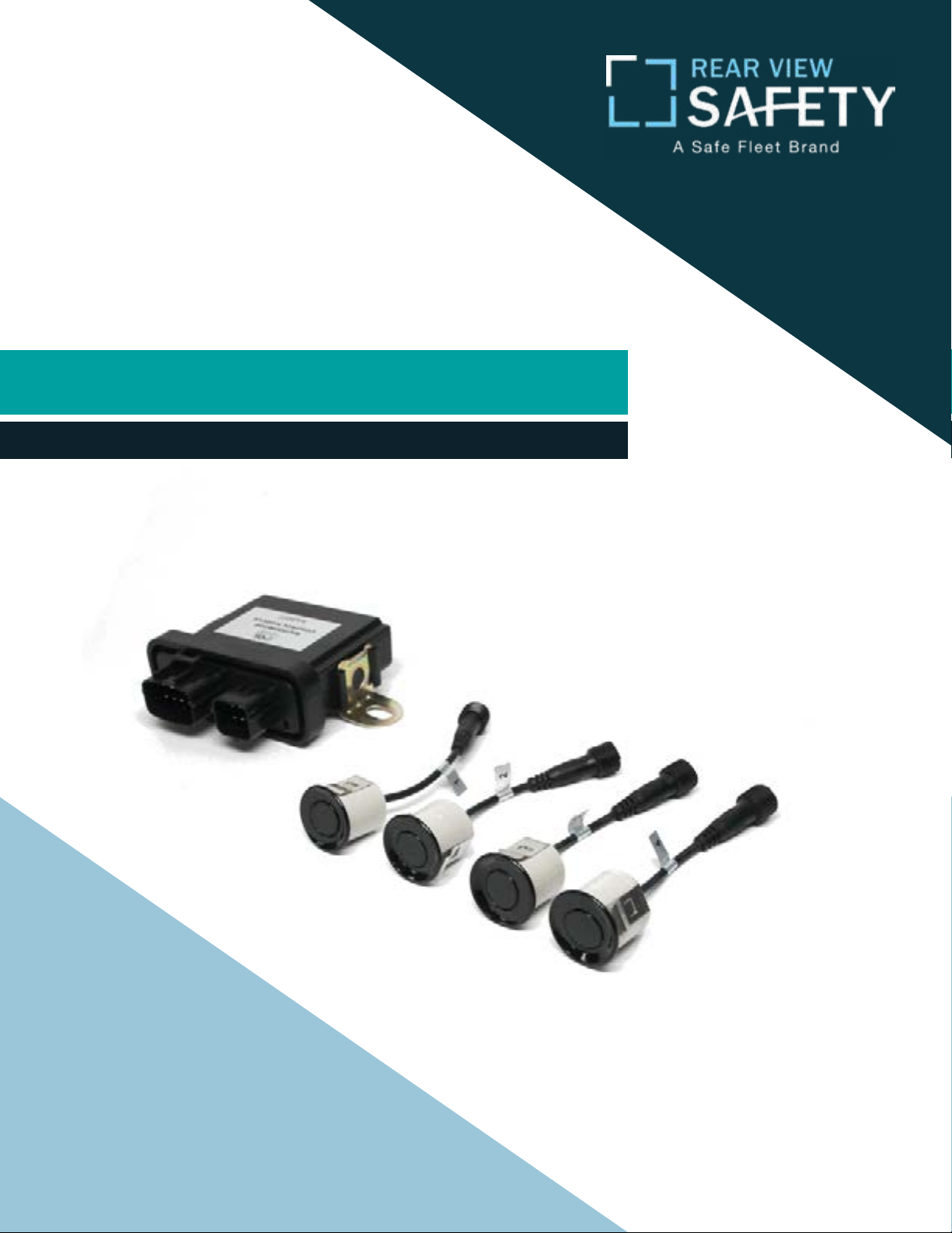
Instruction Manual
Waterproof Backup Sensor Reversing System
RVS-112-W
Rear View Safety, Inc. © 2018
Page 2
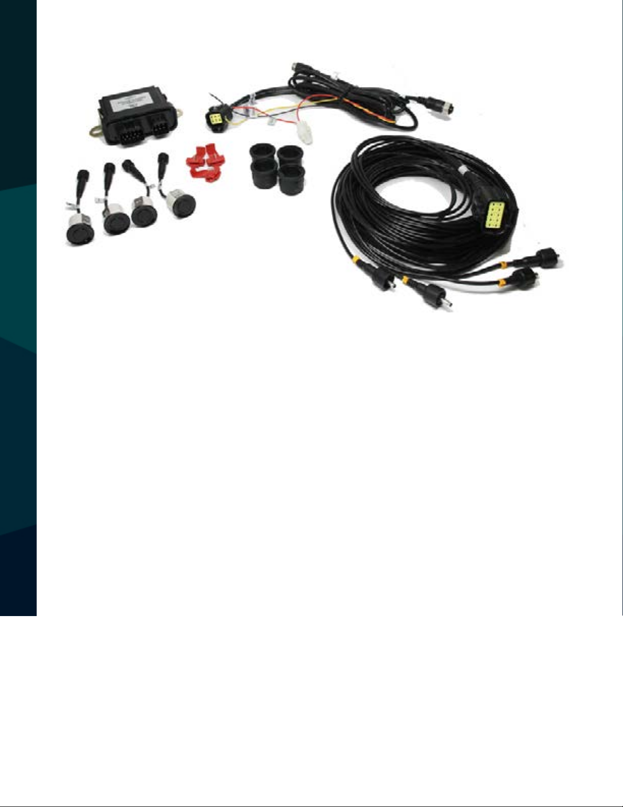
TABLE OF CONTENTS
System Description...........................03
Safety Information...........................04
Before Beginning Installation . . . . . . . . . . . . . . . . . . . . . . . 05
Setup........................... . . 06
Specications..............................07
Installation..............................08-09
Alternate Mounting........................ 10-11
Detection...............................12
Wiring Diagram........................ . . 13-14
Features........................ . . 15
Warranty & Disclaimer........................ 16-17
2
Rear View Safety
Page 3
The RVS-112-W Vehicle Reversing Aid is an automatic back up alert system
that warns drivers of potential obstacles while backing up their vehicle. Using
ultrasonic echo location sonar technology the system is activated when the
driver engages reverse gear. A 4 zone variable audio pulse alerts the driver of
potential obstacles. The audio pulse intensity increases and the audio frequency changes as the vehicle backs closer to the obstacle. As with all sensing systems there are blind areas in the sensing patterns due to the cone or triangular
nature in the way the sonar pulse is emitted. Whenever an object moves from a
covered area and into one of these blind areas a special warning alert message
and a very loud tone will be transmitted twice or until the operator takes the
SYSTEM DESCRIPTION
vehicle out of reverse. This is especially helpful for detecting moving objects
such as a pedestrian, an animal, a forklift or other moving vehicles that may be
behind your vehicle and in harms way.
Reverse With Condence ™
3
Page 4
SAFETY BASICS
If you have questions about this product, contact:
Rear View Safety
1797 Atlantic Avenue
Brooklyn, NY 11233
Tel: 1.800.764.1028
IN NO EVENT SHALL SELLER OR MANUFACTURER BE
4
LIABLE FOR ANY DIRECT OR CONSEQUENTIAL DAMAGES OF
ANY NATURE, OR LOSSES OR EXPENSES RESULTING FROM
ANY DEFECTIVE PRODUCT OR THE USE OF ANY PRODUCT.
Rear View Safety
Page 5

Before drilling please check that no cable or wiring is on the other side
of the wall. Please clamp all wires securely to reduce the possibility
of them being damaged while vehicle is in use. Keep all cables away
from hot or moving parts and electrical noisy components.
We recommend doing a benchmark test before installation
to insure that all components are working properly.
PLEASE READ THE ENTIRE MANUAL AND FOLLOW THE INSTRUCTIONS AND
WARNINGS CAREFULLY. FAILURE TO DO SO CAN CAUSE SERIOUS DAMAGE
AND/OR INJURY, INCLUDING LOSS OF LIFE. BE SURE TO OBEY ALL APPLI
CABLE LOCAL TRAFFIC AND MOTOR VEHICLE REGULATIONS AS IT PERTAINS
TO THIS PRODUCT. IMPROPER INSTALLATION WILL VOID
MANUFACTURER’S WARRANTY.
BEFORE YOU BEGIN
Reverse With Condence ™
5
Page 6

Sensors
Drill four holes at equal distance in the rear bumper and mount the
sensors using the included grommets. Run each cable to the sensor
box and plug each into its corresponding port.
Power
Connect Y-adapter to the waterproof control module. Connect the RED
wire to a 12V constant power and the GREEN wire to a 12V reverse
power. Connect the BLACK wire to a chassis ground.
Sensor Cable
The sensor cable attaches to the waterproof control module on one end
and the 4 sensors on the other.
The Multiplexer
The cable that runs through the vehicle now carries signals both from
the backup camera and the sensors. Plug this cable into port #3 in the
Multiplexer. In order to hear the sensor audio alerts, connect the blue
SETUP
trigger wire (coming o the multiplexer) to 12V reverse power.
6
Rear View Safety
Page 7

Sensor Specs
Sensor Type: Analog Sensor
Sensor Quantity: 4 Sensors
Sensor Frequency: 40kHz +/- kHz
Static Capacitance: 2000± 15%pF
Input Voltage max.: 140 Vp-p {at 40KHz)
Decay Time: <1.2ms
Decay Parameter : 20±3 (Admissible parameter)
Echo Sensitivity: >200mV
Horizontal Angle: 51° min.
Vertical Angle: 62° min.
Detection Range: 0.22mm (0.08ft) to 2.5m (8ft)
Working Voltage: 10.0 ~ 28.0 VDC
Rated Current (ECU): 60mA max
Wiring Harness: Vehicle Spec. T-Piece
Working Temperature: -40°C ~ +75°C
Storage Temperature: -40°C ~ +90°C
Waterproof Control Module Specs
Normal Voltage: 12 VDC
Operating Voltage: 1.0 ~ 28 VDC
Rated Current: 60 mA
Operating Frequency: 40 +/- 1 kHz
Housing Material: ABS
Housing Color: Black
Working Temperature: -40°C ~ 75°C
SPECIFICATIONS
Storage Temperature: -40°C ~ 90°C
Waterproof Rating: IP65
Reverse With Condence ™
7
Page 8

1) The width of vehicles vary. It is important to install the Sensors at
the appropriate distance and location along the rear bumper or equivalent Assuming that the width of vehicle is L, then the space between
Sensors is 1/4L (Sensors must be mounted S1, S2, S3, S4, from left to
right).
• Sensors S1 and S4 should be located approximately 1/8L from either
side of the vehicle. S2 and S3 will be located 1/4L from S1 and S4.
If the Sensors are mounted on a DOT type bumper, the Sensor locations are determined by the vehicle width (L), not the width of the
bumper. 2) Sensors should be mounted at an absolute minimum of 16
inches (40cm) to 32 inches (80cm) from the ground (20 inches (50cm)
is a good choice, if available). See Alternate Sensors Mounting Locations, for other options.
INSTALLATION
8
Rear View Safety
Page 9

Sensor Installation (In-Bumper Flush Mount)
For vehicles equipped with a bumper that can accommodate the Sensors,
carefully drill a 25mm hole and insert the Rubber Jacket, properly orientated
“UP”, in the hole rst. Then insert the Sensor, again properly orientated “UP”
Depending on the thickness and construction of the bumper, the hole diameter may need to be varied. The Rubber Jacket is designed to seat properly
into a 25mm hole with a 1/8 inch (3.2mm) thick metal bumper. If this is not
the case, the anges on the Rubber Jacket must be taken into consideration.
It is suggested that a test hole be utilized to conrm a proper t.
INSTALLATION
Reverse With Condence ™
9
Page 10

Alternate Sensor Mounting Locations
The system is designed to be installed with all 4 (four) Sensors aligned
across the rear of the vehicle, preferably at a height ranging from 16” to
32” from the ground. When the Sensors are installed in a dierent layout
(for example to detect a building overhang as shown below), please consider the following:
• Each Sensor detects objects in a circular area approximately 20” in di-
ameter.
• It is recommended that the face of all Sensors should be on the same
plane to ensure the accuracy of the system.
• When the Sensors are placed on two dierent levels (per the example
below) install S1 and S4 on the top and S2 and S3 on the bottom of the
vehicle.
ALTERNATE MOUNTING
10
Rear View Safety
Page 11

Sensors can also be mounted across the front of the vehicle to detect building
overhangs or to detect objects out of view.
NOTE: These sensors are a tool to help the driver. The driver should always
know what is in front of or behind them and physically check the area themselves.
Alternate Sensor Mounting Locations
ALTERNATE MOUNTING
CAUTION: Using less than 4 (four) Sensors across the width of a bumper will create limited coverage resulting in blind zones! It is strongly suggested that these blind zones
are mapped out to educate the driver regarding the system limitations.
Reverse With Condence ™
11
Page 12

Having all four Sensors in line, on the same plane, provides the best result. If you
break the Sensor conguration up, for example two on top and two on bottom,
you create a bigger gap between the Sensors, causing a large blind zone area.
This blind zone area can lead to objects or people being undetected by the Sensors.
Control Module Installation
1) Depending on the vehicle type, select an appropriate location to mount
the water-tight control module on the rear undercarriage of the truck chassis.
DETECTION
12
Rear View Safety
Page 13

For systems
with a multiplexer
WIRING DIAGRAM
Reverse With Condence ™
13
Page 14

For systems
with a power
harness
WIRING DIAGRAM
14
Rear View Safety
Page 15

Features
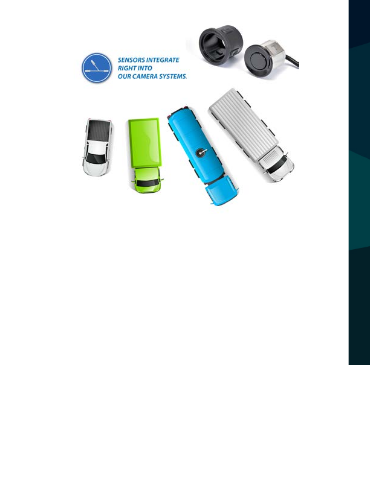
• Completely waterproof system - Install all components outside
• Four sensors mount to vehicle’s bumper
• Intelligent sensors - Ignore stationary, permanent objects
• Alerts you with distance to obstacles behind you
• Perfect for assisting in parking and tight driving
situations
FEATURES
Reverse With Condence ™
15
Page 16

ONE YEAR WARRANTY
REAR VIEW SAFETY, INC. WARRANTS THIS PRODUCT AGAINST MATERIAL DEFECTS FOR A
PERIOD OF ONE YEAR FROM DATE OF PURCHASE. WE RESERVE THE RIGHT TO REPAIR OR
REPLACE ANY SUCH DEFECTIVE UNIT AT OUR SOLE DISCRETION. REAR VIEW SAFETY, INC.
IS NOT RESPONSIBLE FOR A DEFECT IN THE SYSTEM AS A RESULT OF MISUSE, IMPROPER
INSTALLATION, DAMAGE OR MISHANDLING OF THE ELECTRONIC COMPONENTS. REAR VIEW
SAFETY, INC. IS NOT RESPONSIBLE FOR CONSEQUENTIAL DAMAGES OF ANY KIND.
THIS WARRANTY IS VOID IF: DEFECTS IN MATERIALS OR WORKMANSHIP OR DAMAGES
RESULT FROM REPAIRS OR ALTERATIONS WHICH HAVE BEEN MADE OR ATTEMPTED BY
OTHERS OR THE UNAUTHORIZED USE OF NONCONFORMING PARTS; THE DAMAGE IS DUE
TO NORMAL WEAR AND TEAR, THIS DAMAGE IS DUE TO ABUSE, IMPROPER MAINTENANCE,
NEGLECT OR ACCIDENT; OR THE DAMAGE IS DUE TO USE OF THE REAR VIEW SAFETY, INC.
SYSTEM AFTER PARTIAL FAILURE OR USE WITH IMPROPER ACCESSORIES.
WARRANTY
WARRANTY PERFORMANCE
DURING THE ABOVE WARRANTY PERIOD, SHOULD YOUR REAR VIEW SAFETY PRODUCT
EXHIBIT A DEFECT IN MATERIAL OR WORKMANSHIP, SUCH DEFECT WILL BE REPAIRED WHEN
THE COMPLETE REAR VIEW SAFETY, INC. PRODUCT IS RETURNED, POSTAGE PREPAID AND
INSURED, TO REAR VIEW SAFETY, INC. OTHER THAN THE POSTAGE AND INSURANCE
REQUIREMENT, NO CHARGE WILL BE MADE FOR REPAIRS COVERED BY THIS WARRANTY.
WARRANTY DISCLAIMERS
NO WARRANTY, ORAL OR WRITTEN, EXPRESSED OR IMPLIED, OTHER THE ABOVE WARRANTY
IS MADE WITH REGARD TO THIS REAR VIEW SAFETY, INC. REAR VIEW SAFETY, INC. DISCLAIMS
ANY IMPLIED WARRANTY OR MERCHANTABILITY OR FITNESS FOR A PARTICULAR USE OR
PURPOSE AND ALL OTHER WARRANTIES IN NO EVENT SHALL REAR VIEW SAFETY. INC.
LIABLE FOR ANY INCIDENTAL, SPECIAL, CONSEQUENTIAL, OR PUNITIVE DAMAGES OR FOR
ANY COSTS, ATTORNEY FEES, EXPENSES, LOSSES OR DELAYS ALLEGED TO BE AS A
CONSEQUENCE OF ANY DAMAGE TO, FAILURE OF, OR DEFECT IN ANY PRODUCT INCLUDING,
BUT NOT LIMITED TO, ANY CLAIMS FOR LOSS OF PROFITS.
16
Rear View Safety
Page 17

DISCLAIMER
REAR VIEW SAFETY AND/OR ITS AFFILIATES DOES NOT GUARANTEE OR PROMISE THAT THE
USER OF OUR SYSTEMS WILL NOT BE IN/PART OF AN ACCIDENT OR OTHERWISE NOT COLLIDE
WITH AN OBJECT AND/OR PERSON. OUR SYSTEMS ARE NOT A SUBSTITUTE FOR CAREFUL
AND CAUTIOUS DRIVING OR FOR THE CONSISTENT ADHERENCE TO ALL APPLICABLE TRAFFIC
LAWS AND MOTOR VEHICLE SAFETY REGULATIONS. THE REAR VIEW SAFETY PRODUCTS ARE
NOT A SUBSTITUTE FOR REARVIEW MIRRORS OR FOR ANY OTHER MOTOR VEHICLE
EQUIPMENT MANDATED BY LAW. OUR CAMERA SYSTEMS HAVE A LIMITED FIELD OF VISION
AND DO NOT PROVIDE A COMPREHENSIVE VIEW OF THE REAR OR SIDE AREA OF THE VEHICLE.
ALWAYS MAKE SURE TO LOOK AROUND YOUR VEHICLE AND USE YOUR MIRRORS TO CONFIRM
REARWARD CLEARANCE AND THAT YOUR VEHICLE CAN MANEUVER SAFELY. REAR VIEW
SAFETY AND/OR ITS AFFILIATES SHALL HAVE NO RESPONSIBILITY OR LIABILITY
FOR DAMAGE AND/OR INJURY RESULTING FROM ACCIDENTS OCCURRING WITH VEHICLES
HAVING SOME OF REAR VIEW SAFETY PRODUCTS INSTALLED AND REAR VIEW SAFETY AND/
OR ITS AFFILIATES, THE MANUFACTURER, DISTRIBUTOR AND SELLER SHALL NOT BE LIABLE
FOR ANY INJURY, LOSS OR DAMAGE, INCIDENTAL OR CONSEQUENTIAL, ARISING OUT OF THE
USE OR INTENDED USE OF THE PRODUCT. IN NO EVENT SHALL REAR VIEW SAFETY AND/OR
ITS AFFILIATES HAVE ANY LIABILITY FOR ANY LOSSES WHETHER DIRECT OR INDIRECT, IN
CONTRACT, TORT OR OTHERWISE INCURRED IN CONNECTION WITH THE SYSTEMS,
INCLUDING BUT NOT LIMITED TO DAMAGED PROPERTY, PERSONAL INJURY AND/OR LOSS OF
LIFE. NEITHER SHALL REAR VIEW SAFETY AND/OR ITS AFFILIATES HAVE ANY
RESPONSIBILITY FOR ANY DECISION, ACTION OR INACTION TAKEN BY ANY PERSON IN
RELIANCE ON REAR VIEW SAFETY SYSTEMS, OR FOR ANY DELAYS, INACCURACIES AND/OR
ERRORS IN CONNECTION WITH OUR SYSTEMS FUNCTIONS.
DISCLAIMER
Reverse With Condence ™
17
Page 18

If you have any questions
about this product, contact:
Rear View Safety, Inc.
1797 Atlantic Avenue
Brooklyn, NY 11233
800.764.1028
Better Cameras. Better Service.
IT’S OUR GUARANTEE.
 Loading...