

Page 1
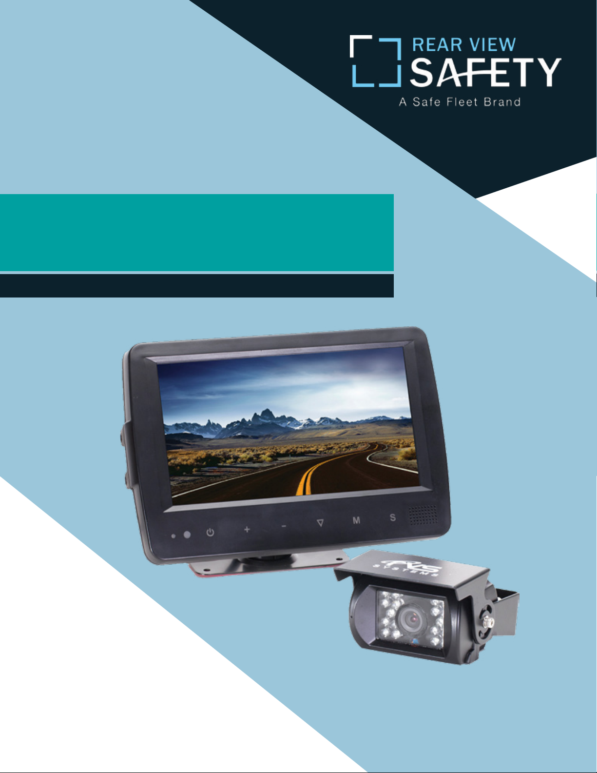
Instruction Manual
Backup Camera System
with Waterproof Monitor
RVS-7709900
Reverse With Condence ™
Rear View Safety, Inc. © 2016
1
Page 2
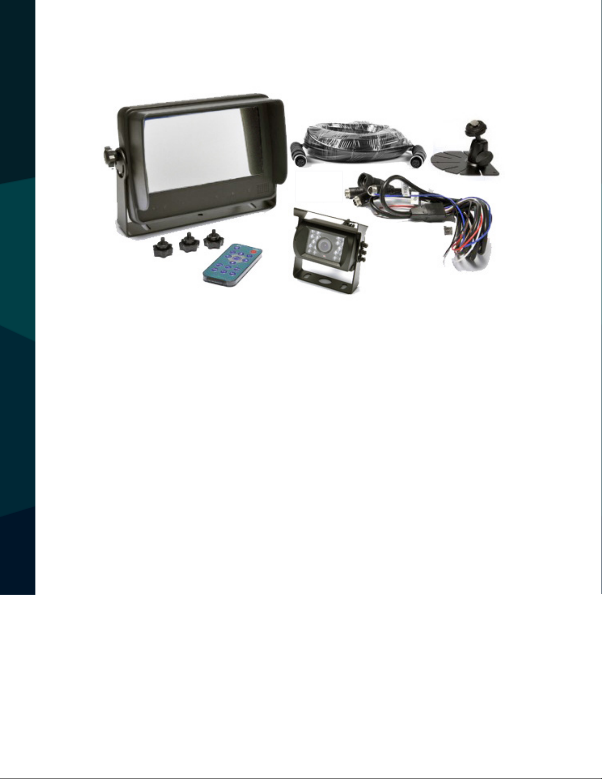
TABLE OF CONTENTS
Introduction...............................03
Safety Information..........................04-06
Before Beginning Installation . . . . . . . . . . . . . . . . . . . . . . . 07
Installation Guide.......................... 08-09
Accessories...............................10-11
Monitor Specication..........................12
Monitor Installation...........................13
Connections .............................14
Monitor Buttons............................15
Remote Operations .........................16-17
Wiring . . . ...............................18
Trigger Setting . . . . .........................19
Distance Grid Lines . . . . .........................20
2
Menu ...............................21-26
Camera Specication........................27-28
Troubleshooting............................29
Warranty & Disclaimer........................ 30-31
Rear View Safety
Page 3

NOTE!
Please read all of the installation instructions
carefully before installing the product. Improper
installation will void manufacturer’s warranty.
Congratulations on purchasing a Rear View Backup
Camera System!
With this manual you will be able to properly install and
operate the unit.
The Backup Camera System is intended to be installed as a
supplement aid to your standard rear view mirror that already exists
in your vehicle. The Backup Camera System should not be used as a
substitute for the standard rear view mirror or for any other mirror
that exists in your vehicle.
In some jurisdictions, it is unlawful for a person to drive a
motor vehicle equipped with a TV viewer or screen located forward of
the back of the driver’s seat or in any location that is visible, directly
or indirectly, to the driver while operating the vehicle.
INTRODUCTION
Reverse With Condence ™
3
Page 4

Please read the entire manual and follow the instructions and
warnings carefully. Failure to do so can cause serious damage and/or
injury, including loss of life. Be sure to obey all applicable local
trac and motor vehicle regulations as it pertains to this product.
Improper installation will void manufacturer’s warranty.
USAGE:
• The Rear View Camera System is
designed to help the driver safely detect people and/or objects,
helping to avoid damage or injury.
However, you the driver, must use it
properly. Use of this system is not a
substitute for safe, proper or legal
driving.
• Never back up while looking at the
monitor alone. You should always
damage or injury. Always back up
slowly.
• The Rear View Camera System is
not intended for use during extensive back-up maneuvers or backing
into cross trac or pedestrian walkways.
•Please, always remember, the area
displayed by the Rear View Camera
check behind and around the vehi-
SAFETY INFORMATION
cle when backing up, in the same
way as you would if the vehicle did
not have the Rear View Camera
System. If you back up while looking
only at the monitor, you may cause
4
System is limited. It does not display
the entire panorama that is behind
you.
Rear View Safety
Page 5

INSTALLATION:
• Electric shock or product
malfunction may occur if this
product is installed
incorrectly.
• Use this product within
the voltage range specied. Failure
to do so can cause
electronic shock or product
malfunction.
or disconnected wire may cause a
re.
• While installing the Rear View
System be careful with the wire
positioning in order to avoid wire
damage.
• The Rear View System should only
be used when the vehicle is in
reverse.
SAFETY INFORMATION
• Take special care when
cleaning the monitor.
• Make sure to rmly ax the prod-
uct before use.
• If smoke or a burning smell
is detected, disconnect the
system immediately.
• Where the power cable may touch
• Do not watch movies or
operate the monitor while driving;
as it may cause an
accident.
• Do not install the monitor
where it may obstruct drivers
view or obstruct an air bag
device.
a metal case, cover the cable with
friction tape. A short circuit
Reverse With Condence ™
• Dropping the unit may cause
possible mechanical failure.
5
Page 6
If you have questions about this product, contact:
Rear View Safety
1797 Atlantic Avenue
Brooklyn, NY 11233
Tel: 1.800.764.1028
IN NO EVENT SHALL SELLER OR MANUFACTURER BE
SAFETY INFORMATION
LIABLE FOR ANY DIRECT OR CONSEQUENTIAL DAMAGES OF
ANY NATURE, OR LOSSES OR EXPENSES RESULTING FROM
ANY DEFECTIVE PRODUCT OR THE USE OF ANY PRODUCT.
6
Rear View Safety
Page 7

Before drilling please check that no cable or wiring is on the other side
of the wall. Please clamp all wires securely to reduce the possibility
of them being damaged while vehicle is in use. Keep all cables away
from hot or moving parts and electrical noisy components.
We recommend doing a benchmark test before installation
to insure that all components are working properly.
Step 1: Choose the monitor and camera locations.
Step 2: Install all cables in vehicle, when necessary a 0.8 (20mm)
hole should be drilled for passing camera cable through vehicles
walls. Install split grommets where applicable.
Step 3: Once all cables and wiring have been properly routed, perform
a system function test by temporarily connecting the system. If the
system seems to not be operating properly see troubleshooting (page
29).
BEFORE YOU BEGIN
Reverse With Condence ™
7
Page 8

Wiring
After connecting the monitor to the power harness, plug the camera
into the CAM3 input. Connect the RED 12V power wire to an ignition
power source and the BLACK 12V ground wire to a chassis ground. The
BROWN wire is the REVERSE trigger wire. Connect this wire to the vehicle’s backup light circuit to activate the rear view image whenever
the vehicle shifts into reverse. To connect a second camera, connect it
to the CAM1 input. It can be turned on by pressing the power button
on the monitor.
INSTALLATION GUIDE
8
Rear View Safety
Page 9

Precautions For Use Of Monitor
I. The Monitor is made of glass and plastic. Do not subject it to
a mechanical shock by dropping it from a high place, etc.
II. Do not apply excessive force to the monitor surface or the
adjoining areas since this may cause the color tone to vary.
III. Clean with a soft dry cloth and/or Windex only.
IV. Do not attempt to disassemble the mirror monitor.
Safety
• Before drilling make sure no cable or wire is on the other side.
• Feed as much cable as possible into vehicle & clamp securely.
This reduces the possibility of cable being hooked or snagged.
INSTALLATION GUIDE
Reverse With Condence ™
9
Page 10
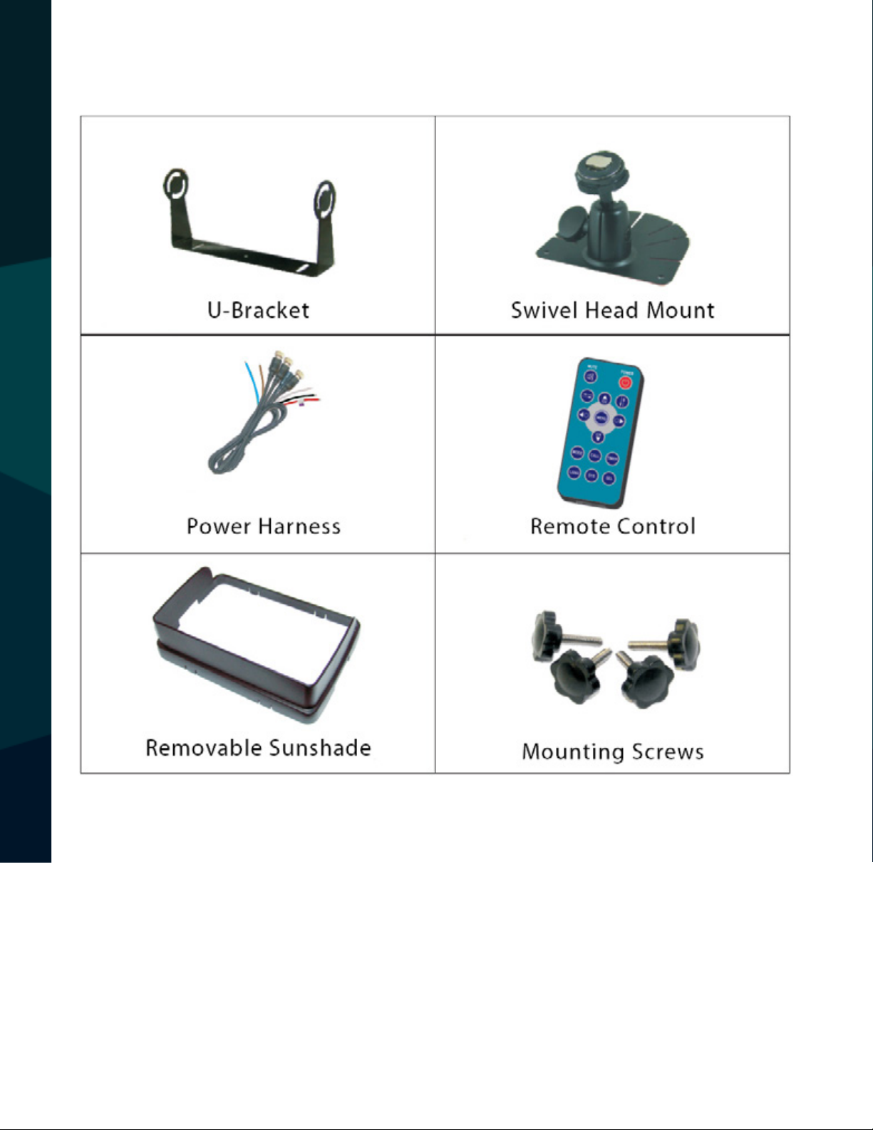
ACCESSORIES
FEATURES
10
Rear View Safety
Page 11

Product Features
1. 7” high resolution TFT LCD color monitor
2. Multiple image options (Horizontal/Vertical/Mirror/Normal)
3. Select from 8 languages
4. Automatic button backlighting and automatic brightness control
5. Full functional remote control
6. Multiple video formats (AUTO/PAL/NTSC)
7. 3 camera inputs
8. Power Inputs: DC / 10 - 32V (Supports 12V/24V ignition power source)
9. 3 trigger wires to automatically switch between backup/right/left
cameras
10. Automatic scanning function
11. Built-in speaker
12. Adjustable grid lines
FEATURES
Reverse With Condence ™
11
Page 12

Monitor Dimensions
MONITOR SPECIFICATION
1. 7” TFT LCD color monitor with a touch screen
2. Audio Output: 1.5W
3. Loudspeaker: One 15x24mm round speaker
4. Power Supply: 10-32V (ignition power source)
5. Power Consumption: ≈6W
6. Monitor Dimensions: 197.2mm (W) × 132mm (H) × 30.5mm (T)
7. Dot Pitch: 0.0642 (H) × 0.1790 (V)
8. Resolution: 800× 3 (RGB) × 480
9. Contrast: 500:1
10. Brightness: 400cd/m2
11. Viewing Angle: U: 50° / D: 70°, R/L: 70°/ 70°
12. Operating Temperature: -20~+70ºC, RH90%
13. Storage Temperature: -30~+80ºC, R 90%
14. Waterproof Rating: IP69K
12
Rear View Safety
Page 13

MONITOR INSTALLATION
Reverse With Condence ™
13
Page 14

Connections
WHITE / BLUE / BROWN 5 pin male for Camera 1 / Camera 2 / Camera 3. Connect
RED 12V power wire to an ignition power source, the BLACK 12V wire to a chassis
ground, the BROWN wire to reverse power, the WHITE wire to left turn signal
power and the BLUE wire to right turn signal power.
CONNECTIONS
14
Rear View Safety
Page 15

1. Sensor for remote signal
2. Power button
3. Increase / decrease the volume and switch sub-menu values
4. Move menu selection down
5. Menu button
6. Manual camera switch
MONITOR BUTTONS
Reverse With Condence ™
15
Page 16

Remote Operations
REMOTE OPERATIONS
16
MUTE: ENABLE/MUTE sound
POWER: Turn monitor on/o
: Flip image horizontally
Rear View Safety
Page 17

CH: : Flip image vertically
CH: Toggle selection up
CH: Toggle selection down
MENU: Access menu
MODE: Toggle picture modes (PERSONAL / STANDARD / SOFT /
VIVID / LIGHT)
: Decrease brightness
: Increase brightness
CALL: Display currrent video channel source
TIMER: Set a timer to shut down the monitor
(10 minute increments, 10-90 minutes)
LANG: Change languate
SYS: Toggle AUTO / PAL / NTSC.
SEL: Toggle camera channels
REMOTE OPERATIONS
Reverse With Condence ™
17
Page 18

Connection of AV Adapter and Controller Cable
Hold the cable , align the side of jack
marked with
connector with the male 13-pin connector
marked with
1. BROWN 5 pin male for Camera1
2. BLUE 5 pin male for Camera 2
3. WHITE 5 pin male for Camera 3
4. Connect RED 12V power wire to an ignition power source
5. BLACK 12V wire to a chassis ground
6. BROWN wire to reverse power
7. WHITE wire to left turn signal power
on the female 13-pin
then rmly connect
8. BLUE wire to right turn signal power
WIRING
18
Rear View Safety
Page 19

Reversing Display:
When the white wire is connected to left turn signal power, the monitor automatically switches to CAM1 (left side camera) when the left turn signal is activated.
Cam1
When the blue wire is connected to right turn signal power, the monitor automatically switches to CAM2 (right side camera) when the right turn signal is
activated.
Cam2
TRIGGER SETTING
Reverse With Condence ™
19
Page 20

When the BROWN wire is connected to reverse power, the monitor automatically switches to CAM 3 (backup camera) when the vehicle is put into reverse.
The distance grid lines will automatically display.
MENU AND TOUCHSCREEN OPERATIONS
AUTOSCAN: When ON, this setting allows the system to automatically switch
between connected camera inputs at a predetermined pace.
DISTANCE GRID LINES
20
Rear View Safety
Page 21

Menu
Press MENU 1-4 times to display the following options and settings:
1. PICTURE
2. OPTION
3. SYSTEM
4. AUTO SCAN
Picture
The PICTURE sub-menu inclues BRIGHT, CONTRAST, COLOR, VOLUME, AUTO DIM,
and SCALE ADJUST.
MENU
Reverse With Condence ™
21
Page 22

When AUTO DIM is ON in a dark environment, the on-screen display enters
dim mode. When AUTO DIM is turned ON or OFF in a bright environment, the
on-screen display remains the same.
MENU
Dim Mode
Normal Mode
22
Rear View Safety
Page 23

Press to select SCALE ADJUST (ability to adjust grid lines)
Reverse With Condence ™
MENU
23
Page 24

OPTION
The OPTION sub-menu includes LANG , SCALE , CAM1 , CAM2, and CAM3.
MENU
24
Rear View Safety
Page 25

SYSTEM
The SYSTEM sub-menu includes COLOR-SYS, BLUE BACK, HORIZONTAL, VERTICAL, and ZOOM.
MENU
Reverse With Condence ™
25
Page 26

AUTOSCAN
The AUTO SCAN sub-meun incldes AUTO SCAN, SCAN TIME, CAM1 , CAM2,
and CAM3
MENU
26
Rear View Safety
Page 27

Camera Dimensions
CAMERA DIMENSIONS
• 18 Infra-red illuminators (enables you to see in total darkness)
• 1/4 Sharp® color CCD, 250k pixels, 2.1 mm wide lens with 130° angle
• Shock resistant with a 20G Vibration and 100G impact rating
• Built-in high gain microphone
Reverse With Condence ™
27
Page 28

Camera Specications
SENSOR 1/4” SHARP® COLOR CCD
PICTURE ELEMENTS 250,000 PIXELS
GAMMA CORRECTION R=0.45 TO 1.0
IMAGE SENSOR 600 TV LINES, PAL: 500 H X 582 V
NTSC: 510 H X 492 V
LENS 2.1MM
VIEW ANGLE 130°
WATERPROOF RATING IP69K
SYNC SYSTEM INTERNAL SYNCHRONIZATION
INFRARED DISTANCE 50 FEET 18 INFRARED
USABLE ILLUMINATION 0 LUX IR ON
POWER SOURCE DC 12V24V +/ 10%
S/N RATIO MORE THAN 48DB
ELECTRONIC IRIS 1/50, 1601/100,000SEC
VIDEO OUTPUT 1VP P, 75
IR SWITCH CONTROL ACDS AUTOMATIC CONTROL
VIBRATION AND SHOCK RATING 20G / 100G
OPERATING TEMPERATURE 40°C ~ +80°C / RH 95% MAX
STORAGE TEMPERATURE 40°C ~ +60°C / RH 95% MAX
NET WEIGHT 22OZ
CAMERA SPECIFICATIONS
28
Rear View Safety
Page 29

Troubleshooting
Problem
No picture/sound Adaptor is connected incorrectly. Improper power supply. Unit is o.
No picture Check AV cable connection.
No sound
Dark picture
No color
Upside down/inverted picture
Audio cable improperly connected. Volume is o or set very low.
Adjust brightness/contrast. Low environmental temperature.
Adjust the color settings.
Use horizontal/vertical selection switch on remote control.
Possible Causes/Solutions
TROUBLESHOOTING
Reverse camera does not
display when car is in reverse
Check reverse connection
Reverse With Condence ™
29
Page 30

ONE YEAR WARRANTY
REAR VIEW SAFETY, INC. WARRANTS THIS PRODUCT AGAINST MATERIAL DEFECTS FOR A
PERIOD OF ONE YEAR FROM DATE OF PURCHASE. WE RESERVE THE RIGHT TO REPAIR OR
REPLACE ANY SUCH DEFECTIVE UNIT AT OUR SOLE DISCRETION. REAR VIEW SAFETY, INC.
IS NOT RESPONSIBLE FOR A DEFECT IN THE SYSTEM AS A RESULT OF MISUSE, IMPROPER
INSTALLATION, DAMAGE OR MISHANDLING OF THE ELECTRONIC COMPONENTS. REAR VIEW
SAFETY, INC. IS NOT RESPONSIBLE FOR CONSEQUENTIAL DAMAGES OF ANY KIND.
THIS WARRANTY IS VOID IF: DEFECTS IN MATERIALS OR WORKMANSHIP OR DAMAGES
RESULT FROM REPAIRS OR ALTERATIONS WHICH HAVE BEEN MADE OR ATTEMPTED BY
OTHERS OR THE UNAUTHORIZED USE OF NONCONFORMING PARTS; THE DAMAGE IS DUE
TO NORMAL WEAR AND TEAR, THIS DAMAGE IS DUE TO ABUSE, IMPROPER MAINTENANCE,
NEGLECT OR ACCIDENT; OR THE DAMAGE IS DUE TO USE OF THE REAR VIEW SAFETY, INC.
SYSTEM AFTER PARTIAL FAILURE OR USE WITH IMPROPER ACCESSORIES.
WARRANTY
WARRANTY PERFORMANCE
DURING THE ABOVE WARRANTY PERIOD, SHOULD YOUR REAR VIEW SAFETY PRODUCT
EXHIBIT A DEFECT IN MATERIAL OR WORKMANSHIP, SUCH DEFECT WILL BE REPAIRED WHEN
THE COMPLETE REAR VIEW SAFETY, INC. PRODUCT IS RETURNED, POSTAGE PREPAID AND
INSURED, TO REAR VIEW SAFETY, INC. OTHER THAN THE POSTAGE AND INSURANCE
REQUIREMENT, NO CHARGE WILL BE MADE FOR REPAIRS COVERED BY THIS WARRANTY.
WARRANTY DISCLAIMERS
NO WARRANTY, ORAL OR WRITTEN, EXPRESSED OR IMPLIED, OTHER THE ABOVE WARRANTY
IS MADE WITH REGARD TO THIS REAR VIEW SAFETY, INC. REAR VIEW SAFETY, INC. DISCLAIMS
ANY IMPLIED WARRANTY OR MERCHANTABILITY OR FITNESS FOR A PARTICULAR USE OR
PURPOSE AND ALL OTHER WARRANTIES IN NO EVENT SHALL REAR VIEW SAFETY. INC.
LIABLE FOR ANY INCIDENTAL, SPECIAL, CONSEQUENTIAL, OR PUNITIVE DAMAGES OR FOR
ANY COSTS, ATTORNEY FEES, EXPENSES, LOSSES OR DELAYS ALLEGED TO BE AS A
CONSEQUENCE OF ANY DAMAGE TO, FAILURE OF, OR DEFECT IN ANY PRODUCT INCLUDING,
BUT NOT LIMITED TO, ANY CLAIMS FOR LOSS OF PROFITS.
30
Rear View Safety
Page 31

DISCLAIMER
REAR VIEW SAFETY AND/OR ITS AFFILIATES DOES NOT GUARANTEE OR PROMISE THAT THE
USER OF OUR SYSTEMS WILL NOT BE IN/PART OF AN ACCIDENT OR OTHERWISE NOT COLLIDE
WITH AN OBJECT AND/OR PERSON. OUR SYSTEMS ARE NOT A SUBSTITUTE FOR CAREFUL
AND CAUTIOUS DRIVING OR FOR THE CONSISTENT ADHERENCE TO ALL APPLICABLE TRAFFIC
LAWS AND MOTOR VEHICLE SAFETY REGULATIONS. THE REAR VIEW SAFETY PRODUCTS ARE
NOT A SUBSTITUTE FOR REARVIEW MIRRORS OR FOR ANY OTHER MOTOR VEHICLE
EQUIPMENT MANDATED BY LAW. OUR CAMERA SYSTEMS HAVE A LIMITED FIELD OF VISION
AND DO NOT PROVIDE A COMPREHENSIVE VIEW OF THE REAR OR SIDE AREA OF THE VEHICLE.
ALWAYS MAKE SURE TO LOOK AROUND YOUR VEHICLE AND USE YOUR MIRRORS TO CONFIRM
REARWARD CLEARANCE AND THAT YOUR VEHICLE CAN MANEUVER SAFELY. REAR VIEW
SAFETY AND/OR ITS AFFILIATES SHALL HAVE NO RESPONSIBILITY OR LIABILITY
FOR DAMAGE AND/OR INJURY RESULTING FROM ACCIDENTS OCCURRING WITH VEHICLES
HAVING SOME OF REAR VIEW SAFETY PRODUCTS INSTALLED AND REAR VIEW SAFETY AND/
OR ITS AFFILIATES, THE MANUFACTURER, DISTRIBUTOR AND SELLER SHALL NOT BE LIABLE
FOR ANY INJURY, LOSS OR DAMAGE, INCIDENTAL OR CONSEQUENTIAL, ARISING OUT OF THE
USE OR INTENDED USE OF THE PRODUCT. IN NO EVENT SHALL REAR VIEW SAFETY AND/OR
ITS AFFILIATES HAVE ANY LIABILITY FOR ANY LOSSES WHETHER DIRECT OR INDIRECT, IN
CONTRACT, TORT OR OTHERWISE INCURRED IN CONNECTION WITH THE SYSTEMS,
INCLUDING BUT NOT LIMITED TO DAMAGED PROPERTY, PERSONAL INJURY AND/OR LOSS OF
LIFE. NEITHER SHALL REAR VIEW SAFETY AND/OR ITS AFFILIATES HAVE ANY
RESPONSIBILITY FOR ANY DECISION, ACTION OR INACTION TAKEN BY ANY PERSON IN
RELIANCE ON REAR VIEW SAFETY SYSTEMS, OR FOR ANY DELAYS, INACCURACIES AND/OR
ERRORS IN CONNECTION WITH OUR SYSTEMS FUNCTIONS.
DISCLAIMER
Reverse With Condence ™
31
Page 32

If you have any questions
about this product, contact:
Rear View Safety, Inc.
1797 Atlantic Avenue
Brooklyn, NY 11233
800.764.1028
Better Cameras. Better Service.
IT’S OUR GUARANTEE.
32
Rear View Safety
 Loading...