

Page 1
Product Manual
Installation Instructions
Rear View Camera Systems
Model # RVS-091407
© 2009-2013 Rear View Safety Inc.
Page 2

Table of Contents
Introduction ......................................................4
Safety Information .........................................5
Package Contents ............................................6
Settings/ Maintenance .....................................7
Installation Guide .............................................8
Positioning .....................................................11
Pairing and Connecting .................................12
Operation Guide .............................................12
LCD Parametres .............................................13
Monitor Dimensions ......................................14
Product Info ....................................................15
Warranty ........................................................17
3
Page 3

Introduction
Please read all of the installation instructions
carefully before installing the product. Improper
installation will void manufacturer’s warranty.
Congratulations on purchasing a Rear View Backup Camera
System. With this manual you will be able to properly install and
operate the unit.
The Backup Camera System is intended to be installed as a
supplement aid to your standard rear view mirror that already exists
in your vehicle. The Backup Camera System should not be used as
a substitute for the standard rear view mirror or for any other mirror
that exists in your vehicle
In some jurisdictions, it is unlawful for a person to drive a motor
vehicle equipped with a TV viewer or screen located forward of the
back of the driver’s seat or in any location that is visible, directly or
indirectly, to the driver while operating the vehicle.
4
Page 4

Safety Info
■
Place the monitor away from
■
The Rear View System
direct sun light, heat, water
or moisture.This product is
made with precise electronic
components. Handle with care.
Improper use can cause a
malfunction.
■
Firmly fi x the monitor stand to
secure location.
■
While installing the Rear View
System be careful with the wire
positioning in order to avoid
should only be used when
the vehicle is in reverse. Do
not watch movies or operate
the monitor while driving, It
may cause an accident.
■
Do not install the monitor
where it may obstruct drivers
view or obstruct an air bag
device.
■
Do not attempt to service this
product on your own. If the
system has any problem,
wire damage.
IN NO EVENT SHALL SELLER
OR MANUFACTURER BE
LIABLE FOR ANY DIRECT OR
CONSEQUENTIAL DAMAGES
OF ANY NATURE, OR LOSSES
OR EXPENSES RESULTING
FROM ANY DEFECTIVE
PRODUCT OR THE USE OF
ANY PRODUCT.
disconnect the power and
contact customer service.
■
Dropping the unit may
cause possible mechanical
failure.
If you have any questions
about this product, contact:
Customer Service:
Rear View Safety
1680 Atlantic Ave #301
Brooklyn, NY 11213
Tel: 800 764-1028
5
Page 5
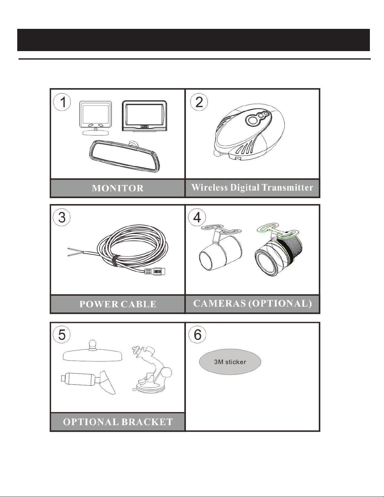
Package Contents
6
Page 6

Settings
You can adjust the contrast and brightness of the Monitor
according to your desired level.
Note: Contrast and Brightness setting ONLY works while the
backup image is on the screen.
1.To Adjust Contrast
Press the arrow key up or down
The system has 2 program functions:
1. Camera Setting
Push the Menu to pair, pairing mode will enable for 30 seconds
2. System setting
A.Power saving push menu to change the selection and hold the
Menu for long to exit
B. Brightness you can adjust the brightness of screen
C. Distance Grid, select grid line on/off
D. Default setting
Maintenance
Cleaning
• If dirt, rain or snow attaches to the camera, the monitor may
not clearly display objects.
• Do not use alcohol, benzene or thinner to clean the camera.
This will cause discoloration. To clean the
camera, wipe with a clean cloth dampened with mild cleaner
diluted with water and then wipe with a dry cloth.
7
Page 7

Installation Diagram
Diagram A
Dc female Dc male
BMW male BMW female
Diagram B
Fuse
DC12V
(Red)
GND
(Black)
Diagram C
DC12V
(Red)
GND
(Black)
Mounting the monitor:
The monitor either mounts on to, or replaces the existing rear view
mirror in your vehicle (see item options.)
The clip-on monitor uses
a special pressurized mechanism (see diagram A) which clips
onto the existing rear view mirror. To hard wire the monitor, (see
Diagram B) locate a 12V+- in your fuse box and make sure the
selected fuse is a ignition power source.
8
Page 8

Installation Guide
1.
Locate the reverse taillights wiring behind your reverse light.
You may need to remove the interior panel in order to locate.
You only need to attach the signal booster power wire to ONE
of the reverse lights, not both. If you cannot manually locate
the tail light cables, please contact the vehicle manufacturer or
reference a wiring diagram for your vehicle
At your taillight, remove the light bulb socket from the reverse
.
2
light housing.
Determine the reverse light power wires for your car, designating
3.
the positive and negative wires.
Connecting the Power Cables:
4.
Red wire to reverse light’s Positive wire. Connect the camera’s
Black Wire to reverse light’s Negative wire. (see Diagram C)
■ Place the fi xed adapter from the Wireless Digital
Transmitter Power Cable into the Wireless Digital Transmitter.
■ Determine the best place to mount the Transmitter. The
Transmitter is not waterproof and needs to be protected.
Determine the best route for the Camera Cable from the top of
5.
your license plate to the Transmitter. You may need to drill a
small hole in the panel behind where the license plate is situated.
9
Page 9

Installation Guide
Installation
6.
Plug the attached wire from the Camera into the Wireless
.
Transmitter. Ensure that the wires are not tangled.
7.
While sitting in the driver’s seat of the car with the key in the
ignition position. The monitor will automatically start when
vehicle is put in reverse. If when you place the vehicle in
reverse there is no image, you may need to pair the camera
with the monitor
8.
Put the vehicle in reverse. If you have a clear picture, put the
9.
10.
11.
vehicle back in park and turn the key to the off position. You are
now ready for fi nal stepshousing.
Take the Wireless Transmitter and using the double sided 3M
Sticker attach the box to the inside of your car.
Replace the light socket back into the reverse light housing.
Replace any interior panels that may have been removed to
access the taillight and close your trunk or
rear hatch.
10
Page 10

Positioning
11
Page 11

Pairing & Connecting
Pairing is not necessary as the unit has already been paired. If you
are not able to connect the camera, please try to pair the camera
by the following steps:
1. Press “Pair” button on the Wireless Digital Transmitter. You will
see the LED Blinking in RED/BLUE. The unit will
remain in Pair mode for 30 seconds
2. Go to the monitor and do the following step:
a. Press “Menu”
b. Go to “Pair Camera”
d. The unit is now in pair mode - if the unit was able to search and
connect with the camera, the
display will show “Pair OK”. If no camera is found, then the display
will show “Timed Out”.
Operation Guide
1. Power ON/OFF
• The Dash or Mirror Monitor will automatically turn ON when it is
connected to a power source, and the camera is recieving power.
2. Connection
• Rearview image will be automatically appear on the screen
during reverse and will remain in standby
when the vehicle is in any other gear or driving forward.”
12
Page 12

LCD Parametres
TFT LCD Digital Monitor
Screen Size 4.3"
Dot Resolution
Display Format 16:9
Display Brightness 400
Viewing Angle 90° Min
Video Input 1 channel
Video Source 1Vp-p, 75Ω
Power Supply DC 12V
Power Consumption 5W
Operating Temperature 10°C ~ +65° C
Video System Auto NTSC/PAL
800 X 3 (RGB) X480
Overall Dimensions 10” (L) x 3.5” (H) x 1” (D)
Weight 400G
Impact Rating 5G
Active Area 154.08(H) x 86.58 (V
Sync System Internal
13
Page 13

Monitor Dimensions
Display Image Size:
4.2
x 2.2
14
Page 14

Product Info
Camera MT9V136
Picture Elements 250,000 pixels
Gamma Correction r=0.45 to 1.0
Image Sensor
Lens 2.1mm
View Angle 130°
Sync System Internal Synchronization
Infra-red distance 30 Feet (9 Infrared IR)
Usable Illuminatiom 0 Lux (IR On)
Power Source DC 12V(+/- 10%)
S/N Ratio More than 48dB
Electronic Iris 1/50, 160-1/100,000sec
Video Output 1Vp.p 75ohm
480TV lines NTSC:510(H)*492(V)
IR Switch Control CDS Automatic Control
Impact Rating 10G
Operating Temperature -25°C - 50°C / RH 95% Max
Storage Temperature -25°C - 60°C / RH 95% Max
15
Page 15

Warranty
One Year Warranty
Rear View Safety Inc. warrants this product against material defects for a
period of one year from date of purchase. We reserve the right to repair
or replace any such defective unit at our sole discretion. Rear View Safety
Inc. is not responsible for a defect in the system as a result of misuse,
improper installation, damage or mis-handling of the electronic
components. Rear View Safety Inc. is not responsible for consequential
damages of any kind.
This warranty is void if: defects in materials or workmanship or damages result
from repairs or alterations which have been made or attempted by others or
the unauthorized use of nonconforming parts; the damage is due to normal
ware and tear, this damage is due to abuse, improper maintenance, neglect or
accident: or the damage is do to use of the Rear View Safety Inc. system after
partial failure or use with improper accessories.
Warranty Performance
DURING THE ABOVE WARRANTY PERIOD, SHOULD YOUR REAR
VIEW SAFETY PRODUCT EXHIBIT A DEFECT IN
MATERIAL OR WORKMANSHIP, SUCH DEFECT WILL BE REPAIRED
WHEN THE COMPLETE REAR VIEW SAFETY INC. PRODUCT IS
RETURNED, POSTAGE PREPAID AND INSURED, TO REAR VIEW
SAFETY INC. OTHER THAN THE POSTAGE AND INSURANCE REQUIREMENT, NO CHARGE WILL BE MADE FOR REPAIRS COVERED
BY THIS WARRANTY.
Warranty Disclaimers
NO WARRANTY, ORAL OR WRITTEN, EXPRESSED OR IMPLIED,
OTHER THE ABOVE WARRANTY IS MADE WITH REGARD TO THIS
REAR VIEW SAFETY INC. REAR VIEW SAFETY INC. DISCLAIMS ANY
IMPLIED WARRANTY OR MERCHANTABILITY OR FITNESS FOR A
PARTICULAR USE OR PURPOSE AND ALL OTHER WARRANTIES.
IN NO EVENT SHALL REAR VIEW SAFETY INC. LIABLE FOR ANY
INCIDENTAL, SPECIAL, CONSEQUENTIAL, OR PUNITIVE DAMAGES
OR FOR ANY COSTS, ATTORNEY FEES, EXPENSES, LOSSES OR
DELAYS ALLEGED TO BE AS A CONSEQUENCE OF ANY DAMAGE TO,
FAILURE OF, OR DEFECT IN ANY PRODUCT INCLUDING, BUT NOT
LIMITED TO, ANY CLAIMS FOR LOSS OF PROFITS.
Page 16

™
Rear View Safety, Inc.
1680 Atlantic Ave # 301
Brooklyn, N.Y. 11213
(800) 764-1028
www.rearviewsafety.com
 Loading...