


Table of Contents
Introduction...................................................................................................3
Safety Information .....
Before Beginning Installation.....
Installation Guide.....
Wiring Camera & Monitor.....
Replacement Installation Diagram.....
Clip-On Installation Diagram .....
Installing The Monitor.....
Monitor Operation .....
Splitting & Splicing .....
Positioning.....
Multiplexer .....
Monitor Dimensions.....
Monitor Specifications......
Troubleshooting.....
Warranty.....
Disclaimer .....
..............................................................................................16
.............................................................................................17
..................................................................................................21
...............................................................................................22
.............................................................................4-6
..............................................................7
....................................................................................8
..............................................................9-10
...................................................11
............................................................12
.........................................................................13
.............................................................................. 14
..............................................................................15
.............................................................................18
.......................................................................19
.....................................................................................20

Introduction
Please read all of the installation instructions
carefully before installing the product. Improper
installation will void manufacturer’s warranty.
Congratulations on purchasing a Rear View Backup Camera
System! With this manual you will be able to properly install and
operate the unit.
The Backup Camera System is intended to be installed as a
supplement aid to your standard rear view mirror that already ex-
ists in your vehicle. The Backup Camera System should not be
used as a substitute for the standard rear view mirror or for any
other mirror that exists in your vehicle.
In some jurisdictions, it is unlawful for a person to drive a
motor vehicle equipped with a TV viewer or screen located
forward of the back of the driver’s seat or in any location that is
visible, directly or indirectly, to the driver while operating the
vehicle.
3

Safety Information
Please read the entire manual and follow the instructions and
warnings carefully. Failure to do so can cause serious damage
and/or injury, including loss of life. Be sure to obey all applicable local traffic and motor vehicle regulations as it pertains to
this product. Improper installation will void manufacturer’s
warranty.
USAGE
• The Rear View Camera System
is designed to help the driver
safely detect people and/or
objects helping to avoid
damage or injury. However,
you the driver, must use it
properly. Use of this system is
not a substitute for safe,
proper or legal driving.
• Never back up while looking
at the monitor alone. You
should always check behind
and around the vehicle when
backing up, in the same way
as you would if the vehicle
did not have the Rear View
4
Camera System. If you back
up while looking only at the
monitor, you may cause
damage or injury. Always
back up slowly.
• The Rear View Camera Sys-
tem is not intended for use
during exstensive back-up
maneuvers or backing into
cross traffic or pedestrian
walkways.
• Please, always remember,
the area displayed by the
Rear View Camera System is
limited. It does not display
the entire panorama that is
behind you.
REAR VIEW SAFETY

Safety Information
INSTALLATION
• Electric shock or product
malfunction may occur if
this product is installed
incorrectly.
• Use this product within
the voltage range specified.
Failure to do so can cause
electronic shock or product
malfunction.
• Take special care when
cleaning the monitor.
• Make sure to firmly affix the
product before use.
• If smoke or a burning smell
is detected, disconnect the
system immediately.
• Where the power cable may
touch a metal case, cover the
cable with a friction tape. A
short circuit or disconnected
wire may cause a fire.
• While installing the RVS
System be careful with the
wire positioning in order to
avoid wire damage.
• The RVS System should only
be used when the
vehicle is in reverse.
• Do not watch movies or
operate the monitor while
driving; as it may cause an
accident.
• Do not install the monitor
where it may obstruct drivers
view or obstruct an air bag
device.
• Dropping the unit may cause
possible mechanical failure.
Reverse With Confidence
™
5
Safety Information
If you have questions about this product, contact:
Customer Service:
Rear View Safety
1797 Atlantic Avenue
Brooklyn, NY 11233
Tel: 1.800.764.1028
IN NO EVENT SHALL SELLER OR MANUFACTURER BE
LIABLE FOR ANY DIRECT OR CONSEQUENTIAL DAMAGES OF
ANY NATURE, OR LOSSES OR EXPENSES RESULTING FROM
ANY DEFECTIVE PRODUCT OR THE USE OF ANY PRODUCT.
6
REAR VIEW SAFETY

Before You Begin Installation
Before drilling please check that no cable or wiring is on the
other side of the wall. Please clamp all wires securely to reduce
the possibility of them being damaged while vehicle is in use.
Keep all cables away from hot or moving parts and electrical
noisy components.
We recommend doing a benchmark test before installation
to insure that all components are working properly.
Step 1: Choose the monitor and camera locations.
Step 2: Install all cables in vehicle, when necessary a 0.8 (20mm)
hole should be drilled for passing camera cable through vehicles
walls. Install split grommets where applicable.
Step 3: Once all cables and wiring have been properly routed,
perform a system function test by temporarily connecting the
system. If the system seems to not be operating properly see
troubleshooting (page 20).
Reverse With Confidence
™
7

Installation Guide
Cable
1. Be sure to position the cable properly. The aviation camera
cable uses aircraft grade connectors which means the camera
cable can be exposed to all weather elements. Do not run the
cable over sharp edges, do not kink the cable and keep away
from HOT and rotating parts.
2. Fasten all cables and secure all excess cable.
Replacement Monitor
1. The Mirror Monitor replaces the existing rear view mirror in
vehicle.
2. Replace existing mirror, and adjust mounting angle to allow
optimum driver viewing comfort. (see figure 1.1 on page 11).
Clip-On Monitor
1. The Mirror Monitor attaches to the existing rear view mirror in
vehicle with the pressurized clips on the back of the monitor.
2. Attach monitor to existing miror, and adjust mounting angle to
allow optimum driver viewing comfort. (see figure 1.1 on page
12).
8
REAR VIEW SAFETY

Wiring Camera & Monitor
The multiplexer.
• To power the system connect
the power (RED) 12V+ wire to
ignition power and the ground
(BLACK) wire to chassis ground.
• These are the only wires
needed to power the entire
system and all the cameras.
Each camera can be seen at
any time by simply pressing
the power button and using
the V1/2 button to toggle.
• The three positive trigger wires
(BLUE-CH1, WHITE-CH2,
YELLOW-CH3) each represent
one channel and will turn on
their channel when the trigger
wire is energized with 12V.
• "Camera 3" is the designated
backup channel. To have the
the backup camera come on
when you go into reverse, connect the BLUE wire to reverse
power (or any power source
that comes on only in reverse).
• The other channels can simi-
larly be triggered (i.e. side cameras can be triggered by the turn
signals etc.)
• To automatically have camera
and monitor turn ON when vehicle activates, simply twist BLUE
positive trigger 12V+ to Red
Power line 12V+ and wire to ignition power.
Note: This setup will disable
the menu in channel 3. To
access the menu simply move
to channel 1 or 2 and all the
changes will apply to channel
3.
Note: When the blue wire is
active it will have precedence
over the other triggers.
Therefore, if you wish to use
multiple triggers, do not
attach the blue trigger to
constant power.
Reverse With Confidence
™
9

Wiring Camera & Monitor
• Audio: There is audio on
channels 2 and 3. On channel 3
the blue trigger wire must be
energized (12V) to activate the
audio. On channel 2 the audio
is always on.
• Grid-lines: The grid-lines are
also carried through the blue
wire. To use the grid-lines for
reversing, connect the blue
wire to a reverse power.
Note: The camera and
monitorcan always be
activated by manually
pushing the power button on
monitor. This is in addition to
utilizing the positive triggers.
• There is a built-in voltage
regulator for our systems which
can handle 12-24 volts. Real
consumption is 10 to 30 Volts.
Note: If connecting power
directly to battery, the camera
is always ON and therefore can
drain battery. Therefore it is
recommended to connect
power to an ignition switched
accessory power source.
10
REAR VIEW SAFETY

Replacement Installation Diagram
Replacement Monitor
Figure 1.1 Figure 1.2
Figure 1.3
Reverse With Confidence
™
11
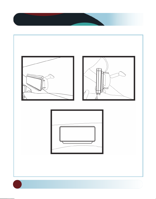
Clip-On Installation Diagram
Clip-On Monitor
Figure 1.1 Figure 1.2
Figure 1.3
12
REAR VIEW SAFETY
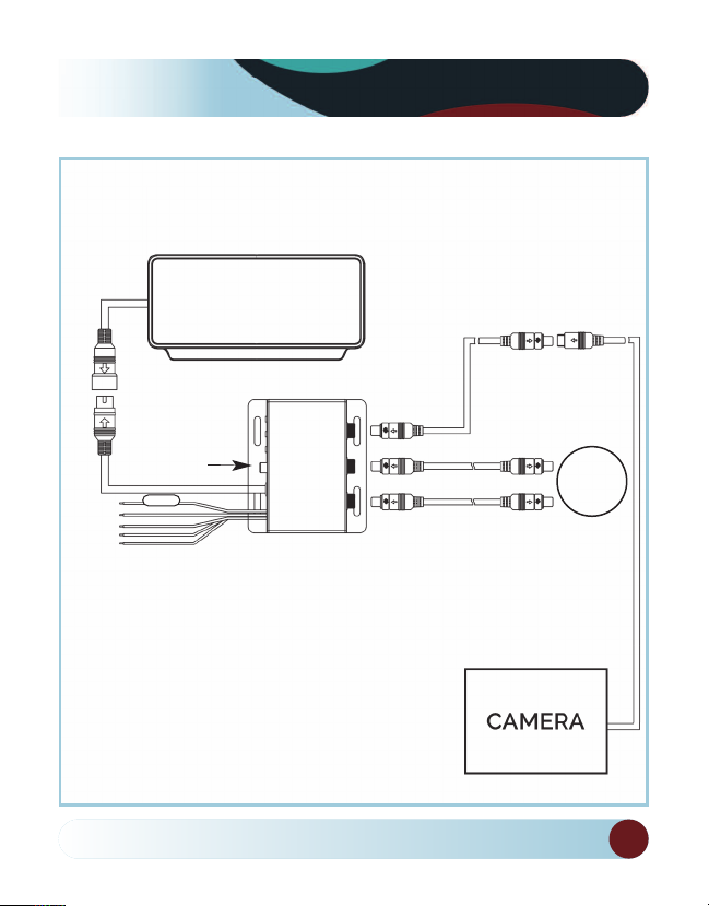
Monitor
Installing the Monitor
66ft Extension Cable
Video Out
1
-3 Amp Fuse
2
3
4
5
1. DC12V-24V (red)
2. Ground (black)
3. Port #3 (blue)
4. Port #2 (white)
5. Port #1 (yellow)
Reverse With Confidence
Optional
Camera
Multiplexer
™
Available
13

Monitor Operation
!!
!!
!!
!!
!!
• Brightness, Contrast, Saturation, Sharpness: Adjust image properties
• Picture Adjust: Stretch image horizontally (right/left and left/right)
• Turn: Toggle between mirror/normal image on each individual channel
• Name: Change name of teach individual channel
• Trigger Delay: Adjust time delay on each trigger
• Trigger Source: Toggle channel destination for each trigger
• Distance Grid: Toggle which channel distance grid lines will display on
• Grid Position: Adjust position of distance grid lines
• Auto Power: On: Monitor will automatically turn on when powered. Off: Monitor
will only turn on when triggered. Auto: Monitor will follow previous state.
• Reset: Reset settings to factory default
14
REAR VIEW SAFETY
UP
MENU
DOWN
V1/V2
ON/OFF

Splicing
1.
2.
3.
4.
5.
1. Red - Power (+)
2. Yellow - Video
3. Green - Mirror / Normal Imaging
4. White - Audio
5. Black - Ground (-)
Reverse With Confidence
™
15

Positioning
General Installation Location
16
REAR VIEW SAFETY

(select cameras only)
Multiplexer
Reverse With Confidence
Port #1 Port #2 Port #3
™
or DVD Backup
17

Monitor Dimensions
Clip-On MonitorReplacement Monitor
18
REAR VIEW SAFETY

Monitor Specifications
TFT LCD Digital Monitor
Screen Size Digital 7”
Dot Resolution 800
H x 3 (RGB) x 480V
Display Format 16:9
Display Brightness 400cd/m
Viewing Angle 90° min
Video Input 3 channel
Video Source 1Vp-p, 75Ω
Power Supply DC 12V-24V (+/-10%)
Power Consumption 5W
Operating Temperature -10°C - +65° C
Video System Auto NTSC/PAL
Overall Dimensions 9”
L x 4.5”H x 1”D
Weight 400G
Impact Rating 5G
Dot Pitch 0.192
H x 0.1805V
Sync System Internal
Reverse With Confidence
™
2
19

Troubleshooting
Monitor Displays Blue Screen & Displays No Signal
• Do a hard reset, unplug all
cables and power cables from
multiplexer (silver box) leave
out for 1 minute and then
re-connect them.
• Check to ensure that the con-
nection to the camera is tight.
• Verify camera cable is plugged
into port labeled Backup Camera
• Verify that the blue positive
trigger on power harness is
put to power 12v+.
If the problem still persists, verify that alternate ports work. If
alternate ports do not work, remove Blue Trigger wire from
12V+ and select alternate channels.
Monitor Will Not Power-Up (no backlight on power button)
• Check fuse
• Check 12v+ to monitor
• Check ground connection
No Image On Screen
• Verify camera is in correct
camera input
• Verify cable is connected to
monitor
• Verify camera is connected to
cable
• Connect known working
camera and cable to monitor.
• Verify Blue trigger is receiving
power
Audio on Camera (optional)
• Verify chosen camera has audio
• Verify volume setting
20
• Confirm that the Blue audio
trigger is connected to 12v+
REAR VIEW SAFETY

Warranty
One Year Warranty
Rear View Safety Inc. warrants this product against material defects
for a period of one year from date of purchase. We reserve the right
to repair or replace any such defective unit at our sole discretion.
Rear View Safety Inc. is not responsible for a defect in the system as
a result of misuse, improper installation, damage or mis-handling of
the electronic components. Rear View Safety Inc. is not responsible
for consequential damages of any kind.
This warranty is void if: defects in materials or workmanship or damages result from
repairs or alterations which have been made or attempted by others or the unauthorized use of nonconforming parts; the damage is due to normalware and tear, this
damage is due to abuse, improper maintenance, neglect or accident: or the damage is
do to use of the Rear View Safety Inc. system after partial failure or use with improper accessories.
Warranty Performance
DURING THE ABOVE WARRANTY PERIOD, SHOULD YOUR REAR VIEW SAFETY
PRODUCT EXHIBIT A DEFECT IN MATERIAL OR WORKMANSHIP, SUCH DEFECT
WILL BE REPAIRED WHEN THE COMPLETE REAR VIEW SAFETY INC. PRODUCT
IS RETURNED, POSTAGE PREPAID AND INSURED, TO REAR VIEW SAFETY INC.
OTHER THAN THE POSTAGE AND INSURANCE REQUIREMENT, NO CHARGE
WILL BE MADE FOR REPAIRS COVERED BY THIS WARRANTY.
Warranty Disclaimers
NO WARRANTY, ORAL OR WRITTEN, EXPRESSED OR IMPLIED, OTHER THE
ABOVE WARRANTY IS MADE WITH REGARD TO THIS REAR VIEW SAFETY INC.
REAR VIEW SAFETY INC. DISCLAIMS ANY IMPLIED WARRANTY OR MERCHANTABILITY OR FITNESS FOR A PARTICULAR USE OR PURPOSE AND ALL OTHER
WARRANTIES IN NO EVENT SHALL REAR VIEW SAFETY INC. LIABLE FOR ANY
INCIDENTAL, SPECIAL, CONSEQUENTIAL, OR PUNITIVE DAMAGES OR FOR ANY
COSTS, ATTORNEY FEES, EXPENSES, LOSSES OR DELAYS ALLEGED TO BE AS A
CONSEQUENCE OF ANY DAMAGE TO, FAILURE OF, OR DEFECT IN ANY PRODUCT INCLUDING, BUT NOT LIMITED TO, ANY CLAIMS FOR LOSS OF PROFITS
Reverse With Confidence
™
21

Disclaimer
Rear View Safety and/or its affiliates does not guarantee or promise
that the user of our systems will not be in/part of an accident or
otherwise not collide with an object and/or person. Our systems are
not a substitute for careful and cautious driving or for the consistent
adherence to all applicable traffic laws and motor vehicle safety
regulations. The Rear View Safety products are not a substitute for
rearview mirrors or for any other motor vehicle equipment mandated
by law. Our camera systems have a limited field of vision and do not
provide a comprehensive view of the rear or side area of the vehicle.
Always make sure to look around your vehicle and use your mirrors
to confirm rearward clearance and that your vehicle can maneuver
safely. Rear View Safety and/or its affiliates shall have no responsibility or liability for damage and/or injury resulting from accidents
occurring with vehicles having some of Rear View Safety products
installed and Rear View Safety and/or its affiliates, the manufacturer,
distributor and seller shall not be liable for any injury, loss or
damage, incidental or consequential, arising out of the use or
intended use of the product. In no event shall Rear View Safety
and/or its affiliates have any liability for any losses (whether direct
or indirect, in contract, tort or otherwise) incurred in connection
with the systems, including but not limited to damaged property,
personal injury and/or loss of life. Neither shall Rear View Safety
and/or its affiliates have any responsibility for any decision, action
or inaction taken by any person in reliance on Rear View Safety
systems, or for any delays, inaccuracies and/or errors in connection
with our systems functions.
22
REAR VIEW SAFETY

Take Notes
Reverse With Confidence
™
23

If you have any questions
about this product, contact:
Rear View Safety, Inc.
1797 Atlantic Avenue
Brooklyn, NY 11233
800.764.1028
BETTER CAMERAS. BETTER SERVICE.
IT’S OUR GUARANTEE.
 Loading...