

Page 1
Roadscope7 Install Guide
RoadScope 7
Installation Manual
Page 2

Roadscope7 Install Guide
Table of Contents
1. Precautions
1.1 General
1.2 System Limitation
1.3 Installation and Safety Precautions
2. System Structure
2.1 System Description
2.2 Hub Connection Diagram
2.3 Vehicle Wire Pin map
2.4 R7 manager
3. Installation
3.1 Installation Procedures
3.2 Installation in detail
3.3 Vehicle Pulse Input
3.4 Calibration
4. Main Body
4.1 Functions & Names
4.2 Button Operation
4.3 LED Description
5. Display device Description
5.1 Functions & Names
5.2 Button operation
5.3 Graphic description
6. Diagnosis
6.1 Check Errors
7. Repair Service
8. Specification
Page 3

Roadscope7 Install Guide
1. Precautions
1.1 General
Please carefully read following "Notes" below before attempting to install Roadscope 7.
Roadscope 7 is an Advanced Driver Assistance System aiming to alert the driver to potential risky collisions. Roadscope
7 does not replace the responsibility and duty of the driver to remain focused on the road at all times , driver is solely
responsible for accidents caused by driver’s negligence.
Roadscope 7 cannot and does not guarantee 100% accuracy in the detection of front vehicles, driving lanes, pedestrians
or traffic signs. The detection rate can be adversely affected by extremely bad weather, road and other abnormal
conditions.
Drivers should concentrate on forward-looking while driving by paying full attention to safe driving.
* Roadscope 7 is designed to assist in careful driving , however, it is not a substitute for careful driving practices and the
manufacturer of Raodscope 7 takes no responsibility for any damage caused by reckless driving behavior.
Precautions
Page 4

Roadscope7 Install Guide
1. Precautions
1.2 System Limitation
If the view of camera is blocked partially or completely, the functionality may be adversely affected or may not work.
Lane Departure Warning 【LDW】 performance can be affected adversely if lanes are poorly marked or unmarked.
Front vehicle detection 【 HMW, FCW, VB and FCDA 】 performance can be affected adversely if rear lamps of a front
vehicle are in abnormal conditions 【broken or low light】 at night.
Traffic Sign Recognition 【TSR】 performance can be affected adversely if traffic signs are severely tilted or
decolorized.
Pedestrian Detection 【PD】 and Traffic Sign Recognition 【TSR】 do not work at low illuminance or at night .
Each ADAS function remains active at or above the set start speed threshold .
ADAS Setting ranges are shown as below
Sensitivity setting: * marked parts can be set in R7 manager PC program and ** marked parts can be set in the display
device.
Roadscope 7 does not output another same-type alarm for 5 seconds after an alarm is generated ( except FCW )
Function LDW HMW FCW VB PD FCDA TSR
Setting
Range
40~80kph
25~50mph
20~80kph
12~50mph
- - - - -
Operational
Speed
Above the set start
speed threshold
Above the set start
speed threshold
Over1kph
Over 1mph
1~20kph
1~12mph
5~30kph
3~18mph
0kph
0mph
Over1kph
Over 1mph
Sensitivity
setting*
O O - O - O -
Sensitivity
setting **
O O - - - - -
Page 5

Roadscope7 Install Guide
1. Precautions
1.3 Installation and Safety Precautions
Roadscope7 must be installed using the appropriate tools by professional technicians
Install Roadscope7 when parked on a flat surface with vehicle power supply at OFF 【Wiring connections】
Roadscope7 should be operated with only 12 ~ 24v power supply.
Be careful not to have the camera coated with contaminated materials and pay attention to proper camera angle while
installing .
After installation, change settings in accordance with the Installation guide.
Do not connect or disconnect any cable if vehicle engine is ON.
Roadscope 7 does not guarantee 100% accuracy in the detection of front vehicles, driving lanes, pedestrians and traffic
signs. The detection rate can be adversely affected by extremely bad weather, road and other abnormal conditions.
If not installed according to this manual instruction , R7 may not work properly .
Page 6

Roadscope7 Install Guide
2. System Structure
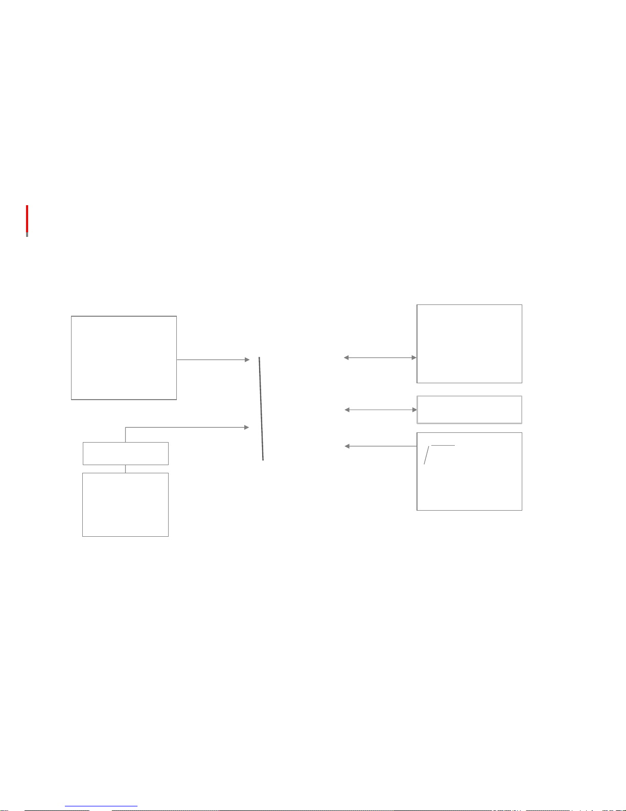
2.1 System Description
Roadscope7 Main Body System
Display Device
Hub [ part name: dual hub ]
Vehicle connection cable
Setup software Program 【 R7 manager program will be provided by the manufacturer separately 】
Please check following parts before installation
① Roadscope7 main body system :
main body with Hub connection Cable
② Display Device:
Indication of detection info , warnings and sensitivity settings
Page 7

Roadscope7 Install Guide
2. System Structure
2.1 System Description
④ Vehicle Cable : Vehicle power supply and signal input cable
⑤ R7 manager : Setup Software 【 provided separately
by the manufacturer】
③ Hub : Main body , display device , vibrator 【option】 ,
vehicle power & signal input
⑥ Manager Program Connection Cable
【 the quantity should be negotiated with the manufacturer
separately 】
Page 8
Roadscope7 Install Guide
2. System Structure
2.2 Hub Connection Diagram
3G device, Tacho
etc.,
RS232
UART
Power & Vehicle Signal
Option
Option
Page 9

Roadscope7 Install Guide
2. System Structure
2.3 Hub to Vehicle Cable - Pin Map
No. Name
Wire
Color
Description Recommend
1 IG【ACC】 Red
IG
2【Key-On】 power
Vehicle
Signal
3 BRAKE Brown
Brake
signal
Vehicle
Signal
7 TURN_R Yellow
Right
turn signal
a
. Vehicle Signal
b
. CAN Signal
8 TURN_L White
Left
turn signal
9 VSS Blue
Speed
signal
a.
Vehicle Signal
b
. CAN Signal
10 GND Black
Ground
signal
Vehicle
Signal
2.3.1 Basic Connection
No. Name Wire Color
Description Recommend
2 B+ Violet B+
not
connect
4 WIPER Green
Wiper
signal
High
speed
5 CAN_High Orange
CAN
【High】Connection
Contact
manufacturer
6 CAN_Low Gray
CAN
【Low】 Connection
2.3.2 Optional Connection
• If TURN wires are not connected, LDW function will generate warnings every time the driver
changes driving lanes even with blinkers turned on
• Wiper needs to be connected to High-speed wiper signal if available.
• Roadscope7 can use CAN signal communication method to receive vehicle CAN
signals ,such as TURN , SPEED and BRAKE . For the CAN connection, please consult with
manufacturer of R7 .
Page 10

Roadscope7 Install Guide
2. Roadscope 7 manager
How to Install
- Install the driver and manager software programs which are provided by your dealer or
manufacturer, in your laptop PC
How to install the driver
- The driver file should be installed based on your OS spec . Please install accordingly
- 32bit : CP210 x VCPinstaller_x86
- 64bit : CP210 x VCPinstaller_x64
Manager Function
① Camera calibration
② Product setting
③ Real-time camera image check and image saving
④ Check error code
⑤ Check program version information
Manager Connection
- Connect Roadscope 7 to R7 manager program by pressing the 'Connect' button【 】.
Recommended OS
- Window7/8/8.1/10【32/64bit】
2.4 R7 manager
Page 11
Roadscope7 Install Guide
3. Installation
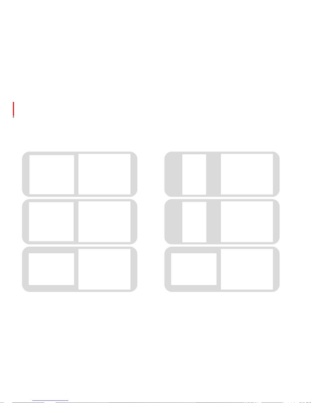
3.1 Installation in brief [ please refer to 3.2 for detailed installation methods ]
1.Separate the cover of
Roadscope 7
4. Connect to R7
manager to finish setup
5. Calibrate camera
angle via R7 manager
program
6. Test drive on the
road to check if speed
signal and warnings
work properly
3. Connect Roadscope
7 cable to Hub, and
connect vehicle cable
to Hub
2. Attach Roadscope 7
to the windshield
Page 12
Roadscope7 Install Guide
3. Installation
3.2 Installation in detail
Installation & Precautions
install the product when parked on the flat ground
connect the product when vehicle power is turned off
wipe out if dirt is attached to the main body camera
ensure to attach to the windshield area which is not highly humid
do not touch the adhesive side of tape with your hands .it may
deteriorate the adhesive strength.
install R7 in the place where it does not interfere with driver’s sight
install R7 in parallel to the flat ground
R7 is recommended to be installed at the center of windshield , if not
possible, the offset distance from center should not be bigger than 20cm
Recommended install position
Camera offset【center=0cm】
BUS Truck
① Pull the Cap cover downwards to separate
② To separate the upper cover ,please loosen side screws and keep
unlocked screws in a safe place to avoid losing them
④ Clean the front windshield and install the product, please ensure to
firmly attach body tape to the windshield by pressing the main body
manually, but without giving pressure on PCB board
③A buzzer is attached to the upper cover . First, separate the connector, then
separate the cover
Page 13

Roadscope7 Install Guide
3. Installation
3.2 Installation in detail 【System Installation】
Install-caution
please ensure to place the display device on the dashboard arear
where it does not interfere with driver sight
First, connect main body and display device to Hub,
Then ,connect the vehicle signal cable to Hub
Default Connection Optional Connection
No Wire Color No Wire Color
1 IG Red 4 Wiper【High】 Green
3 BRAKE Brown 5 CAN_High Orange
7 TURN_R Yellow 6 CAN_Low Grey
8 TURN_L White
9 SPEED Blue
10 GND Black
If you do not know the pulse value of vehicle, it can be
automatically set by pressing the button on the display device
while driving.
If the turn signal is not connected , LDW function will generate
warning signal every time driver changes driving lanes even with
the blinker light turned on .
For the CAN connection method, a separate prior consultation is
required depending on the car model.
① ②
③
• Connect the cables by following the diagram sequence above
1. Connect main body and display device to Hub
2. Connect vehicle cable to Hub thereafter
Page 14

Roadscope7 Install Guide
3. Installation
3.2 Installation in detail 【Manager Program Connection】
Installation & Precautions
The setup process will take around 5 to 10 minutes . Check if
the remaining battery power of your laptop is enough before
attempting to install .
① Connect the configuration cable to the connector of main body
② Connect the configuration cable to your laptop PC ,
afterwards , run the manager program ,
When the program start screen appears ,click [connect] button to check if LED
light of cable turns on.
If there is no LED light, you may need to install R7 driver in your PC OS.
[ Refer to page 11 for R7 driver installation procedures ]
③ First, check if the manager program is connected to R7,
then, check if vehicle cable is connected properly
A. When pressing the brake pedal , the brake icon will indicate in the manager program
B. Turn on the left blinker to see if the left arrow icon turns on
C. Turn on the right blinker to see if the right arrow icon turns on
D. Drive slowly to see if the speed data reading works properly
LED
Page 15

Roadscope7 Install Guide
3. Installation
3.2 Installation in detail 【Angle Adjustment】
Adjust the angle of the
camera by following the
red arrow direction.
Install-caution
Tighten screws until the camera angle does not turn further.
If not fastened enough, the camera angle can be changeable when driving over speed bumps or receiving routine impacts.
If the camera angle is not calibrated well , it can cause detection failures or false alarms.
If the word 'Calibration' in the middle of the
Manager window turns green, firmly fasten the
camera .
Press the 'Calibration'
button of R7 manager.
After fastening the camera , exit calibration
mode by pressing the 'Calibration' button.
Page 16

Roadscope7 Install Guide
3. Installation
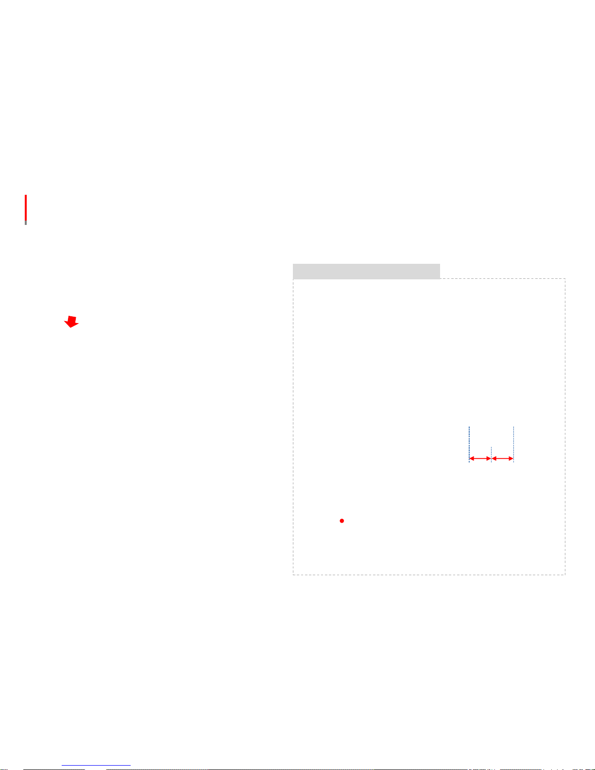
3.2 Installation in detail 【Install Setting】
Press the 'Setting' button
of R7 manager.
Camera
Height
Car Width
Hood Length
Camera offset
【Center=0mm】
Choose the install position
and input accordingly
⑤~⑦ Select the appropriate signal type of
Turn / Brake / Wiper signals.
⑧ Enter the speed pulse value of the vehicle.
If not known, set the value manually by
referring to page 29.
① ②
③
④
⑤
⑥
⑦
⑧
①
② ③
④
Page 17

Roadscope7 Install Guide
3. Installation
3.2 Installation in detail 【General Setting】
① set the alarm ON / OFF.
② adjust the volume of the alarm.
③ set the Display ON / OFF.
④ set the Vibrator ON / OFF.
⑤ set the Display button operation ON / OFF.
⑥ set the body button operation ON / OFF.
①
②
③
④
⑤
⑥
Page 18

Roadscope7 Install Guide
3. Installation
3.2 Installation in detail 【LDW Setting】
① set the LDW alarm ON / OFF.
② set LDW function start speed.
③ set the LDW sensitivity of left and right
respectively. 【 If input value is smaller, the
function will become less responsive 】
①
②
③
Page 19

Roadscope7 Install Guide
3. Installation
3.2 Installation in detail 【FCW Setting】
① set the FCW alarm ON / OFF.
①
Page 20

Roadscope7 Install Guide
3. Installation
3.2 Installation in detail 【HMW Setting】
① set the HMW alarm ON / OFF.
② set the HMW function start speed.
③ set the HMW function sensitivity. 【 If input
value is smaller, the function will become less
responsive 】
①
②
③
Page 21

Roadscope7 Install Guide
3. Installation
3.2 Installation in detail 【FCDA Setting】
① set the FCDA alarm ON / OFF
② set the responsiveness of FCDA notice
after the movement of front car
- 0 sec: inform immediately if the
movement of a front car is detected
- 1 sec: inform with 1 second delay if the
movement of a front car is detected
①
②
Page 22

Roadscope7 Install Guide
3. Installation
3.2 Installation in detail 【VB Setting】
① set the VB alarm ON / OFF.
② set the VB alarm sensitivity.
【 If input value is smaller, the function will
become less responsive 】
①
②
Page 23

Roadscope7 Install Guide
3. Installation
3.2 Installation in detail 【TSR Setting】
① set the TSR alarm ON / OFF
①
Page 24

Roadscope7 Install Guide
3. Installation
3.2 Installation in detail 【PD Setting】
① set the PD alarm ON / OFF
② set the PD alarm sensitivity.
【 If input value is smaller, the function will
become less responsive 】
①
②
Page 25

Roadscope7 Install Guide
3. Installation
3.2 Installation in detail 【Check Images & Save】
Press the 'Camera
Image' button of R7
manager.
① ②
① If the 'Camera Image' button is pressed,
what camera sees will appear in the middle of
R7 manager
② If the 'Image Save' button is pressed, what
camera sees will be saved as jpg files. The
images will be saved in the designated path
selected by user. In order to pause image
saving process, just press the 'Image save'
button again
③ After finishing the image saving process ,
press the 'Camera Image' button to exit the
mode
Page 26

Roadscope7 Install Guide
3. Installation
3.2 Installation in detail 【Check Information】
① Press 'Info' button to check following
information
- Roadscope7 Serial number
- Error code
- F/W version
- R7 Manager version
Page 27

Roadscope7 Install Guide
3. Installation
3.2 Installation in detail 【Check while driving 】
Install-caution
It is recommended to check system operation while driving in order
to confirm the correct installation settings of Roadscope 7.
If R7 manager program is connected, you can check whether the
speed input is being received correctly and you can also adjust the
sensitivity for each function.
It is important to have a person on the passenger seat to monitor
system operation . Careless driving will cause accidents.
Page 28

Roadscope7 Install Guide
3. Installation
3.3 Vehicle Pulse Input
The speed wire of vehicle can output pulse signal which is in proportion to actual driving speed.
Roadscope 7 can calculate and apply the pulse value during driving even if the vehicle pulse value is unknown.
As Roadscope 7 calculates driving speed with the interval of 1 second by detecting the number of pulses, it is not affected by
wheel diameter of tire or gear ratio, etc.
How to Input Pulse
Press and hold button ③ of main body for over 3 seconds and release the
button when driving speed reaches 60 km/h 【37mph】, R7 can
automatically calculate the pulse value.
Keep the driving speed at 60 km/h 【37mph】 for over 10 seconds on the flat
road to enable correct system calculation.
Press and hold button ③ of display device for 3 seconds and release the
button when driving speed reaches 60 km/h 【37mph】, R7 can
automatically calculate the pulse value.
Keep the driving speed at 60 km/h 【37mph】 for over 10 seconds on the flat
road for the correct system calculation.
Note that driver attention should remain focused on the road at all times and driver should not operate R7 or display
device while driving. It is necessary to have a person on passenger seat to operate the system instead in order to prevent
possible accidents that could be caused by driver inattention .
Caution
③
③
Page 29

Roadscope7 Install Guide
3. Installation
3.4 Calibration
The vanishing point calibration will be implemented to optimize system performance of Roadscope 7
Automatic calibration
- When driving speed reaches 70 km/h 【43 mph】 after initial installation, it will automatically calibrate by understanding the
driving condition.
Manual calibration
- If alarm timing accuracy is not ideal , user can start manual calibration to correct the vanishing point.
- Manual calibration should be done when lanes are clearly visible on flat & straight road.
How to calibrate manually
When LED of main body is Green , Press and hold button ① on the main
body for more than 3 seconds before driving on the road.
When driving speed reaches 70 km/h , the system will calibrate by itself if the
driving condition is appropriate for calibration. 【 Driving on the flat road for
30 seconds 】
When LED of display device is Green , Press and hold button ① on the
display device for more than 3 seconds before driving on the road.
When driving speed reaches 70 km/h , the system will calibrate by itself if the
driving condition is appropriate for calibration . 【 Driving on the flat road for
30 seconds 】
.
ADAS functions are active during calibration process.
Do not operate buttons while driving. Driver inattention may cause accidents.
Caution
①
①
Page 30

Roadscope7 Install Guide
4. Main Body Description
4.1 Functions & Names
Camera
Head Tape
Button
Cap Cover
LED Lamp
Speaker
Mount
Page 31

Roadscope7 Install Guide
4. Main Body Description
4.2 Button Instruction
Function Button Description
Function
ON/OFF
All functions will be turned OFF if pressed and held for more than 3
seconds when the system is ON .
All functions will be ON if pressed and held for more than 3 seconds
when the system is OFF.
【If functions are turned OFF in the manager program , the system will
keep OFF settings 】
Volume
Adjustment
Volume Level UP 【 3 adjustment levels are available 】
Volume Level Down 【 3 adjustment levels are available 】
Install Mode
Press and hold any 2 buttons for 3 seconds to enter into Install Mode to
calibrate the camera
While in Install Mode, press middle button to exit Install Mode
Manual
Calibration
Press and hold for over 3 seconds , the calibration will be done on the
road if the driving speed is over the calibration start speed .
Pulse
Calculation
While driving at 60km/s , press and hold for 3 seconds to enter into
pulse input mode.
②
③
①
②
②
①
③
①
①
②
③
Page 32

Roadscope7 Install Guide
4. Main Body Description
4.3 LED Description
Color Status Description
Green
flickering Booting up
ON
At operation-ready status after booting up
【* Green LED will indicate even some of functions are OFF 】
Yellow
ON
All functions OFF
LDW function OFF or inactive
Not possible to output warning signal because
of function OFF setting
Not possible to operate function because of wiper operation
Failures /malfunctions
White
flickering
F/W Update
【check the manager program update status window 】
Blue
ON
In communication with manager program
Sensitivity setup via Display device
Page 33

Roadscope7 Install Guide
5. Display Device Description
5.1 Functions & Names
The display device allows the driver to check detection of lanes, front vehicles , traffic signs , pedestrians and time
to collision.
Operation Button
Adhesive Tape
Cable Connector
Angle Adjuster【+】
Page 34

Roadscope7 Install Guide
5. Display Device Description
5.2 Button Instruction
Function
Button Operation GUI
Function
ON/OFF
Press and hold for 3 seconds to turn OFF all functions
Press and hold for 3 seconds to turn ON all functions
【If a specific function is turned OFF in manager program , the
system will keep the function OFF regardless of Button
operation】
Volume
Adjustment
Volume DOWN 【3 levels are available 】
Volume UP 【3 levels are available 】
Sensitivity Setting: Press and hold for 2 seconds to enter into the setting mode
all blinking
LDW
, 1st
If pressed , it will enter into LDW Left line departure sensitivity
setting mode
blinking
If pressed , it will get less responsive
-1, -2, -3, -4, -5 level
indication
If pressed , it will get more responsive
1, 2, 3, 4, 5 level
indication
, 2nd
If pressed twice , it will enter into LDW Right line departure
sensitivity setting mode
blinking
-
+
-
+
-
+
① ② ③
②
①
③
②
Page 35

Roadscope7 Install Guide
5. Display Device Description
5.2 Button Instruction
Function
Button Operation
GUI
HMW
Sensitivity
, 3rd
HMW sensitivity setting 【Default setting : 0.7 / setting range
0.5~1.2 】,
If pressed , it will get less responsive
Adjusted TTT Indication
If pressed , it will get more responsive
Adjusted TTT Indication
Manual
Calibration
Before driving the vehicle, press and hold for 3 seconds to enter
into manual calibration mode
Pulse
Calculation
Press and hold for 3 seconds while driving at 60km/s to enter into
pulse input mode
-
+
-
+
Page 36

Roadscope7 Install Guide
5. Display Device Description
5.3 Graphic Interface Description
Function Condition UI Operation Description
GUI
Power ON
Booting
At the end of booting process , All LED lights will be
ON for seconds and will be turned off thereafter
After Booting
TTT indication dot will be ON
【If all Functions OFF , no indications 】
LDW
Above start
speed
If lines are detected , white lane icon will appear
Warning
Blink twice according to lane departure direction
LDW OFF
Circle icons will output constant Yellow lights
HMW
Above start speed
【No vehicle
ahead】
TTT dot in the middle will appear
Above start speed
【 A vehicle
ahead 】
Green vehicle icon
with TTT information will appear. If
above TTT 3.0 , only Green vehicle icon will appear
Warning
A Red vehicle icon will blink
FCW
Warning
A Red vehicle icon will blink
FCDA
0km/s
TTT indication will turn
into clockwise rotating 0.0 icon
Alarm
A Green icon will blink
Page 37

Roadscope7 Install Guide
5. Display device Description
5.3 Graphic Interface Description
Function
Condition UI Operation Description
GUI
VB Warning
A red vehicle icon will blink
PD
Operation
If a pedestrian is detected, a green pedestrian icon
will be ON
Warning
A Red pedestrian icon will blink
TSR Warning
If driving over the detected speed limit , it will indicate
over speed value .
Failure
Function
OFF【All
】
2 Yellow lines and circle icons will appear
Error
2 Yellow lines and circle icons will appear
Page 38

Roadscope7 Install Guide
6. Diagnosis
6.1 Check Errors
If there is any Error in Roadscope 7 , the LED
will indicate with a constant Yellow light
If there is any Error in Roadscope 7, the
display device will indicate with constant
yellow lights as shown in the left image.
Check Errors
User can check error code via Roadscope 7
manager program.
Click ‘Info’Button of Manager program to
check error code
Page 39

Roadscope7 Install Guide
7. Repair Handling
① Separate PCB part from bracket
② Separate main body cable
③ Assemble the Bottom cover and CAP
cover and return it to receive repair
service
Page 40

Roadscope7 Install Guide
8. Specification
1. Normal Operation Voltage 12/24V
2. Min. Operation Voltage 9V
3. Max. Operation Voltage 36V
4. Max. Electric Consumption 2.8W
5. Operating Temperature -30~+85【C】
6. Storage Temperature -40~ +105【C】
7. Camera Type Color CMOS
8. External INTERFACE UART
9. Main Body Size 【mm】
76 x 120 x 46
10. Main Body Weight 【g】
280g
11. Display device Size 【mm】
72.6 x 63.5 x 55.9
12. Display device Weight 【g】
120g
 Loading...