

PJ6000U-K
USER MANUAL
VOLUME1
Manufactured by R.V.R ELETTRONICA S.p.A. Italy

File Name: PJ6000U-K_ING_1.0.indb
Declaration of Conformity
Hereby, R.V.R. Elettronica, declares that this FM transmitter is in compliance with the essential requirements and other relevant provisions of Directive
2014/53/EU.
Version: 1.0
Date: 21/03/2018
Revision History
Date Version Reason Editor / Approval
21/03/2018 1.0 First Version
J. H. Berti /
A. Franceschi
PJ6000U-K - User Manual
Version 1.0
© Copyright 2018
R.V.R. Elettronica SpA
Via del Fonditore 2/2c - 40138 - Bologna (Italia)
Telephone: +39 051 6010506
Fax: +39 051 6011104
Email: info@rvr.it
Web: www.rvr.it
All rights reserved
Printed and bound in Italy. No part of this manual may be reproduced,
memorized or transmitted in any form or by any means, electronic
or mechanic, including photocopying, recording or by any information storage and retrieval system, without written permission of the
copyright owner.

i
Rev. 1.0 - 21/03/18
1
Turn ON the exciter using the
front switch
2
Set the output power of the
exciter to zero.
3
Set the exciter frequency to the
working value
4
Turn on the amplifier.
5
On amplifier rotate trimmer RF
PWR ADJ completely
counterclockwise to set the
power to 0.
6
Adjust the exciter output to have
50W at amplifier input. To check
it press “ESC” key then select
“Pwr” menu then press down
arrow to visualize the measure.
Note: The input power value
read from the amplifier may
differ from the one read from the
modulator.
7
Press “ESC” key until the
display shows the main screen
(FWD and RFL readings)
8
Adjust output power using RF
PWR ADJ trimmer.
9
After ten minutes, readjust the
output power of the amplifier(s),
it will be lowered due to heating.
10
Repeat the procedure if the
carrier frequency is changed.
WARNING
The following information is needed in order to perform the change of output
power.
The non-respect of this content may cause damage to the equipment or to the
people.
Menus and images are for illustration purposes only and may differ from reality.
1. Startup procedure TX with PJ5000U-K GREEN LINE amplifiers
PJ6000U-K
User Manual

PJ6000U-K
This page was intentionally left blank
ii
Rev. 1.0 - 21/03/18
User Manual
PJ6000U-K
iii
Rev. 1.0 - 21/03/18
PJ6000U-K
Parameters Conditions
U.M.
Frequency range MHz
87.5 ÷ 108
Rated output power W
6000
Spurious & harmonic suppression dBc
< -75 (-80 typical)
Ambient working temperature °C
0 to + 50 (operational -10)
Power supply type
monophase/biphase
AC Supply Voltage
VAC
230 +10% -15%(*)
400 +10% -15% (**)
AC Apparent Power Consumption
VA
8650
Active Power Consumption
W
8630
Overall efficiency %
>70 (Typical 72)
Power Factor 0,998
Connector ILME CQ 4/2
DC Supply Voltage
VDC
//
DC Current
mADC
//
Front panel width
mm
483
Front panel height
mm
177
Overall depth
mm
720
Chassis depth
mm
655
Weigh kg
about 45
Cooling type
Forced with internal fans
Acoustic Noise dBA
78
Connector N type
Impedance
Ohm
50
Driver power for rated output W
50 (70 Max.)
Max input power before protection W
100
Connector 7/8" EIA
Impedance
Ohm
50
Connector BNC
Impedance
Ohm
50
Output Level
dB
approx. -60
Interlock Output
Connector BNC
Com Bus
Connector DB15M
I2Cbus
Connector DB9F
Telemetry Interface
Connector DB25F
AUX power supply
Connector //
On Mains
3 External fuses F20T 10x38
(Threephases 230V)
On services
//
On AUX Power supply
//
On P.A. Supply
8 Internal fuses F 25 A
On fans Supply
//
Input device
4 pushbutton
Display
Alphanumerical LCD - 2 x 16
AUXILIARY CONNECTIONS
FUSES
HUMAN INTERFACE
VARIOUS
RF INPUT
RF Input
RF OUTPUTS
RF Output
RF Monitor
GENERALS
POWER REQUIREMENTS
AC Power Input
DC Power Input
MECHANICAL DIMENSIONS
Phisical Dimensions
Technical Specification
User Manual

PJ6000U-K
Table of Contents
1. Preliminary Instructions 1
2. Warranty 1
3. First Aid 2
3.1 Treatment of electrical shocks 2
3.2 Treatment of electrical Burns 2
4. General Description 3
4.1 Unpacking 3
4.2 Features 4
4.3 Frontal Panel Description 5
4.4 Rear Panel Description 6
4.5 Connector Description 7
5. Installation and use 9
5.1 Installation 10
5.2 Operation 18
5.3 Management Firmware 14
5.4 Protection System 26
6. Identification and Access to the Modules 28
6.1 Upper View 28
6.2 Lower View 29
7. Working Principles 30
7.1 PS Section 31
7.2 RF Section 33
7.3 Logic Section 35
8. “Low-Drive Power” Option (/LD) 37
8.1 “Low-Drive power” Board 37
9. Working Principles 30
9.1 Introduction 38
9.2 Security Considerations 38
9.3 Ordinary maintenance 38
9.4 Module substitutions 39
iv
Rev. 1.0 - 21/03/18
User Manual
PJ6000U-K
1 / 48
Rev. 1.0 - 21/03/18
IMPORTANT
The symbol of lightning inside a triangle placed on the product, evidences the operations for
which is necessary gave it full attention to avoid risk of electric shocks.
The symbol of exclamation mark inside a triangle placed on the product, informs the user
about the presence of instructions inside the manual that accompanies the equipment, important for the efficacy and the maintenance (repairs).
1. Preliminary Instructions
• General Warnings
This equipment should only be operated, installed and
maintained by “trained” or “qualified” personnel who are familiar
with risks involved in working on electric and electronic circuits.
“Trained” means personnel who have technical knowledge of
equipment operation and who are responsible for their own
safety and that of other unqualified personnel placed under
their supervision when working on the equipment.
“Qu alified” means personnel who are trained in and
experienced wit h equi pme nt ope ration and who are
responsible for their own safety and that of other unqualified
personnel placed under their supervision when working on
the equipment.
WARNING: Residual voltage may be present inside
the equipment even when the ON/OFF switch is set to
Off. Before servicing the equipment, disconnect the
power cord or switch off the main power panel and
make sure the safety earth connection is connected.
Some service situations may require inspecting the
equipment with live circuits. Only trained and qualified
personnel may work on the equipment live and shall be
assisted by a trained person who shall keep ready to
disconnect power supply at need.
R.V.R. Elettronica S.p.A. shall not be liable for injury to
persons or damage to property resulting from improper use
or operation by trained/untrained and qualified/unqualified
persons.
WARNING: The equipment is not water resistant.
Any water entering the enclosure might impair proper
operation. To prevent the risk of electrical shock or
fire, do not expose this equipment to rain, dripping or
moisture.
Please observe local codes and fire prevention rules when
installing and operating this equipment.
WARNING: This equipment contains exposed
live parts involving an electrical shock hazard. Always
disconnect power supply before removing any covers
or other parts of the equipment.
Ventilation slits and holes are provided to ensure reliable
operation and prevent overheating; do not obstruct or
cover these slits. Do not obstruct the ventilation slits under
any circumstances. The product must not be incorporated
in a rack unless adequate ventilation is provided or the
manufacturer’s instructions are followed closely.
WAR N ING : T his e q uip m ent can r a dia t e
radiofrequency energy and, if not installed in compliance
with manual instructions and applicable regulations,
may cause interference with radio communications.
WARNING: This equipment is fitted with earth
connections both in the power cord and for the chassis.
Make sure both are properly connected.
Operation of this equipment in a residential area may cause
radio interference, in which case the user may be required
to take adequate measures.
The specifications and data contained herein are provided
for information only and are subject to changes without prior
notice. R.V.R. Elettronica S.p.A. disclaims all warranties,
ex press or impli ed.Whil e R.V.R. El et tronica S.p.A.
attempts to provide accurate information, it cannot accept
responsibility or liability for any errors or inaccuracies in this
manual, including the products and the software described
herein. R.V.R. Elettronica S.p.A. reserves the right to make
changes to equipment design and/or specifications and to
this manual at any time without prior notice.
• Notice concerning product intended purpose and use
limitations.
This product is a radio transmitter suitable for frequencymodulat ion audio radio broadc astin g. It s opera ting
frequencies are not harmonised in designated user countries.
B efore o p e r a ting thi s e qu i p m e n t, u se r m u s t
ob tain a l ic en ce to us e rad io spec tr um fr om th e
compet ent authority in the designat ed user country.
Op er at in g fr eq uency, transmitter pow er and oth er
characteristics of the transmission system are subject to
restrictions as specified in the licence.
2. Warranty
La R.V.R. Elettronica S.p.A. warrants this product to be free
from defects in workmanship and its proper operation subject
to the limitations set forth in the supplied Terms and Conditions.
Please read the Terms and Conditions carefully, as purchase
of the product or acceptance of the order acknowledgement
imp ly acc ept an ce o f t he Term s a nd C on dit ion s.
For the latest updated terms and conditions, please visit our web
site at WWW.RVR.IT. The web site may be modified, removed
or updated for any reason whatsoever without prior notice.
The warranty will become null and void in the event the
product enclosure is opened, the product is physically
damaged, is repaired by unauthorised persons or is used for
purposes other than its intended use, as well as in the event
of improper use, unauthorised changes or neglect.
In the event a defect is found, follow this procedure:
1 Contact the seller or distributor who sold the equipment;
provide a description of the problem or malfunction for
the event a quick fix is available.
Selle rs and Distributors can pro vide the necessa ry
information to troubleshoot the most frequently encountered
problems. Normally, Sellers and Distributors can offer a
faster repair service than the Manufacturer would. Please
note that Sellers can pinpoint problems due to wrong
installation.
2 If your Seller cannot help you, contact R.V.R. Elettronica
S.p.A. and describe the problem; if our staff deems it
appropriate, you will receive an authorisation to return
the equipment along with suitable instructions;
3 When you have received the authorisation, you may
return the unit. Pack the unit carefully before shipment;
use the original packaging whenever possible and seal
the package perfectly. The customer bears all risks of
loss (i.e., R.V.R. shall not be liable for loss or damage)
until the package reaches the R.V.R. factory. For this
reason, we recommend insuring the goods for their full
value. Returns must be sent on a C.I.F. basis (PREPAID)
to the address stated on the authorisation as specified
by the R.V.R. Service Manager.
User Manual
PJ6000U-K
Units returned without a return authorisation may
be rejected and sent back to the sender.
4 Be sure to include a detailed report mentioning all
problems you have found and copy of your original
invoice (to show when the warranty period began) with
the shipment.
Please send spare and warranty replacement parts orders to
the address provided below. Make sure to specify equipment
model and serial number, as well as part description and
quantity.
R.V.R. Elettronica S.p.A.
Via del Fonditore, 2/2c
40138 BOLOGNA ITALY
Tel. +39 051 6010506
3. First Aid
All personnel engaged in equipment installation, operation
and maintenance must be familiar with first aid procedures
and routines.
3.1 Electric shock treatment
3.1.1 If the victim is unconscious
Follow the first aid procedures outlined below.
• Lay the victim down on his/her back on a firm
surface.
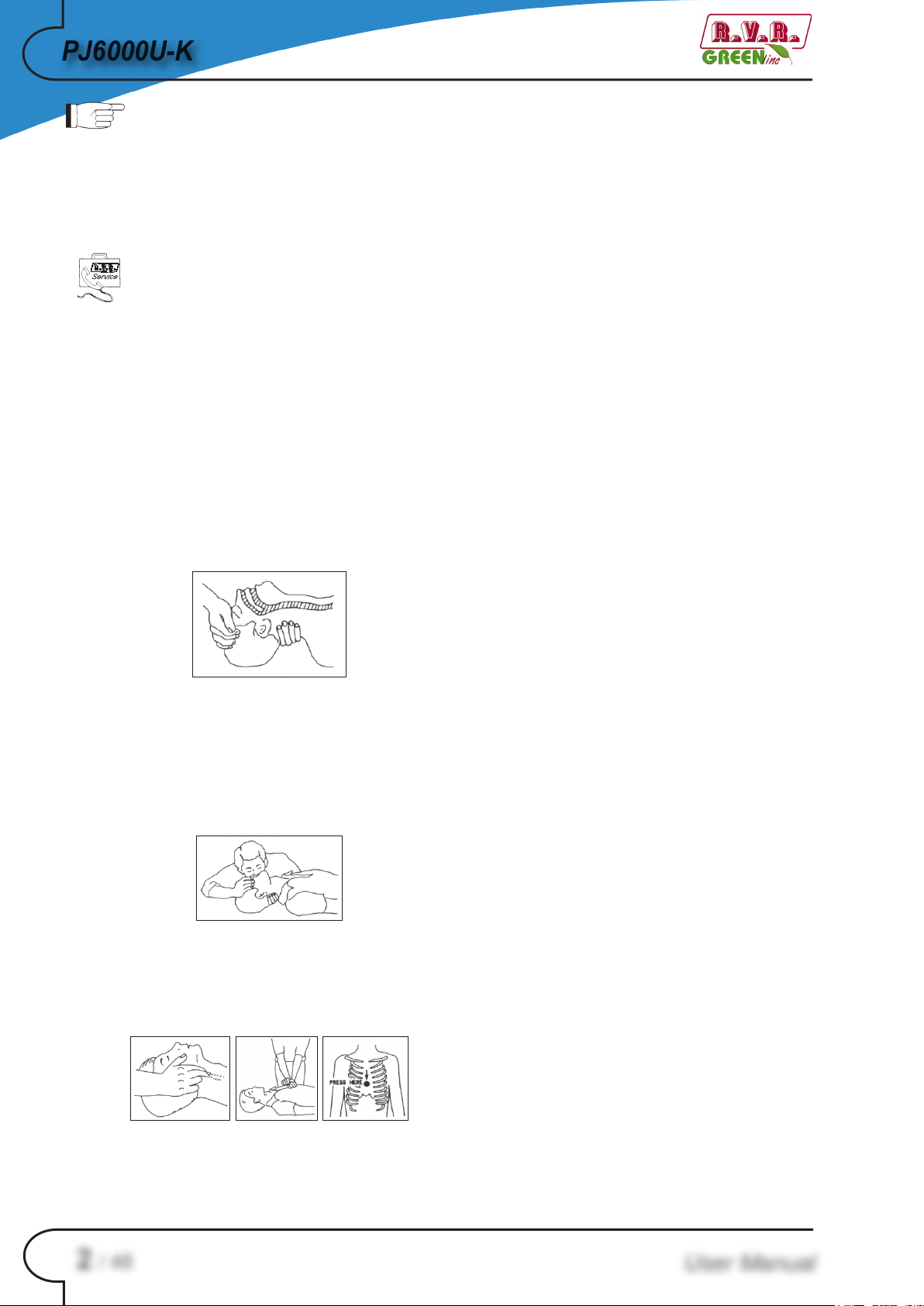
• the neck and tilt the head backwards to free
the airway system (Figure 1).
• Do not stop chest compressions while giving
artificial breathing.
• Call for medical help as soon as possible.
3.1.2 If the victim is conscious
• Cover victim with a blanket.
• Try to reassure the victim.
• Loosen the victim’s clothing and have him/her
lie down.
• Call for medical help as soon as possible.
3.2 Treatment of electric burns
3.2.1 Large burns and broken skin
• Cover affected area with a clean cloth or
linen.
• Do not break any blisters that have formed;
remove any clothing or fabric that is stuck to
the skin; apply adequate ointment.
• Administer adequate treatment for the type of
accident.
• Get the victim to a hospital as quickly as
possible.
• Elevate arms and legs if injured.
If medical help is not available within an hour, the victim is
conscious and is not retching, administer a solution of table
salt and baking soda (one teaspoon of table salt to half
teaspoon of baking soda every 250 ml of water).
Figure 1
• If needed, open the victim’s mouth and check
for breathing.
• If there is no breathing, start artificial respiration
without delay (Figure 2) as follows: tilt the head
backwards, pinch the nostrils, seal your mouth
around the victim’s mouth and give four fast
rescue breaths.
Figure 2
• Check for heartbeat (Figure 3); if there is
no heartbeat, begin chest compressions
immediately (Figure 4) placing your hands in
the centre of the victim’s chest (Figure 5).
Have the victim slowly drink half a glass of solution for four
times during a period of 15 minutes.
Stop at the first sign of retching.
Do not administer alcoholic beverages.
3.2.2 Minor burns
• Apply cold (not ice cold) strips of gauze or dress
wound with clean cloth.
• Do not break any blisters that have formed;
remove any clothing or fabric that is stuck to
the skin; apply adequate ointment.
• If needed, have the victim change into clean,
dry clothing.
• Administer adequate treatment for the type of
accident.
• Get the victim to a hospital as quickly as
possible.
• Elevate arms and legs if injured.
Figure 3 Figure 4 Figure 5
2 / 48
• One rescuer: give 2 quick rescue breaths after
each 15 compressions.
• Two rescuers: one rescue breath after each 5
compressions.
Rev. 1.0 - 21/03/18
User Manual

3 / 48
Rev. 1.0 - 21/03/18
4. General Description
The PJ6000U-K is an radio broadcasting amplifier manufactured by R.V.R.
Elettronica SpA featuring adjustable RF power output up to 6000 W under 50
Ohm standard load and less than 70 W drive power requirement..
The PJ6000U-K is designed to being contained into a 19” rack box of 4HE.
4.1 Unpacking
The package contains:
1 PJ6000U-K
1 User Manual
1 Mains power connector to be wired
The following accessories are also available from Your R.V.R. Dealer:
PJ6000U-K
• Options for the machine: /LD-PJ
• Spare Parts
• Cables
4.2 Features
The overall efficiency of PJ6000U-K is better than 70% across the bandwidth, for
this reason are part of RVR Green Line family.
This performance characteristic is guaranteed in a range between +0.25 dB and -3
dB (+5% and -50%) referred to the nominal power of the equipment: for example
from 3000W to 6300W in case of PJ6000U-K; outside these limits the equipment
is able to work properly but can not guarantee an efficiency of 70%.
The operating logic during the output power regulation, which is necessary in
order to not deteriorate the efficiency even of 5-6%, expects to set the pilot power
to the optimum power (dependent on the amplifier: for example the PJ6000U-K
requires 50 W) and then successively adjust the bar setting of power on amplifier
in order to obtain the desired output power.
User Manual
The amplifier incorporates a low-pass filter to keep harmonics below the limits
provided for by international standards (CCIR, FCC or ETSI).
Two major features of PJ6000U-K are compact design and user-friendliness.
Another key feature is its modular-concept design: the different functions are
performed by modules with most connections achieved through male and female
connectors or through flat cables terminated by connectors. This design facilitates
maintenance and module replacement.

PJ6000U-K
The RF power section of PJ6000U-K uses eight LD-MOSFET (MRFE6VP61K25H)
modules delivering up to 750W output power each.
An LCD on the front panel and a push-button panel provide for user interfacing with
the microprocessor control system, which implements the following features::
• Output power setup.
• Power output enable/disable.
• User-selectable threshold settings for output power alarm (Power GoodUser-selectable threshold settings for output power alarm (Power Good
feature)
• Measurement and display of amplifier operating parameters.
• Communication with external devices such as programming or telemetry
systems via RS232 serial interface or I2C.
Four LEDs on the front panel provide the following status indications: ON, LOCAL,
FOLDBACK and RF MUTE. On left side, four LEDs provide indications relatively
the status of RF signal amplified: FAULT, FUSE BLOWN, FOLDBACK and ON.
At last, on right side, four LEDs provide indications relatively the fault status of
power supplies: PS1, PS2, PS3 and PS SERVICE.
The amplifier management firmware is based on a menu system. User has four
navigation buttons available to browse submenus: ESC , , , ed ENTER.
The rear panel features the mains input connectors, RF power input connectors
that allows its use with common mains voltages, telemetry connector, protection
fuses, interlock input and interlock output connectors, I2C connector, SERVICE
connector for programming and common bus connector for interfacing with other
PJ6000U-K in cascade.
IMPORTANT: The equipment works in three-phase, with a star center connection,
and can also be used in single-phase.
4 / 48
Rev. 1.0 - 21/03/18
User Manual
5 / 48
Rev. 1.0 - 21/03/18
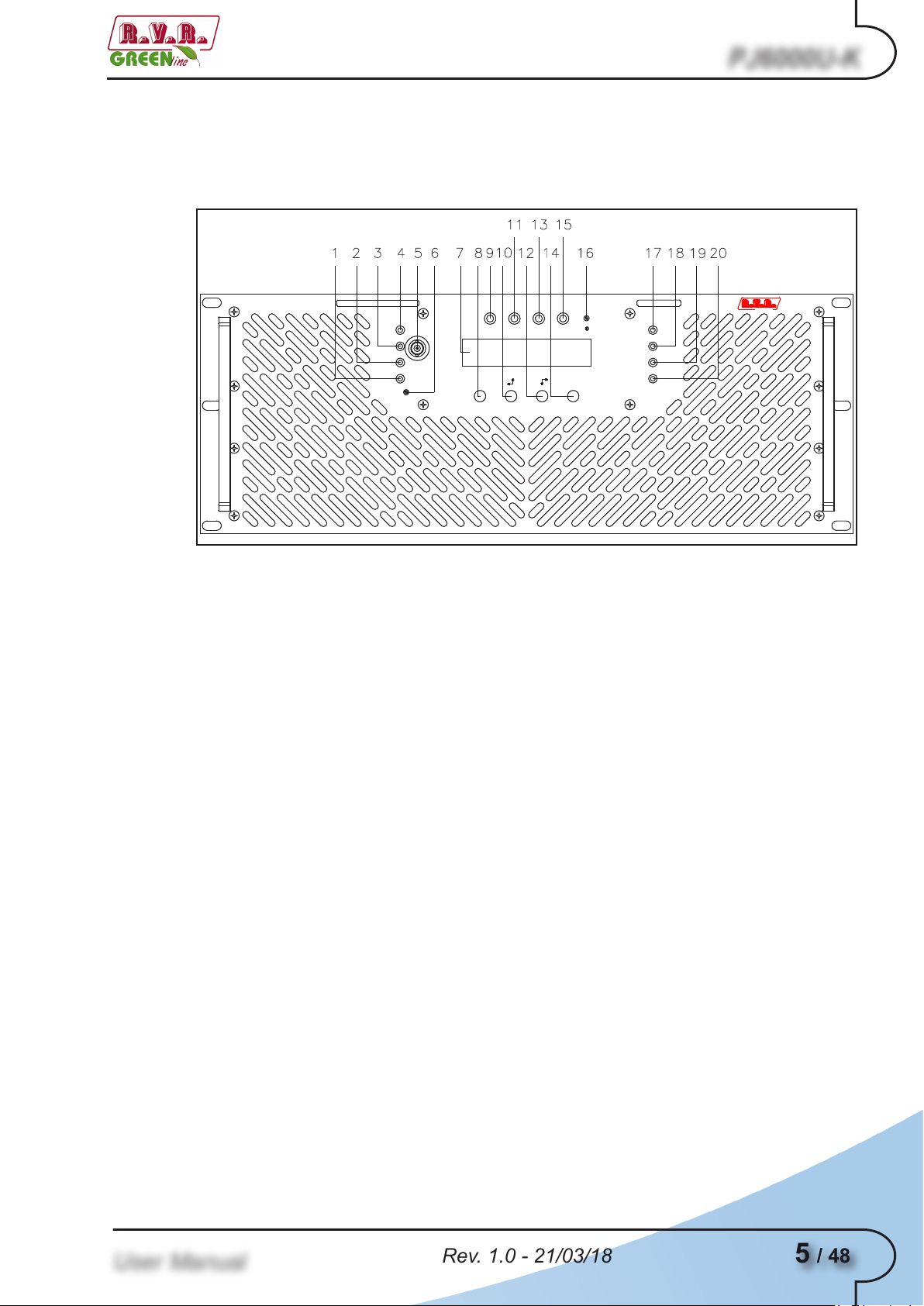
4.3 Frontal Panel Description
ELETTRONICA
F.M. AMPLIFIER
PJ6000U-K
FAULT
ON
FUSE
BLOWN
FOLD
BACK
RF POWER
ADJUST
ON LOCAL FOLDBACK RF MUTE
ENTER
ESC
PS1
PS2
PS3
PS
SERVICE
RF
TEST
MADE IN ITALY
BOLOGNA
ELETTRONICA
4.3.1 Frontal Panel Description of PJ6000U-K
PJ6000U-K
[1] ON Green LED, turns on when amplifier is switched on
[2] FOLDBACK Yellow LED, indicating that the foldback function is active
(automatic reduction of the distributed power)
[3] FUSE BLOWN Yellow LED, that indicates the presence of one or more
broken fuses
[4] FAULT Red LED, lit on in presence of a fault that can not be resolved
automatically
[5] RF TEST BNC connector for RF monitor output. The output level is
-60dB referred to the power output in 87.5 - 108 MHz range
[6] RF PWR ADJ Power regulation trimmer
[7] DISPLAY Liquid Crystal Display
[8] ESC Press this button to exit a menu
[9] ON Green LED, turns on when amplifier is powered on
[10] LEFT/UP Navigation button used to browse menu system and edit
parameters
[11] LOCAL Yellow LED, indicating that the amplifier is in local control
mode
[12] RIGHT/DOWN Navigation button used to browse menu system and edit
parameters
[13] FOLDBACK Yellow LED, indicating that the foldback function is active
(automatic reduction of the distributed power)
[14] ENTER Press this button to confirm a modified parameter and open a
menu
[15] RF MUTE Yellow LED, lit on when the amplifier’s power output is
inhibited by an external interlock command
[16] CONTRAST Trimmer to regulate the contrast of the LCD display
[17] PS1 Red LED, lit on when the power supply does not supply due
[18] PS2 Red LED, see point [17]
[19] PS3 Red LED, see point [17]
[20] PS SERVICE Red LED, lit on when one or more services power supplies
to a malfunctioning
does not supply due to a malfunctioning
User Manual

PJ6000U-K
4.4 Rear Panel Description
F3
F2F1
RF OUT
50 Ohm
MAINS
COMMON BUS
INTERLOCK
IN
TELEMETRY
SERVICEI²C BUS
RF IN
INTERLOCK
OUT
4.4.1 Rear Panel Description of PJ6000U-K
[1] TELEMETRY DB25 connector for telemetry
[2] INTERLOCK IN Interlock input BNC connector: to inhibit the amplifier from an
external device, like a dummy load
[3] RF IN RF input connector (“N” type)
[4] SERVICE DB9 connector for factory parameters programming (only for
factory programming)
[5] MAINS Plug for mains power supply
[6] PS1 Protection fuse of the power line 1
[7] PS2 Protection fuse of the power line 2
[8] PS3 Protection fuse of the power line 3
[9] COMMON BUS DB15 connector for interfacing with other devices
[10] INTERLOCK OUT Interlock output BNC connector: to inhibit an external device,
as an exciter. In case of fault, the inner connector is shorted
to ground
[11] I2C BUS DB9 connector for I2C bus networking
[12] RF OUT RF output connector (7/8” EIA flange)
6 / 48
Rev. 1.0 - 21/03/18
User Manual
7 / 48
Rev. 1.0 - 21/03/18
4.5 Connector Description
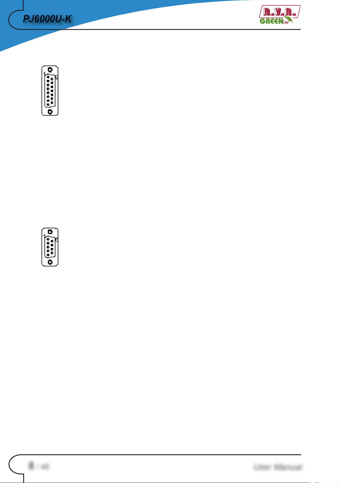
4.5.1 Telemetry
Type: Female DB25
1 Internal SWR 4,3V x F.S.
2 RF power amplifier voltage 3.9V x 50V
3 GND
4 Reflected Power 4.3V x F.S.
5 Interlock
6 Set 4
7 GND
8 “On” Command
9 Set 1
10 WAIT
11 Alarm Reset
12 OFF
13 Interlock
14 Temperature 3.9V x 100°
15 RF power amplifier voltage Current 4.3V x F.S.
16 Forward Power 4.3V x F.S.
17 FAULT
18 Set 3
19 Potenza in ingresso 4.3V x F.S.
20 “OFF” Command
21 GND
22 Set 2
23 LOC
24 +Vcc
25 ON
PJ6000U-K
4.5.2 I2C Connector
User Manual
Type: Female DB9
1 NC
2 SDA Serial Data
3 SCL Serial Clock
4 NC
5 GND
6 NC
7 NC
8 NC
9 NC
PJ6000U-K
4.5.3 Common Bus
Type: Male DB15
1 GND
2 RS 4853 ON-OFF C
4 IRQ C
5 PWR REG
6 NC
7 NC
8 NC
9 RS 485+
10 GND
11 ST-BY C
12 GND
13 GND
14 INHIBIT PJ-C
15 RESET PJ-C
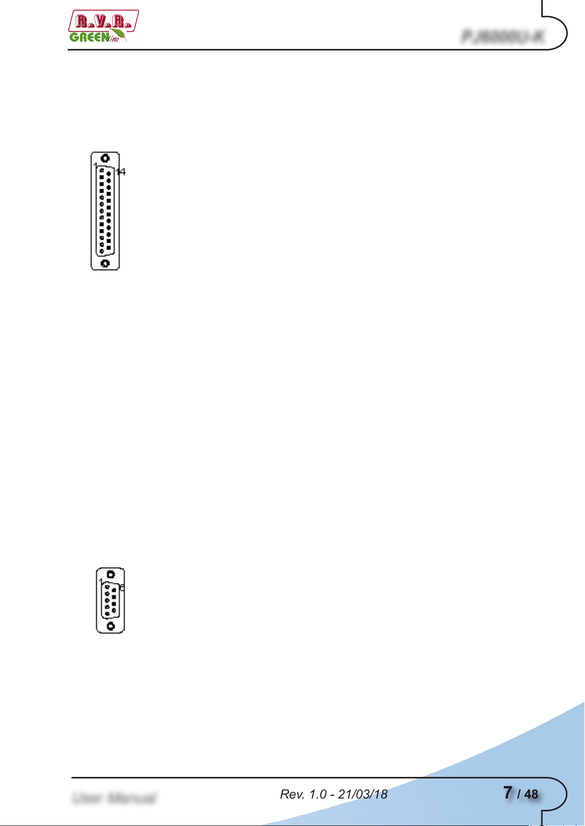
4.5.4 Service (for programming of factory parameters)
Type: Female DB9
1 NC
2 TX_D
3 RX_D
4 NC
5 GND
6 NC
7 Internally connected with 8
8 Internally connected with 7
9 NC
8 / 48
Rev. 1.0 - 21/03/18
User Manual
9 / 48
Rev. 1.0 - 21/03/18
5. Installation and use
This section provides a step-by-step description of equipment installation and
configuration procedure. Follow these procedures closely upon first power-on
and each time any change is made to general configuration, such as when a new
transmission station is added or the equipment is replaced.
IMPORTANT: always remove the mains voltage before carrying out any type of
installation and/or maintenance. It is essential to interrupt the power supply to
avoid the risk of electric shock which could cause material damage to people or
property, serious injuries and even death.
The equipment must only be installed by qualified personnel.
With qualified personnel, it identifies personnel who respond to all directives, laws
and regulations concerning safety, applicable to installation and operation of this
device.
The choice of qualified, and appropriately trained, personnel is always under
responsibility of the company in which this personnel is a part, because is the
company in question that determines whether a worker is suitable for a particular
job, in order to protect its safety by respecting the applicable law on workplace
safety matter.
PJ6000U-K
These companies must provide appropriate training to their staff on electrical
devices, and make sure that they familiarize themselves with the contents of this
manual.
The respect of the safety instructions set, forth in this manual or in the specified
legislation, does not exempt you from compliance with other specific regulations
regarding installation, place, Country or other circumstances affecting the
equipment.
IMPORTANT: there is a possible danger due electric shock, therefore it is mandatory
to comply with the applicable law on safety with regard to electrical aspects.
Once the desired configuration has been set up, no more settings are required
for normal operation; at each power-up (even after an accidental shutdown),
the equipment defaults to the parameters set during the initial configuration
procedure.
The topics covered in this section are discussed at greater length in the next
sections, with detailed descriptions of all hardware and firmware features and
capabilities. Please see the relevant sections for additional detail.
IMPORTANT: When configuring and testing the transmitter in which the equipment
User Manual
is integrated, be sure to have the Final Test Table supplied with the equipment ready
at hand throughout the whole procedure; the Final Test Table lists all operating
parameters as set and tested at the factory.

PJ6000U-K
5.1 Installation
5.1.1 Preliminary Requirements
The equiment ventilation and the work space must be suitable for maintenance
operations according to the directive in force in the country in which this device
is installed.
It is necessary to leave a minimum distance of 50 cm on the front and back sides
of the device to have a proper functioning and to facilitate air circulation through
the ventilation grids.
In any case, the device must respect the distance established by the safety directive
in force in the country where this equipment is installed.
This device is designed to operate at -10 °C to 45 °C without loss of performance.
The ambient air must be clean of dust and not condensed; the maximum humidity
must never exceed 95%.
It is important to remember that strong changes in temperature can lead to
generation of condensation, in particular environmental conditions. In case of the
station where this device is located should be subjected to these physical events,
it is good to monitor these devices, once you put it into service, in addition to trying
to protect the device itself as much as possible.
IMPORTANT: never supply voltage to the equipment in presence of condensation.
This problem can occur more frequently in devices warehoused for a long time or
in those used as an active reserve.
The antenna RF, power supply and connection cables must have the section
suitable for the maximum current intensity.
5.1.2 Preliminary checks
Unpack the transmitter and immediately inspect it for transport damage. Check
carefully that all the connectors are in perfect condition and check for the absence
of humidithy. Otherwise, wait until it is completely dry.
In case of problems in this step, immediately contact after-sales assistance.
10 / 48
Rev. 1.0 - 21/03/18
User Manual
11 / 48
Rev. 1.0 - 21/03/18
The mains power supply protection fuses are conveniently located externally on
rear panel. Remove the fuse holder with a screwdriver to check its integrity or to
replace it if necessary. The following fuse are used:
Mains fuses 1-2-3 (3x) 25A-T type 10x38
5.1.2 Placement of equipment
Useful tips for a correct installation:
• Do not use in presence of external elements near inlets and outlets ventilation
systems, as they could prevent a proper ventilation of the device.
• Do not place near any source of heat or flammable gas.
• Avoid places subject to accumulation of humidity, dust, sand, salt or environments
that could compromise the correct operation of the equipment.
PJ6000U-K
PJ6000U-K
Table 5.1: Fuses
• Avoid installing the equipment into inhabited places due to possible noise
pollution or on fragile supports. The operation of the equipment can cause a
noise due to forced ventilation. The mounting surface must be able to withstand
the weight of the device and must be sturdy.
Note: below we will refer to a complete station, where the device can be a part of
it. The same procedures also apply in case of the device is used individually.
The device is usually connected inside a 19 “rack and fixed with M5 screws in the
appropriate holes.
The equipment must be installed at least 1 mt from the ground.
Install the rack in the point in which the transmitter will be put in operation. The
rack is mounted on wheels for easy movement so that, once placed in the desired
location, it is advisable to use the four screws located at the base of the rack to
stabilize it perpendicularly to ground.
The environment, where you have decided to install the rack, should be set up
for about 25°C of air conditioning and equipped with a filter to remove dust and
salt air.
User Manual

PJ6000U-K
The transmitter normally have the outlet air in the back of machine.
COLD
HOT
50cm
COLD
HOT
50cm
In this case, provide adequate ventilation of the room.
In alternative is cooled by forced ventilation and the air outlet is located on the roof
of machine. Is recommended a length of tube approximetively of 1,5 meter.
12 / 48
Is highly recommended to install the rack at least 50 cm from the rear and side
wall so as to allow an optimum air flow and to facilitate workers.
Rev. 1.0 - 21/03/18
User Manual

13 / 48
Rev. 1.0 - 21/03/18
50cm
50cm
COLD
HOT
5.1.2.1 Rack power supply connections
PJ6000U-K
Provide for the following (applicable to operating tests and putting into service):
√ Mains power supply 230 VAC or 400 VAC for PJ6000U-K, both with adequate
earth connection.
√ For operating tests only: dummy load with 50 Ohm impedance and adequate
capacity (6000W as a minimum for PJ6000U-K).
Connect the overall power cord of machine. The cable can be slid through the
cable gland located on the back, or on the roof, of the machine and conductors
must be attached to the general disconnecting switch terminals.
Note: The connection of machine to power supply is done by fixing a multi-pole
cable with exposed terminals to a terminal board. Make sure, with no possibility
of error, that the cable is not under tension when you connect it to the machine.
WARNING: Is highly recommended to don’t turn on the machine without first
having connected the RF output to antenna or dummy load!
If you have a dummy load capable to dissipate the RF power generated by the
transmitter, it is advisable to carry out first tests by linking to it rather than to the
transmission antenna.
User Manual
If transmitter require a single-phase power with F (black or brown or grey) + NF (black or brown or grey) + N
(blue) + GND (green yellow), keep in mind this requirement to connect to your, keep in mind this requirement to connect to your
distribution board.

PJ6000U-K
L N PE
If transmitter require three-phase power with 3F (black, brown and grey) + N3F (black, brown and grey) + N
R S T N PE
CONNECTOR
THREE-PHASE
CABLE SECTION
SINGLE-PHASE
CABLE SECTION
L
/ Ø 6mm
R
Ø 4mm /
S
Ø 4mm /
T
Ø 4mm /
N
Ø 4mm Ø 6mm
PE
Ø 4mm Ø 6mm
(blue) + GND (green yellow), keep in mind this requirement to connect to your, keep in mind this requirement to connect to your
distribution board.
Note: the mains must be equipped with adequate earth connection properly
connected to the equipment. This is a pre-requisite for ensuring operator safety
and correct operation.
The following table shows the recommended cable cross-sections:
14 / 48
Tipically the distribution board contains the thermal-magnetic circuit breakers for
each amplifier included in the system and one for service.
Rev. 1.0 - 21/03/18
User Manual

15 / 48
Rev. 1.0 - 21/03/18
WARNING: Electric shock hazard! Never handle the RF output connector
when the equipment is powered on and no load is connected. Injury or death
may result.
Ensure that the distribution board of the transmitter is set to “OFF”.
5.1.3 Device power supply connections
PJ6000U-K
Provide for the following (applicable to operating tests and putting into service):
√ Single phase mains power supply (P+N) 230 VAC (-15% / +10%) or three phase
mains power supply (3P+N) 400 VAC (-15% / +10%) , both with adequate earth
connection.
√ FM exciter with adjustable output power up to 50W (minimum), as the RVR
Elettronica PTX60LCD/S.
√ For operating tests only: dummy load with 50 Ohm impedance and adequate
capacity (6000W as a minimum).
Nota: to ensure the safety of the operators, carry out the wiring according to the
laws and regulations in force in the country where this equipment is installed.
Check that the POWER switch on the front of PJ6000U-K is in the “OFF”
position..
An ILME model KKCNTCQF04/2 (CQF04/2) multipole socket is supplied with the
amplifier to power the machine. The socket must be connected to the multipole
cable that will be wired to the mains switchboard.
WARNING: to avoid any risk of shock make absolutely sure that the power
supply cable is NOT powered when the multipole socket is connected to the
cable itself..
User Manual
Connect the multipole socket to the power supply cable as described below and
refer to figure 5.1:

PJ6000U-K
Three-phase power supply:
3
2
12 4
11G1
• G Ground
• 1 R Phase
• 2 S Phase
• 3 T Phase
• 4 Neutral
• 11,12 Not connected
Figure 5.1: View of the mains multipole socket - terminals side (internal)
Connect the mains cable to the appropriate MAINS VOLTAGE terminal block on
the rear panel..
Warning: Be sure to connect the equipment correctly, to avoid the risk of
damaging. It is necessary connect the ground conductor of the power supply
cable to the specific terminal in the multipole socket and check the efficiency of
your own grounding system.
The control and RF connection diagram, between the amplifier and its exciter,
and the connection with the load are represented in figure 5.2.
Note: to ensure both the safety of the operators and the correct functioning of
the apparatus, it is essential that the network system is grounded, and that it is
properly connected to the equipment.
Useful tips for a correct connection:
• Provide an adequate grounding of the electrical system. This has both a direct
protection function, as it prevents receiving shocks by touching directly the
metallic enclosures of the equipments, as well as an indirect protection function,
as it interrupts the energy supply when a leak occurs due to poor insulation.This
is possible on its own even through discharge devices, like the installation of
a picket and an inspectable cockpit, through specific companies with qualified
personnel to carry out the work.
16 / 48
Rev. 1.0 - 21/03/18
User Manual

17 / 48
Rev. 1.0 - 21/03/18
• Provide an internal lightning protection such as a surge arrester (internal SPD)
or a thermal-magnetic circuit breaker, requiring the installation in the distribution
panel through qualified personnel. This solution allows you to protect from
violent atmospheric electric shocks that strike the surrounding ground up to
several kilometers.
• Provide an internal protection against interference on the distribution line
such as EMI filters or stabilizers on line voltages, rrequiring the installation
in the distribution panel through qualified personnel, which allow to filter the
interferences caused by electrical equipment and sudden surges of the line,
in addition to providing a voltage regulation.
5.1.4 RF Connections
Provide for the following setup (applicable to operating tests and putting into
service):
√ Connection cable kit including:
PJ6000U-K
• Mains power cable.
• Coaxial cable with BNC connectors for interlock signal connection between
exciter and amplifier.
• RF cable for output to load / antenna (50 Ohm coaxial cable with standard N
connector).
• Audio cables between transmitter and audio signals sources.
WARNING: risk of burns due to RF. Make sure that the device can not emit
RF at the output, before connecting the antenna cable.
WARNING: For electromagnetic compatibility reasons, only double shielded
cables must be used on the RF output.
Don’t forget to equip yourself with a 7/8“ 50 Ohm RF cable for the connection
between the Antenna and the device; the part that goes towards the device must
be equipped with a 7/8“ type connector.
Connect the RF output of the transmitter to an antenna cable or to a dummy load
capable of dissipating the power generated by the amplifier. To begin with, set
exciter to minimum output power and switch if off.
User Manual
Connect the amplifier INTERLOCK OUT output to the matching INTERLOCK IN
input fitted on all R.V.R. Elettronica exciters as standard; if your exciter is a different
brand, identify an equivalent input.
Connect the RF output to an adequately rated dummy load or to the antenna.

PJ6000U-K
F3
F2F1
RF OUT
50 Ohm
MAINS
COMMON BUS
INTERLOCK
IN
TELEMETRY
SERVICEI²C BUS
RF IN
INTERLOCK
OUT
WARNING: To avoid electrical shock and electrocution, never touch the RF
output connector when the equipment is switched on and no dummy load
is connected.
Connect the audio and RDS/SCA cables of own sources to the input
connectors.
5.2 Operation
1) After having plugged in the power supply socket at the back of the machine, After having plugged in the power supply socket at the back of the machine,After having plugged in the power supply socket at the back of the machine,
power on the amplifier via the switchboard. The ON LEDs will turn on and the
forced cooling blowers will start running. The LCD shows the first introductory
screenful and then switches to a screenful that indicates the forward and
reflected power values..
Figure 5.2: Connections with exciter
18 / 48
Menu 1
2) Rotate trimmerRotate trimmer RF PWR ADJ completely counterclockwise to set the power to
0.
3) Adjust the exciter output, to which this amplifier is connected, to have 50W at
amplifier input.
Rev. 1.0 - 21/03/18
User Manual

PJ6000U-K
19 / 48
Rev. 1.0 - 21/03/18
4) Adjust output power using RF PWR ADJ trimmer.
5) At this point, the amplifier is adjusted to its nominal power.
Note: After ten minutes, readjust the output power of the amplifier(s), it will be
lowered due to heating. Repeat the procedure if the carrier frequency is
changed.
Note: the amplifier does not have AGC function, but only have security
features.
WARNING: Machine is capable of delivering more than rated output powerWARNING: Machine is capable of delivering more than rated output power
(6000 W); however, never exceed the specified power rating.
NNOTE: Exciter drive power setting should never exceed 50W, or it will trigger
an Overdrive Alarm.
Next, you can review all operating parameters of the machine through the
management firmware.
Normally, the machine can run unattended. Any alarm condition is handled
automatically by the safety system or is signalled by the LED indicators on the
panel or by display messages.
NOTE: Standard factory settings are: output power set to upper limit (unless
otherwise specified by customer) and OFF.
5.3 Management Firmware
The machine features an LCD with two lines by 16 characters that displays a set
of menus. Figure 5.2 below provides an overview of machine menus.
The symbols listed below appear in the left portion of the display as appropriate:
(Cursor) - Highlights selected (i.e. accessible) menu.
(Filled arrow) - Editable parameter marker. This symbol appears in menus that
take up more than two lines to aid browsing.
(Three empty arrows) - Parameter is being edited.
(Empty arrow) - Current line marker; the parameter in this line cannot be
edited. This symbol appears in menus that take up more than two lines to aid
browsing.
User Manual

PJ6000U-K
Menu 1
Operation Menu
Power Menu
P.A. Menu
Alarm Menu
Version Menu
Miscellaneous menu
Menu 3
Menu 4
Menu 5
Menu 6
Menu 7
Menu 8
Menu 9
Selection Screen
Default Menu
Figure 5.2
When the display is off, touching any key will turn on backlighting.
When the display is on, pressing the ESC button from the default menu (menu 1)
calls up the selection screen (menu 3), which gives access to all other menus:
Menu 3
5.3.1 Operation Menu (Fnc)5.3.1 Operation Menu (Fnc)
20 / 48
To gain access to a submenu, select menu name (name is highlighted by cursor)
using button or and press the ENTER button.
Press ESC again to return to the default menu (menu 1).
In this menu, you can set power output On/Off, toggle between “Local” or “Remote”
control mode and set the Forward Power Good (PgD) threshold rate.
Rev. 1.0 - 21/03/18
User Manual

PJ6000U-K
21 / 48
Rev. 1.0 - 21/03/18
To edit an item, highlight the appropriate line using the UP and DOWN buttons and
then press and hold the ENTER button until the command is accepted. This way,
Pwr setting is toggled between On and Off and Mod setting is toggled between
“x1” and “x10”. To edit the Power Good rate, simply select item “PgD” and edit its
value using buttons and ; finally, press ENTER to confirm.
Menu 4
Pwr Enables (ON) or disables (OFF) amplifier power output.
Loc Modifies machine operation. In the LOCAL mode, the machine can read
and modify its operating parameters through the navigation keys and the
management firmware, whereas all other sources are locked out. In the
REMOTE mode, the machine can only read its operating parameters;
parameters are modified based on the commands received from other
connected telemetry systems.
Pg1 Modifies Power Good (forward power) threshold. The Power Good rate
is a percent of machine rated power (6000W for PJ6000U-K), not of
forward output power. This means that this threshold set at 50% will
give 3000 W regardless of set power level. The Power Good feature
enables output power control and reporting. When output power drops
below set Power Good threshold, the equipment changes the state of
pin [9] of the DB25 “Remote” connector located on the rear panel..
Pg2 Like Pg1, modifies a second Power Good threshold for forward
power. When output power drops below set Power Good threshold,
the equipment changes the state of pin [22] of the DB25 “Remote”
connector located on the rear panel..
Pg3 Like Pg1, modifies Power Good threshold for reflected power. When
output power drops below set Power Good threshold, the equipment
changes the state of pin [18] of the DB25 “Remote” connector located
on the rear panel..
User Manual
Pg4 Like Pg1, modifies a second Power Good threshold for reflected
power..

PJ6000U-K
5.3.2 Power Menu (Pwr)
This screen holds all readings related to machine output power:
Note that these are readings, rather than settings, and cannot be edited (note
the empty arrow). To change power setting, go to the default menu (menu 1) as
outlined earlier.
Fwd Forward power reading.
R Reflected power reading.
Inp Input power reading.
Menu 5
5.3.3 Menù Power Amplifier (P.A)
This screen is made up of four lines that can be scrolled using the buttons and
, shows the readings relating to final power stage:
Note that these are readings, rather than settings, and cannot be edited (note the
empty arrow).
VPA Voltage supplied to amplifier module.
IPA Current absorbed to amplifier module.
Menu 6
22 / 48
Eff Efficiency based on ratio of forward power to amplifier module power
in percent ( FWD PWR/(Vpa x Ipa) % ).
Tmp Machine internal temperature.
Rev. 1.0 - 21/03/18
User Manual

23 / 48
Rev. 1.0 - 21/03/18
5.3.4 Alarm Menu (Alm)
This menu shows any alarm conditions occurring during machine operation. Alarm
thresholds are preset at the factory.
FWD Counter of alarm conditions triggered by forward power.
RFL Counter of alarm conditions triggered by reflected power.
INP Counter of alarm conditions triggered by input power.
PJ6000U-K
Menu 7
Reset Alm Alarm counter reset.
Alarm conditions are numbered from 1 to 10 and reflect the following situations:
forward output power too high, reflected output power too high and input power
too high.
Alarm monitoring cycle is as follows: when an alarm condition is detected, alarm
counter increases by 1 unit, machine goes into lock-out state and the display
shows the cause for the stop. After 15 seconds, the machine attempts to re-start;
if a new alarm condition is detected, cycle is repeated over and over again up to
10 times maximum.
If machine re-starts successfully, all alarm counters are reset after 30 minutes’
regular operation. After 10 alarm conditions triggered by the same cause, the
machine goes into fault lock-out mode, a lock-out mode warning appears on the
display and the “FAULT/LOCK” LED turns on.
After the alarm condition has been rectified, the counter can be reset by highlighting
“Reset Alm” and holding down the ENTER key for some time.
5.3.4.1 Alarms and Faults
User Manual
There are three types of alarms that can cause a machine lock-out and trigger
a “FAULT/LOCK” indication. When any one of the three alarm thresholds is
exceeded, the system will automatically switch to the warning screen (even
though the user is browsing system menus) and the following messages
are displayed:

PJ6000U-K
1. Over Forward Power
Forward power threshold exceeded.
2. Over Reflected Power
Reflected power threshold exceeded.
3. Over Input Power
Alarm 1
Alarm 2
Input power threshold exceeded.
Alarm 3
Monitoring cycle is as follows:
• An alarm condition occurs;
• Alarm is displayed and device is locked out for 15 sec.;
• Operating conditions are restored;
• Verification.
Upon reaching the 10 cycle limit, a “FAULT/LOCK” indication is triggered and the
device goes into lock-out mode; the appropriate LED turns on (figure 6.1) and this
screen is displayed:
I. Over Forward Power
24 / 48
Forward power alarm display.
Rev. 1.0 - 21/03/18
Stop 1
User Manual

25 / 48
Rev. 1.0 - 21/03/18
II. Over Reflected Power
Reflected power alarm display.
III. Over Input Power
Input power alarm display.
PJ6000U-K
Stop 2
Stop 3
Once the machine goes into “FAULT” mode, it will no longer attempt to re-start;
choose the appropriate reset procedure according to current machine setting:
• Machine set to LOCAL control mode - press “Reset Alm” in the alarm menu
(menu 7) or power off and back on again using the POWER switch.
• Machine set to REMOTE control mode - power off and back on again sending
the appropriate command via the DB25 connector (pin [8] and [20]).
There is a fourth alarm that does not trigger a “FAULT” condition, but allows some
time until correct operating conditions are restored. When the temperature alarm
threshold is exceed (about 85°C), the following screen appears:
4. Over Temperature
Temperature power threshold exceeded.
Alarm 4
5.3.5 Miscellaneous Menu (Mix)
User Manual
This screen holds machine version/release information:
Menu 8

PJ6000U-K
IIC I
2
C address setting. The I2C network address becomes significant when
the exciter is connected in an RVR transmission system that uses this
protocol. Do not change it unless strictly required.
5.3.6 Version Menu (Vrs)
This screen holds machine version/release information:
Note that these are readings, rather than settings, and cannot be edited (note the
empty arrow).
Rel Firmware release information.
Menu 9
Dat Release date.
Tab Shows table loaded in the memory.
5.4 Protection SystemProtection System
The protection system implemented inside the amplifier is based on two types of
intervention.
The first reaction is called “Foldback” and consists in decreasing the voltage in
the power amplifier when the forward or reflected power exceeds the proportional
limit voltage value. As such, the amplifier’s gain is reduced and the overall result is
an action that opposes the increase of the forward or reflected power. The yellow
LED on the front panel indicates the tripping of the foldback circuit..
The second type of reaction consists in turning OFF the equipment’s amplifying
section when a specific variable exceeds a set value..
Depending on the type of event that has occurred, after that the amplifier has
been turned off, it will be reactivated after a fixed time interval or only after that
the sharing which caused the block has been removed..
26 / 48
When the protection system trips due to a “cyclic” type parameter, a counter
begins counting up (the X value in the alarm menu). If the counter reaches the max
admissible cycle value (Y), the amplifier turns OFF definitely and the red “FAULT”
LED lights up on the front panel..
Rev. 1.0 - 21/03/18
User Manual

27 / 48
Rev. 1.0 - 21/03/18
The user may press the ALARMS RESET key, in alarms menu, to interact with
the protection system. ..
If the system is transmitting but alarms were triggered earlier causing certain
counters not to be at “0”, will have no effect unless it is pressed while inside the
alarm menu. As such, the system will be sure that the user takes note of the alarms
that were triggered before resetting them..
The system resets the alarm counters automatically after thirty minutes of operation,
i.e. the user need not do anything, if the amplifier does not trigger any alarms or
after the machine the machine has been turned OFF and then back ON..
5.4.1 Auxiliary Protection
The amplifier contains a second microcontroller that manages local measurements
and carries out auxiliary protection functions of the machine together with the main
protection system. This microcontroller card indicates its interventions via LEDsii
interventi tramite i LED.
PJ6000U-K
A delivered power automatic back-off mechanism is envisaged for excess
temperature, SWR or current absorbed by a MOSFET module. The yellow
FOLDBACK LED indicates this case..
A FAULT signal is triggered (red LED) when a fault occurs that stops the power
amplifier. This situation is signaled to the machine’s main microcontroller as well
and triggers a lock situation (FAULT)..
The LED FUSE BLOWN indicates that one of the fuses that protects the power
supply of the MOSFET modules has blown. In this case the machine keeps running
as usual (obviously without the contribution of the module) even if it is advisable
to single out and clear the cause for the malfunction and replace the fuse as soon
as possible to fully restore the machine’s working efficiency..
5.4.2 Power Supply UnitsPower Supply Units
Three power supply units, which work in parallel mode, power the machine. Should
one of the power supply units malfunction, the machine automatically compensates
the delivered power down to a value compatible with the current deliverable from
the surviving power supply. This situation is indicated by the “PS” LEDs on the
front panel..
User Manual

PJ6000U-K
6. Identification and Access to the Modules
The PJ6000U-K is made up of various modules linked to each other through
connectors so as to make maintenance and any required module replacement
easier.
6.1 Upper view
The figure below shows the upper view of the machine with the various components
pointed out.
[1] Telemetry
[2] PFC
[3] Services Power Supplies
[4] Blower Control Board
[5] Power Supplies
[6] PWR Input Measure Card
[7] Bias e Measure Card
[8] CPU Card
[9] Signal Interface Card
[10] Status Led Card
[11] Panel Card
[12] PS Fault LED Card
figure 6.1
28 / 48
Rev. 1.0 - 21/03/18
User Manual

29 / 48
Rev. 1.0 - 21/03/18
6.2 Lower view
The figure below shows the lower view of the machine with the various components
pointed out.
PJ6000U-K
[1] Low Pass Filter and Combiner
[2] Amplifier Modules
[3] Bias Distributor and Splitter Card
[4] Pass-through Filter Card
figure 6.2
User Manual

PJ6000U-K
7. Working Principles
BPF 3° H
Load
FWD
RFL
Output
LPF
FWD
Bias Board
Interface Card
Service PS
&
Blower
Panel Card
PFC
PSL
PFC
PSL
PFC
PSL
Service PS
Service PS
Service PS
PA
True RMS Detector
/LD-PJ
(Low Power Option)
Input
The figures below provide an overview of PJ6000U-K (figure 7.1) modules and
connections.
30 / 48
Rev. 1.0 - 21/03/18
figure 7.1
User Manual

31 / 48
Rev. 1.0 - 21/03/18
7.1 PS Section
PFC
PSL
PFC
PSL
PFC
PSL
Interface Card
+50V
Panel Card
Bias
Service PS
&
Blower
AUX PS
AUX PS
AUX PS
The figures below provide a schematic view of PS section of PJ6000U-K (figure
7.2) modules and connections.
PJ6000U-K
7.1.1 PFC Unit
7.1.2 Power Supplies
User Manual
figure 7.2
The three PFC units are rectifiers that modulates the absorbed current so that the
wave shape is the most possible sinusoidal, obtaining a power factor with a cos φ
of 0.998 and can work with input supply voltages from 186 to 250 V..
The PFC units are mounted on a plate fixed to the central heat sink, in order to
allow an easy replacement in case of failures.
The three power supplies are located in the high part of the amplifier connected
in series to PFC units and deliver at the output an adjustable voltage from 20-50
VDC connected in parallel by a bus sharing system.
The power supplies are mounted on a plate fixed to the central heat sink, in order
to allow an easy replacement in case of failures.

PJ6000U-K
7.1.3 Services Power Supplies
The services power supplies present on this amplifier, providing a DC voltage of
24 VDC and have a maximum power of 130 W each.
7.1.4 Services PS control and Blowers
This module parallelizes the DC voltage of 24 VDC coming from the services
power supplies, and has a control line which allows to reduce the necessary output
power in the event of a fault in one of services power supplies or in case of lack
of one of supply phases, furthermore, it measures the temperature through the
sensor mounted on the main heatsink; this allows the automatic adjustment of the
blowers present on the machine.
7.1.5 Interface card
This card principally performs the interface function, processing and distribution of
several control signals generated by the various cards present in the equipment.
32 / 48
Rev. 1.0 - 21/03/18
User Manual

33 / 48
Rev. 1.0 - 21/03/18
7.2 RF Section
LPF
FWD
Bias
VPA/IPA
FWD
RFL
Output
Bias Board
S
P
L
I
T
T
E
R
C
O
M
B
I
N
E
R
PA1
PA2
PA3
PA4
PA5
PA6
PA7
PA8
Load
Load
Load
Load
Load
Load
Load
Load
BPF 3° H
Load
Input
The figures below provide a schematic view of PS section of PJ6000U-K (figure
7.3) modules and connections..
PJ6000U-K
7.2.1 PWR Input Measure Card
7.2.2 RF Power Amplifier
User Manual
figure 7.3
This card measures the input power and send it subsequently to the bias card,
which provides to send to protection in the event of excess power.
The RF modules, the splitter and the combiner are housed inside the lower part
of the equipment.
The RF amplifier section consists of 8 power modules coupled by an isochronous
combiner realized with coaxial cables hat guarantees reliability and durability..

PJ6000U-K
The splitter is used to divide input power from PWR Input Measure card and to
supply a part of it to every RF module. The combiner is used to combine output
power from every RF module so as to have total power amplifier.
Splitter, amplifier and combiner are plans so that powers generated from the
amplifiers add its in phase, diminishing the loss of balance and therefore the
dissipation of useful power.
All RF section is placed on a fin that supplies to the cooling through forced
ventilation.
Every RF module supplies 850 watts and is supplied from own switching supply.
The active device used in the amplifier modules is a single LD Mosfet.
The task of the low-pass filter is to reduce the harmonic emissions of the amplifier
to below the levels allowed by standards.
7.2.3 Bias Board
The task of this card is to measure the current drawn by the RF modules, and the
several input and output power, providing for fault reporting and the management
of their guards.
This card also carries the signals to the DB15 connector, located on the rear panel
of the equipment, in RS485 standard for uses in multiple amplifiers systems
The card also manages the /LD-PJ option, if it were installed in the machine.
7.2.4 Directional Coupler
The task of this card is to take a part of RF signal and send it to the interface card,
where it will be straightened and measured.
The directional coupler is an integral part of output connector.
34 / 48
Rev. 1.0 - 21/03/18
User Manual

35 / 48
Rev. 1.0 - 21/03/18
7.3 Logic Section
Inerface Card
Panel Card
Bias
RF Fault Leds Card
PS Leds Status Card
The figures below provide a schematic view of Logic section of PJ6000U-K (figure
7.4) modules and connections.
PJ6000U-K
7.3.1 RF status LEDs Card
This card is fitted with four warning LEDs that indicate the machine’s general
operating status.
It also has a trimmer for adjusting power. Use a small screwdriver to change the
delivered power.
7.3.2 PS status LEDs Card
Three LEDs are present on this board for indicating the operating status of the
three power supply modules and a fourth LED indicating the status of the service
supplies.
The lighting up of a LED indicates a malfunction in the associated module.
7.3.3 Scheda Pannello
figure 7.4
User Manual
The panel board accommodates the microcontroller that runs the machine control
firmware and all user interface elements (display, LED’s, keys, …).
This board is interfaced with other machine modules via flat cables to facilitate the
replacement of module in case of failures.

PJ6000U-K
This card carries the signals to the DB25 telemetry connector that is on the
machine’s back panel. The connector is fitted with 7 analog outputs, 8 open
collector digital outputs and 4 digital inputs. It also manages the DB9 connector
for communications in I2Cstandard.
36 / 48
Rev. 1.0 - 21/03/18
User Manual

37 / 48
Rev. 1.0 - 21/03/18
8. “Low-Drive Power” Option (/LD)“Low-Drive Power” Option (/LD)
LPF
FWD
Bias
VPA/IPA
Driver
Input
FWD
RFL
Output
Bias Board
Driver
VPA/IPA
Driver
Bias
S
P
L
I
T
T
E
R
C
O
M
B
I
N
E
R
PA1
PA2
PA3
PA4
PA5
PA6
PA7
PA8
Load
Load
Load
Load
Load
Load
Load
Load
BPF 3° H
Load
The figures below provide a schematic view of RF section of PJ6000U-K (figure
8.1) modules and connections.
PJ6000U-K
8.1 “Low-Drive power” Board
User Manual
figura 8.1
The “Low-Drive power” board contains an RF amplifier with only one stage that,
with a power of about 1W, can supply an output power of approximately 50W
suitable to pilot the amplifier.
The active device utilized in the amplifier modules is a Mosfet and uses for the
feeding the same voltage of 50VDC used from the eight RF amplifiers modules.
On the output stage of this board is present a directional coupler that measure the
reflected and forward power; the latest comes acquired from the control software
that represents it legible like input power.
The board is mounted on the fin that supplies to its cooling through forced
ventilation..

PJ6000U-K
9. Maintenance and repair procedures
9.1 Introduction
This section provides general information about maintenance and electrical settings
for the PJ6000U-K amplifier.
The maintenance is separated into two sections depending on the complexity
of the procedure and the instrumentation required for the test to complete the
maintenance.
9.2 Security Considerations
Dangerous voltages and high currents are present inside the amplifier, when it is
working; strong power RF signals are present, also.
WARNING: Do not remove any covers without first turning the equipment off
and making sure that you have closed them all before restarting the equipment.
Be sure to disconnect the amplifier’s mains supply before proceeding to any
maintenance operation on the system.
9.3 Ordinary maintenance
The only regular maintenance required on the PJ6000U-K is the periodic blower
replacement and dust cleaning of the air filter and of any trace of it inside the
amplifier.
The frequency of these operations depends on the operating conditions of the
machine: like ambient temperature, dust level in the air, humidity, etc ...
It is advisable to make a preventive inspection every 6 months, and to replace the
blowers that has abnormal noises.
The blowers should be replaced, in case of problems, as soon as possible and in
any case not later than 24 months.
38 / 48
Rev. 1.0 - 21/03/18
User Manual

39 / 48
Rev. 1.0 - 21/03/18
9.3.1 How to replace a malfunctioning blower
A
C
B
• Unscrew all screws A on the front panel of PJ6000U-K.
• Disconnect the power fan connector B, unscrewing the two slotted screws
present.
PJ6000U-K
• Unscrew the four screws C and remove the malfunctioning blower.
• Insert the new blower (mod. 9GV0824P1G03 Sanyo-Denki) and retighten the
four fixing screws C.
• Reconnect the connector in the position B and secure it with two screws.
• Replace the front cover and screw all the screws into the position A.
9.4 Module substitutions
Only authorized and qualified technical personnel must be proceed with the
replacement of the component parts in the relevant device.
9.4.1 How to replace the RF module
• Open the bottom cover of PJ6000U-K by unscrewing all the screws.
• Identify the RF module to be replaced by a visual inspection, a check on the
voltage and/or the verification of a possible broken fuse.
User Manual

PJ6000U-K
m
o
d
u
l
e
1
m
o
d
u
l
e
2
m
o
d
u
l
e
3
m
o
d
u
l
e
4
m
o
d
u
l
e
5
m
o
d
u
l
e
6
m
o
d
u
l
e
7
m
o
d
u
l
e
8
• Disconnect connector A and unsolder points B.
B
A
C
• Unscrew all the Allen screws located in positions C.
40 / 48
• At this point, replace the module, placing on the back of the new RF module
some Compound paste with high thermal conductivity and without silicones.
We recommend the Compound paste of the HTC Electrolube, or equivalen.
Rev. 1.0 - 21/03/18
User Manual

PJ6000U-K
41 / 48
Rev. 1.0 - 21/03/18
D
E
• Replace the RF module in its housing and resolder the points B points.
• Place an amperometer in series to 50VDC (see points D). Verify, with the
equipment switched on but without power input, that there are 1A otherwise
intervene on the trimmer E until to the reading of the indicated value. However,
if the amperometer does not provide any indication, it is very probabely that
the fuse is broken.
Proceed with its replacement by following the next chapter.
9.4.2 How to replace the fuses
User Manual
• At this point, screw the screws into the position C.
• Reconnect the connector in its housing A.
• Put the cover back on and tighten all the screws necessary to close it.
• Unscrew all screws A on the front panel of PJ6000U-K.

PJ6000U-K
A
• Identify the broken fuse.
Fuse 1
Fuse 2
Fuse 3
Fuse 4
Fuse 5
Fuse 6
Fuse 7
Fuse 8
B
• Replace the broken fuse, with one of equal value, as in point B.
9.4.3 How to replace the power supply
42 / 48
• Redo all previously steps, performed in reverse, in order to reassemble
everything.
• Open the top cover of PJ6000U-K by unscrewing all the screws.
• Identify the power supply module to be replaced based on the signaling LED
on the front panel.
Rev. 1.0 - 21/03/18
User Manual

43 / 48
Rev. 1.0 - 21/03/18
Module 1
Module 2
Module 3
• Unscrew all the points A with the help of an Allen screwdriver.
A
PJ6000U-K
• Remove the two plates near points A.
• Disconnect all the connectors at positions B and unscrew all the points C with
the help of an Allen screwdriver.
User Manual

PJ6000U-K
B
C
• Remove the power supply module and replace it with a new spare part.
• Redo all previously steps, performed in reverse, in order to reassemble and fix
the module in place.
9.4.4 How to replace the PFC
44 / 48
• Open the top cover of PJ6000U-K by unscrewing all the screws.
• Identify the module to be replaced.
• Unscrew all the points A with the help of an Allen screwdriver.
Rev. 1.0 - 21/03/18
User Manual

45 / 48
Rev. 1.0 - 21/03/18
A
• Remove the two plates near points A
C
B
PJ6000U-K
• Disconnect all the connectors at positions B and unscrew all the points C with
the help of an slotted screwdriver.
• Lift up the protective film and disconnect the connector in position D.
User Manual

PJ6000U-K
D
• Remove the amplifier module and replace it with a new spare part.
A
• Redo all previously steps, performed in reverse, in order to reassemble and fix
the module in place.
9.4.5 How to replace the Service power supply
• Open the top cover of PJ6000U-K by unscrewing all the screws.
• Unscrew all the points A with the help of an Quadrex screwdriver.
46 / 48
• Slip off the block of cards, by rotating it at the same time about 90°-180°.
• Identify the module to be replaced.
• Disconnect all the connectors at positions B.
Rev. 1.0 - 21/03/18
User Manual

PJ6000U-K
47 / 48
Rev. 1.0 - 21/03/18
B
C
• Unscrew all the points C with the help of an Quadrex screwdriver.
• Remove the amplifier module and replace it with a new spare part.
• Redo all previously steps, performed in reverse, in order to reassemble and fix
the module in place.
User Manual

PJ6000U-K
This page was intentionally left blank
48 / 48
Rev. 1.0 - 21/03/18
User Manual

______________________________________________________________________________
______________________________________________________________________________
______________________________________________________________________________
______________________________________________________________________________
______________________________________________________________________________
______________________________________________________________________________
______________________________________________________________________________
______________________________________________________________________________
______________________________________________________________________________
______________________________________________________________________________
______________________________________________________________________________
______________________________________________________________________________
______________________________________________________________________________
______________________________________________________________________________
______________________________________________________________________________
______________________________________________________________________________
______________________________________________________________________________
______________________________________________________________________________
______________________________________________________________________________
______________________________________________________________________________
______________________________________________________________________________
______________________________________________________________________________
______________________________________________________________________________
______________________________________________________________________________
______________________________________________________________________________

R.V.R Elettronica S.p.A.
ISO 9001:2000 certified since 2000
Via del Fonditore, 2 / 2c
Zona Industriale Roveri · 40138 Bologna · Italy
Phone: +39 051 6010506 · Fax: +39 051 6011104
e-mail: info@rvr.it ·web: http://www.rvr.it
The RVR Logo, and others referenced RVR products and services are trademarks of RVR Elettronica S.p.A. in Italy, other countries or both. RVR ® 1998 all rights reserved.
All other trademarks, trade names or logos used are property of their respective owners.
 Loading...