

Russound SMS3 INSTALL Installation Manual
SMS3 Smart Media Server
INSTALLATION MANUAL

WARNING: TO REDUCE THE RISK OF FIRE OR ELECTRIC SHOCK, DO NOT
EXPOSE THIS APPLIANCE TO RAIN OR MOISTURE.
CAUTION: TO REDUCE THE RISK OF ELECTRIC SHOCK, DO NOT REMOVE
COVER. NO USER - SERVICEABLE PARTS INSIDE. REFER SERVICING TO
QUALIFIED SERVICE PERSONNEL.
The lightning flash with arrowhead symbol, within an
equilateral triangle, is intended to alert the user to the
presence of uninsulated “dangerous voltage” within the
product’s enclosure that may be of sufficient magnitude
to constitute a risk of electric shock to persons.
The exclamation point within an equilateral triangle is
intended to alert the user to the presence of important
operating and maintenance (servicing) instructions in
the literature accompanying the appliance.
If you have any questions please call Russound Inc. at
1-800-638-8055 or 603-659-5170.
Safety Instructions:
1. Read Instructions - All the safety and operating instructions should be
read before the appliance is operated.
2. Retain Instructions - The safety and operating instructions should be
retained for future reference.
3. Heed Warnings - All warnings on the appliance in the operating instructions should be adhered to.
4. Follow Instructions - All operating and user instructions should be followed.
5. Water and Moisture - The appliance should not be used near water; for
example, near a bathtub, washbowl, kitchen sink, laundry tub, in a wet
basement, or near a swimming pool.
6. Carts and Stands - The appliance should be used
only with a cart or stand that is recommended by
the manufacturer. An appliance and cart combination should be moved with care. Quick stops,
excessive force and uneven surfaces may cause
the appliance and cart combination to overturn.
7. Wall or Ceiling Mounting - The appliance should be mounted to a wall
or ceiling only as recommended by the manufacturer.
8. Ventilation - The appliance should be situated so that its location or
position does not interfere with its proper ventilation. Do not block
vents above or to the sides of the unit. This product requires ventilation
to the sides and above for proper operation. Do not place the unit above
a heat-generating component such as an audio amplifier. Do not place a
heat-generating component directly above the unit. Be sure to leave at
least 2 inches of space to the sides of the unit with open air flow above.
A single-space rack mount vent or about 1.75 inches must be kept clear
above the unit.
9. Heat - The appliance should be situated away from heat sources such
as radiators, heat registers, stoves, or other appliances (including
amplifiers) that produce heat.
10.Power Sources - The appliance should be connected to a power supply
only of the type described in the operating instructions or as marked on
the appliance.
11.Grounding or Polarization - Precaution should be taken so that the
grounding or polarization means of an appliance is not defeated.
12.Power Cord Protection - Power supply cords should be routed so that
they are not likely to be walked on or pinched by items placed upon or
against them, paying particular attention to cords at plugs, receptacles,
and the point where they exit from the appliance.
13.Cleaning - The appliance should be cleaned only as recommended by
the manufacturer.
14.Non-use Periods - The power cord of the appliance should be
unplugged from the outlet when left unused for a long period of time.
15.Object and Liquid Entry - Care should be taken so that objects do not
fall and liquids are not spilled into the enclosure through the openings.
16.Damage Requiring Service - The appliance should be serviced by qualified service personnel when:
A. The power supply cord or the plug has been damaged; or
B. Objects have fallen, liquid has been spilled into the appliance; or
C. The appliance has been exposed to rain; or
D.The appliance does not appear to operate normally; or
E. The appliance has been dropped or the enclosure is damaged.
17.Servicing - The user should not attempt to service the appliance beyond
that described in the operating instructions. All other servicing should
be referred to qualified service personnel.
Precautions:
1. Power – WARNING: BEFORE TURNING ON THE POWER FOR THE
FIRST TIME, READ THE FOLLOWING SECTION CAREFULLY.
2. Do Not Touch The Unit With Wet Hands – Do not handle the unit or
power cord when your hands are wet or damp. If water or any other liquid enters the unit’s cabinet, unplug the unit from power immediately
and take the unit to a qualified service person for inspection.
3. Location of Unit – Place the unit in a well-ventilated location. Take special care to provide plenty of ventilation on all sides of the unit especially when it is placed in an audio rack. If ventilation is blocked, the unit
may overheat and malfunction. Do not expose the unit to direct sun
light or heating units as the unit internal components temperature may
rise and shorten the life of the components. Avoid damp and dusty
places.
4. Care – From time to time you should wipe off the front and side panels
of the cabinet with a soft cloth. Do not use rough material, thinners,
alcohol or other chemical solvents or cloths since this may damage the
finish or remove the panel lettering.
IMPORTANT SAFEGUARDS
2
3
COPYRIGHT AND DISCLAIMERS
This manual Copyright ® 2006 Russound. All rights reserved.
This product includes some software components that are licensed under the General Public License (GPL). Source code for
GPL components is available upon request.
This product includes software developed by GlobeCom GCAB AB. Copyright ® 1999 GlobeCom GCAB AB. All rights reserved.
Music recognition technology and related data are provided by Gracenote®.
CD and music-related data from Gracenote, Inc., Copyright © 2000-2003 Gracenote. Gracenote CDDB® Client Software,
Copyright © 2000-2003 Gracenote. This product and service may practice one or more of the following U.S. patents:
#5,987,525; #6,061,680; #6,154,773; #6,161,132; #6,230,192; #6,230,207; #6,240,459; #6,330,593, and other patents
issued or pending.
Gracenote and CDDB are registered trademarks of Gracenote. The Gracenote logo and logotype, the Gracenote CDDB logo,
and the “Powered by Gracenote” logo are trademarks of Gracenote.
ReadyToPlay, Inc. is an independently owned and operated company, with no affiliation to Russound. Russound is not responsible for, nor shall be a part of, any transaction(s) between ReadyToPlay, Inc., the dealer and/or the consumer.
All other trademarks are the property of their respective owners.
End-User License Agreement
USE OF THIS PRODUCT IMPLIES ACCEPTANCE OF THE TERMS BELOW.
This product contains technology and data from Gracenote of Emeryville, California (“Gracenote”). The technology from
Gracenote (the “Gracenote Embedded Software”) enables this product to do disc identification and obtain music-related information, including name, artist, track, and title information (“Gracenote Data”), which is included on the Gracenote Database (the
“Gracenote Database”).
You agree that you will use Gracenote Data, the Gracenote Database, and Embedded Software for your own personal non-commercial use only. You agree that you will access Gracenote Data only by means of the standard end user functions and features
of this product. You agree not to assign, copy, transfer or transmit the Embedded Software or any Gracenote Data to any third
party. YOU AGREE NOT TO USE OR EXPLOIT GRACENOTE DATA, THE GRACENOTE DATABASE, OR GRACENOTE COMPONENT,
EXCEPT AS EXPRESSLY PERMITTED HEREIN.
You agree that your non-exclusive license to use the Gracenote Data, the Gracenote Database, and Embedded Software will terminate if you violate these restrictions. If your license terminates, you agree to cease any and all use of the Gracenote Data, the
Gracenote Database, and Gracenote Embedded Software. Gracenote reserves all rights in the Gracenote Data, Gracenote
Database, and Gracenote Embedded Software, including all ownership rights. You agree that Gracenote may enforce its rights
under this Agreement against you directly in its own name.
The Embedded Software and each item of Gracenote Data are licensed to you “AS IS.” Gracenote makes no representations or
warranties, express or implied, regarding the accuracy of any Gracenote Data. Gracenote reserves the right to delete data or to
change data categories in any Data updates and for any cause that Gracenote deems sufficient. No warranty is made that the
Embedded Software is error-free or that functioning of the Embedded Software will be uninterrupted. Gracenote is not obligated
to provide you with any new enhanced or additional data types or categories that Gracenote may choose to provide in the future.
GRACENOTE DISCLAIMS ALL WARRANTIES EXPRESS OR IMPLIED, INCLUDING, BUT NOT LIMITED TO, IMPLIED WARRANTIES OF
MERCHANTABILITY, FITNESS FOR A PARTICULAR PURPOSE, TITLE, AND NON-INFRINGEMENT. GRACENOTE DOES NOT WARRANT
THE RESULTS THAT WILL BE OBTAINED BY YOUR USE OF THE GRACENOTE COMPONENT OR ANY GRACENOTE SERVER. IN NO
CASE WILL GRACENOTE BE LIABLE FOR ANY CONSEQUENTIAL OR INCIDENTAL DAMAGES OR FOR ANY LOST PROFITS OR LOST
REVENUES.

4
TABLE OF CONTENTS
Before You Begin .................................................................................................................6
Product Introduction
Description .........................................................................................................................7
Installation Applications........................................................................................................7
RNET-enabled System.....................................................................................................7
IR-controlled System.......................................................................................................7
RS-232 System..............................................................................................................7
IP-controlled System.......................................................................................................7
Component Guide
SMS3 Handling and Power Considerations ............................................................................8
SMS3 Back Panel................................................................................................................9
Installation Options
Ventilation Requirements....................................................................................................10
SMS3 Installation Quick Look .............................................................................................10
SMS3 LAN Connection Quick Look .....................................................................................10
LAN with Cable or Dial-up Modem.......................................................................................11
Video Display ....................................................................................................................12
CAV6.6 with Distributed Video Signal ........................................................................12-13
CAS44 with RF Modulated Distributed Video Signal.........................................................14
Controlling the SMS3
SMS3-RC Remote Control ..................................................................................................15
UNO-S2 ............................................................................................................................16
UNO-S1 ............................................................................................................................17
UNO-TS2 Touchscreen ..................................................................................................18-19
SRC2 Remote Control........................................................................................................20
Start Up
Test Operations
Power Up ....................................................................................................................21
Start Up ......................................................................................................................21
LAN Connection ...........................................................................................................22
Network IP Address......................................................................................................22
Test CD Cataloging Function.....................................................................................23-24
Internet Radio Handler ..................................................................................................25-28
Options & Status Configuration
Setup Schedules ..........................................................................................................29
System Time ...............................................................................................................29
Review Music ...............................................................................................................29
Backup........................................................................................................................30
Restore .......................................................................................................................31
5
TABLE OF CONTENTS
Configure.....................................................................................................................31
Encoding Format..........................................................................................................32
WAV .......................................................................................................................32
FLAC ......................................................................................................................32
OGG.......................................................................................................................32
MP3 .......................................................................................................................33
Stream Options
Stream Names........................................................................................................33
RNET Sources .......................................................................................................34
Remote Control.......................................................................................................35
Volume Leveling ......................................................................................................35
Output Levels..........................................................................................................36
Online Update ..............................................................................................................36
Network Settings .........................................................................................................37
Import HDD (ReadyToPlay disk) .....................................................................................38
Before You Go
Final Checklist...................................................................................................................39
Technical Specifications ....................................................................................................40
Warranty.............................................................................................................................40
IMPORTANT
Backups of the SMS3 Smart Media Server’s hard drive
should be performed on a regular basis to preserve and protect the files.
An external hard drive is HIGHLY RECOMMENDED for backups
(FireWire IEEE 1394 (strongly recommended) or USB 2.0/1.1 interface)
(SMS3 -
must be 160GB or higher
, SMS3-250 -
must be 250GB or higher
).
The external hard drive must be dedicated to the SMS3, as backups reformat the drive.
The drive should be left with
and connected to the SMS3 to be available
for incremental backups as music and media are added.
Do not connect the formatted backup drive to a computer!

Successful SMS3 Smart Media Server installation and operation is based on several requirements.
Installer must have:
RJ-45 CAT-5 patch cable for LAN connection
- to connect SMS3 to home network’s router
Audio CD for test purposes
- to verify CD catalog process and audio output
Installer should have:
Access to computer on-site
- to easily enter custom names for Themes and Streams
- to transfer files across LAN from PC to SMS3 hard drive
- to set up RNET source numbers
External hard drive (FireWire IEEE 1394 strongly recommended, or USB 2.0/1.1 interface),
SMS3:
must be 160GB or higher capacity; SMS3-250: must be 250GB or higher capacity
-
HIGHLY RECOMMENDED
to back up SMS3 hard drive
Installation site must have:
A home LAN (Local Area Network)
- to provide access for networked PC control of SMS3
DHCP (Dynamic Host Configuration Protocol) Router with NAT/Firewall
- to allow dynamic IP addressing of SMS3 on network
- to allow more than one PC on the network to access the SMS3
Internet connection
- to allow the SMS3 to retrieve updated artist/album/track name information from the
Gracenote CDDB Music Recognition Service
- to allow the SMS3 to retrieve album cover art from MUZE Entertainment Information Service
- to connect to and play internet radio streams on the SMS3
Video display device (i.e., TV) wired to the CAV6.6 or connected directly to the SMS3
- to view the SMS3 graphical interface during source configuration and music choices
Installation site should have:
Personal computer on home LAN
- To view and control the SMS3 through the graphical user interface, allow file sharing of
MP3s, digital photos, to install Internet radio mime handler (Windows only)
Dedicated external hard drive HIGHLY RECOMMENDED (SMS3-must be 160GB or higher; SMS3-250must be 250GB or higher) (FireWire IEEE 1394 strongly recommended, or USB 2.0/1.1 interface)
- to create backups of the SMS3 hard drive (cataloged music, configurations)
BEFORE YOU BEGIN
INSTALLATION REQUIREMENTS AND CONSIDERATIONS
6

7
DESCRIPTION
The SMS3 Smart Media Server is an intelligent audio
source that plays music stored on its hard drive and
plays streaming audio from the internet. The music is
selected and controlled by IR remote control, through
the UNO keypads (RNET system) or networked computer. The graphical user interface is viewed on a
video display and within the web browser.
The “3” in the SMS3 Smart Media Server name stands
for its three media streams or private virtual stations.
Each of these streams acts as an independent source,
with its own set of RCA connections. It is really three
media servers in one.
The “Media” in the Smart Media Server name refers to
its ability to store and display digital photos to accompany music selections.
Over 2500 hours (4100 for SMS3-250) of compressed music can be stored on the SMS3. To preserve cataloged music and server configurations,
Russound recommends making periodic back-ups of
the SMS3 hard drive. An external hard drive connects
to the rear panel using a FireWire IEEE 1394 (strongly
recommended) or USB 2.0/1.1 interface.
The SMS3 Smart Media Server has a built-in CD-ROM
reader and hard drive to archive stored files of audio
CDs. Russound has teamed with Gracenote® music
recognition service and Muze® entertainment information service to provide CD information and album art
for the SMS3 via the Internet. This information, called
metadata, includes song title, artist and album name,
and genre (rock, jazz, etc.) When a CD is being cataloged by the SMS3, the media server consults the
Gracenote music recognition service database via the
Internet (or from the database loaded onto the media
server, when no internet connection is present), then
checks in to the Russound cover graphics server for
album cover art from Muze that is displayed when the
album is played. When artist, album and track name
are displayed, this information has been retrieved from
the Gracenote CDDB music recognition service. Once
the music files are stored, they can be retrieved by
artist, genre, song title, etc.
With its internet connection the SMS3 can also stream
internet radio or be programmed to pick up an internet
radio feed at scheduled times of the day for news or
favorite programming.
INSTALLATION APPLICATIONS
The SMS3 can be used in a Russound RNET-enabled
system or in another IR-controlled audio system. It can
be controlled by the SMS3-RC remote control, through
a web browser, or an RNET-system keypad and
remote control.
RNET-enabled System
The SMS3 fully integrates with the CAM6.6 and
CAV6.6 multizone systems. It communicates via the
RNET Link In/Out connection. Using an UNO keypad or
SRC2 remote control for operation, UNO keypads will
display artist and song information.
IR-controlled System
The SMS3 can be controlled by infrared commands
received through the IR connection on the rear panel,
in addition to the IR receiver on the front panel. There
is one IR connection on the SMS3. You will need an IR
link cable (Russound PN 09-0508 or equivalent) for
this connection. The SMS3 IR codes may be learned
into many other manufacturers’ remote controls.
RS-232-controlled System
The SMS3 can be controlled using the RNET RS-232
protocol provided via the RS-232 port on the rear
panel. It can also be controlled by any RS-232-enabled
control system (e.g., Crestron
®
or AMX®).
Documentation on RS-232 operation is available to
dealers on the Russound web site,
www.russound.com
.
IP-controlled System
The SMS3 can be controlled through a telnet-style or
http-style interface that provides full control and status
of the SMS3 via the Ethernet network.
PRODUCT INTRODUCTION
COMPONENT GUIDE
SMS3 HANDLING AND POWER
SMS3 Care and Handling
The SMS3 Smart Media Server is a very sophisticated electronic component. Accordingly, care
should be taken not to drop, shake or bump the
unit, especially when in use.
Hardware
The unit contains a full-size 160GB hard drive
(250GB for the SMS3-250), a powerful compact
processor, an Ethernet LAN connection, and connections for a keyboard and mouse. It supports
an external hard drive (FireWire IEEE 1394,
strongly recommended, or USB 2.0/1.1) for
database backups. The SMS3 will reformat the
external hard drive on the first backup, so a dedicated backup hard drive is recommended.
Software
For its operating system, the SMS3 Smart Media
Server uses embedded Linux. When controlled by
a networked computer, the SMS3 is compatible
with Internet Explorer 6 and Mozilla Firefox web
browsers.
Power
The SMS3 Media Server is not designed to be
shut on and off after each use. It should remain
powered all the time.
When used with the CAV6.6 or CAM6.6 controller, the SMS3 will be power managed by
default to disconnect all three streams after all
zones have been off for 5 minutes. This does not
power off the SMS3.
The SMS3 cannot be plugged into a switched
outlet because it can be damaging to the hard
drive when the unit immediately loses power.
Sudden losses of power can cause loss of
essential operating data on the hard drive, causing the hard drive to no longer operate.
The only proper way to shut down the media
server is to toggle the power switch up, allowing
the unit to perform a graceful shutdown.
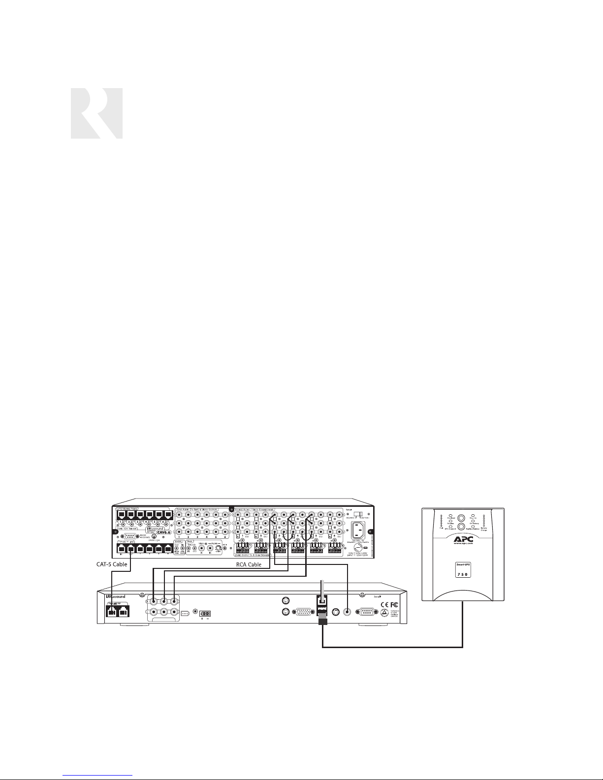
SMS3 Software Version 02.05.08 and higher
supports automatic shutdowns when used with
the APC Smart-UPS brand uninterruptible power
supplies. No configuration is necessary. Simply
connect the SMS3 to the APC Smart-UPS with a
USB cable. In the event of a power outage, the
UPS will continue to power the SMS3 until its battery life reaches a low level. At that point the
UPS will issue a command to the SMS3 via the
USB cable to initiate a graceful shutdown.
8
Sample configuration of SMS3 connection to APC Smart-UPS Power Supply
CAV6.6
SMS3
IN OUT
Smart Media Server
LINK
AUDIO OUTPUTS
POWER
IR I
N
+12VDC
6A MAX
1394
MOUSE
KEYBOARD
CRT VGA
CAT-5
CAT-5
RJ-45 cable
RJ-45 cable
LAN
USB 2.0/1.1
COMPOSITE
S-V
IDEO
VIDEO
RCA Composite
Video Cable and
Jumpers
RS232
INTERFACE
C
ASSEMBLED IN THE USA
SMS3 Media Server
US
NEWMARKET, NH
USB cable
APC Smart-UPS
Power Supply
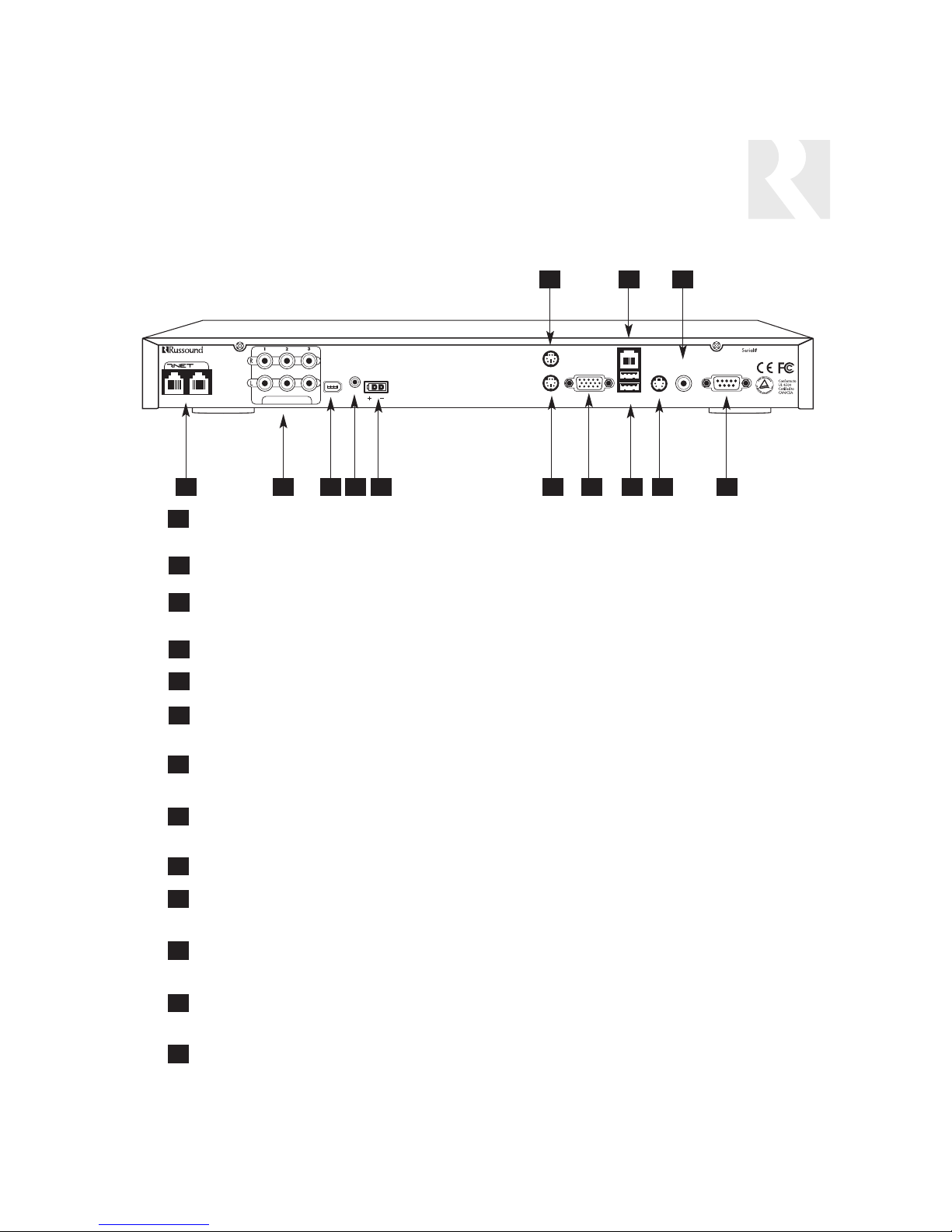
COMPONENT GUIDE
SMS3 REAR PANEL
RNET LINK IN/LINK OUT - Links to other Russound components that are RNET compatible
such as the CAV6.6 and CAM6.6
STREAM AUDIO OUTPUTS - Three line level audio signal outputs (RCA Cable)
1394 DATA TRANSFER PORT - Input/output connection for 1394A standard data transfers
such as external hard drives for backups
IR INPUT - IR control input
POWER SUPPLY - 12VDC external power supply connection
KEYBOARD PORT - PS/2 6-pin mini DIN connection for keyboard input
(recommended for diagnostics only)
MOUSE PORT - PS/2 6-pin mini DIN connection for mouse input
(recommended for diagnostics only)
CRT VGA CONNECTION - DB-15 connection for monitor output (cannot be used if either
S-video or composite video output are in use)
NETWORK CONNECTION - RJ-45 port for LAN connection
USB PORTS - Two USB input/output connections for USB 2.0/1.1 master devices (use for
backup devices only)
S-VIDEO - 4-pin S-video output connection (cannot be used if either VGA or composite video
output are in use)
COMPOSITE VIDEO - RCA jack for composite video output (composite video cable) (cannot
be used if either S-video or VGA output are in use)
RS-232 INTERFACE - DB-9 connection for RS-232 input/output communication with RS-232 devices
6
3
2
7
5
9
1
1 3 6 84 5
7
4
2
10 11
12
13
12
11
10
8
9
13
9
SMS3
Smart Media Server
LINK
IN OUT
AUDIO OUTPUTS
1394
POWER
N
IR I
+12VDC
6A MAX
MOUSE
KEYBOARD
CRT VGA
LAN
USB 2.0/1.1
COMPOSITE
S-V
IDEO
VIDEO
RS232
INTERFACE
US
C
ASSEMBLED IN THE USA
NEWMARKET, NH
VENTILATION REQUIREMENTS
IMPORTANT: The SMS3 should be situated so that its location or position does not interfere with its
proper ventilation. Do not block vents above or to the sides of the unit, as it requires ventilation to
the sides and above for proper operation. Do not expose to excessive dust, and do not allow dust to
build up on the unit and block vent holes. Do not place the SMS3 above a heat-generating component
such as an audio amplifier, and do not place a heat-generating component directly above the SMS3.
Be sure to leave at least 2 inches of space to the sides of the unit with open air flow
above. A single-space rack mount vent or about 1.75 inches must be kept clear above
the unit.
AUTOMATIC THERMAL SHUTDOWN
The SMS3 is equipped with a thermal threshold shut down that is activated through the server’s software. Excessive dust build-up on the internal heat sink can cause a shut down. If a thermal shut down
occurs, the unit will emit a warbled beep for five seconds, then will power off. If this occurs, do not
re-power the SMS3 until sufficient cooling time (at least 10 minutes) has passed. Check for proper
unit ventilation and remove any dust build-up with compressed air. If the unit is powered while temperatures are still above threshold, the SMS3 will repeat the beep and shut down again.
SMS3 INSTALLATION QUICK LOOK
1. Connect SMS3 to a controller amplifier (RNET controller Source Setup is command type PERIPHERAL)
2. Connect SMS3 to LAN
3. Connect SMS3 to video display
4. Connect SMS3 to an unswitched power supply
SMS3 LOCAL AREA NETWORK (LAN) CONNECTION QUICK LOOK
1. Connect SMS3 to a DHCP (Dynamic Host Configuration Protocol) router with NAT/Firewall.
2. Check LEDs on Ethernet connector (back of SMS3). A solid green light indicates a physical
network connection; a flashing yellow LED indicates network activity.
3. Obtain SMS3 IP address on LAN through video display (page 20)
4. From a computer networked on the same LAN, use a web browser to locate the SMS3
(IP address) on the LAN
TROUBLESHOOTING NETWORK PROBLEMS
1. Are the LEDs on the Ethernet connector (back of SMS3) illuminated?
If NO, troubleshoot cable and connection. This LED lights up when ANY network is connected.
2. What does the SMS3 report as its IP address (page 20)?
If no IP address appears, then DHCP is not working. Refer to router instructions.
INSTALLATION OPTIONS
OVERVIEW
10
11
INSTALLATION OPTIONS
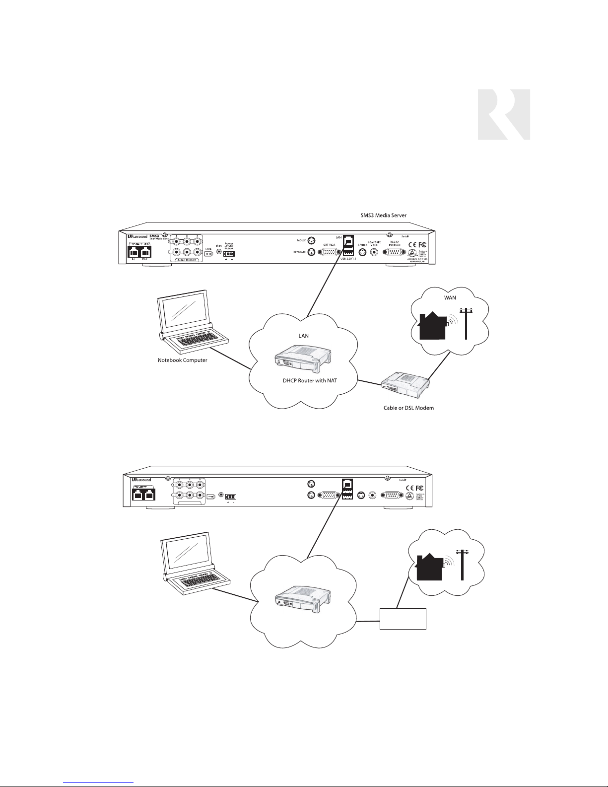
LAN WITH CABLE OR DIAL-UP MODEM
The diagram above shows a typical LAN connection for homes using a Cable or DSL modem to connect to the Internet. The SMS3 connects to the DHCP router with NAT/Firewall.
The diagram above shows a typical LAN connection for homes using a dial-up modem to connect to
the Internet. The SMS3 connects to the DHCP router with NAT/Firewall.
NOTE: For security reasons, it is REQUIRED that the SMS3 be connected to the internet behind a
DHCP router with NAT/Firewall. The router cannot be in bridge mode and the SMS3 cannot be placed
in the router’s DMZ.
SMS3 Media Server
IN OUT
SMS3
Smart Media Server
LINK
AUDIO OUTPUTS
POWER
N
IR I
+12VDC
6A MAX
1394
MOUSE
KEYBOARD
CRT VGA
LAN
USB 2.0/1.1
RS232
COMPOSITE
S-V
INTERFACE
IDEO
VIDEO
US
C
ASSEMBLED IN THE USA
NEWMARKET, NH
WAN
LAN
Notebook Computer
DHCP Router with NAT
MODEM

Distributed Video Signal
The SMS3 Smart Media Server uses a video display to show the graphical user interface during
operation. The SMS3 outputs one video signal
that is available in three formats - composite
video, S-video and VGA.
The SMS3 supports only one video output
format in use at any given time. For simultaneous video outputs, a commercial product that allows this should be used. An
example is the GrandTec GEZ-1000 USB 1.1
PC to Video Cable product, which supports
simultaneous composite, S-video and VGA
outputs.
To view the SMS3 interface, connect a video display (TV, display panel, etc.) directly to the SMS3
back panel using an S-video, composite video or
VGA connection. Another viewing option is connecting a computer monitor to the SMS3 15-pin
VGA connection on the rear panel.
There are several options available to distribute
the SMS3 video display.
With video distribution systems such as the
CAV6.6, the composite video signal must be
shared between all three streams (sources). The
CAV6.6 has a video signal output for each
source input that can be looped to the next input
with an RCA video patch cable.
For non-video distribution systems such as the
CAS44, an RF modulator and RF distribution
amplifier may be used as an alternate means of
distributing video to each room in the system.
With one video stream out, if there is more than
one video interface (TV, display) using the same
signal, all show the same view and all will update
at the same time. When a menu command is
received by the SMS3, the video signal will display the stream that was the target of the command.
Note: The video display is auto-sensing; it
is looking for a load on the composite or
S-video connection. If the video is connected after the SMS3 is powered, there will be
no signal, as the SMS3 default setting is
VGA output only. Simply reboot the SMS3
after connecting to a TV or video display,
and the video display will sense the load.
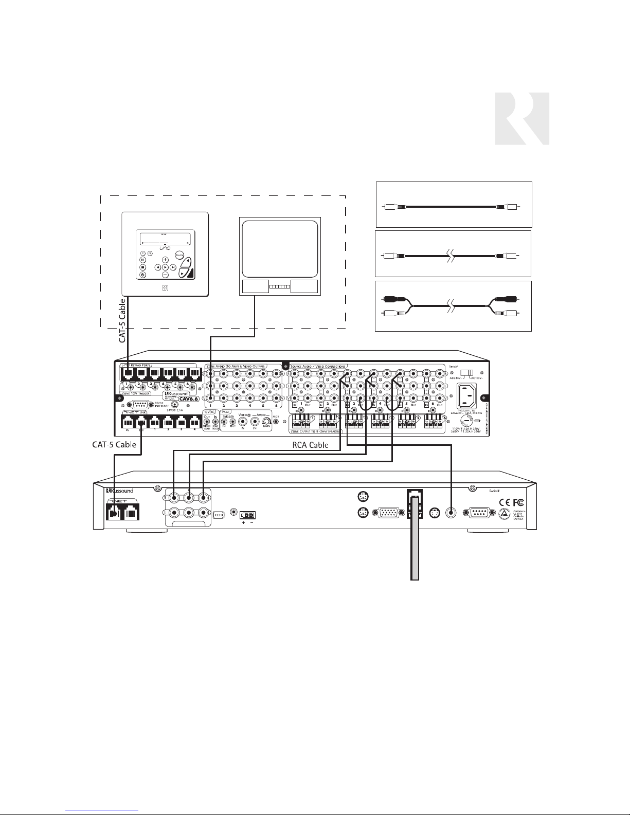
CAV6.6 With Distributed Video Signal
In a CAV6.6 system, the SMS3’s three streams
are configured as three sources, with command
type PERIPHERAL. Its composite video signal is
shared between all three sources by using an
RCA cable to loop the video from source out to
source in.
Refer to the diagram on the next
page for connections.
1. Connect the three RCA cables from the SMS3
three sources to the controller amplifier source
inputs. For RNET-enabled systems, SMS3 source
numbers are preconfigured:
SMS3 Stream 1=RNET Source 3
SMS3 Stream 2=RNET Source 4
SMS3 Stream 3=RNET Source 5
These source numbers can be re-configured from
the SMS3 if necessary.
2. Connect a CAT-5 patch cable from the CAV6.6
RNET Link Out port to the SMS3 RNET Link In port.
3. Using a straight-through Ethernet RJ-45 CAT-5
patch cable, connect from the SMS3 LAN port to
an open port on the network router.
4. Connect the composite video cable from the
SMS3 composite video port to the Source 3
video input.
5. Use an RCA loop cable to connect the
Source 3 video out to Source 4 video in. Loop
another cable from Source 4 video out to
Source 5 video in.
6. Connect an RCA cable from the video source’s
video in jack to the CAV6.6’s Zone Video Output.
INSTALLATION OPTIONS
VIDEO DISPLAY
12
13
Media Server
INSTALLATION OPTIONS
CAV6.6 WITH DISTRIBUTED VIDEO SIGNAL
CAV6.6 With Distributed Video Signal
Note: CAM6.6 installation is similar to CAV6.6 above but without video support. Please refer to
Page 14 for employing RF modulation to distribute video in non-video distribution systems.
UNO-S2
keypad
Zone 1
Composite Video Jumper
(2 recommended)
Composite Video Cable
(1 included)
RCA Cable
TV
(3 included)
RCA Composite
Video Cable
CAV6.6
RCA Composite
Video Cable and
Jumpers
IN OUT
SMS3
Smart Media Server
LINK
AUDIO OUTPUTS
1394
POWER
N
IR I
+12VDC
6A MAX
MOUSE
KEYBOARD
CRT VGA
LAN
USB 2.0/1.1
VIDEO
RS232
I
NTERFACE
C
ASSEMBLED IN THE USA
NEWMARKET, NH
COMPOSITE
S-V
IDEO
SMS3 Media Server
Ethernet CAT-5
RJ-45 patch cable
To L AN
US
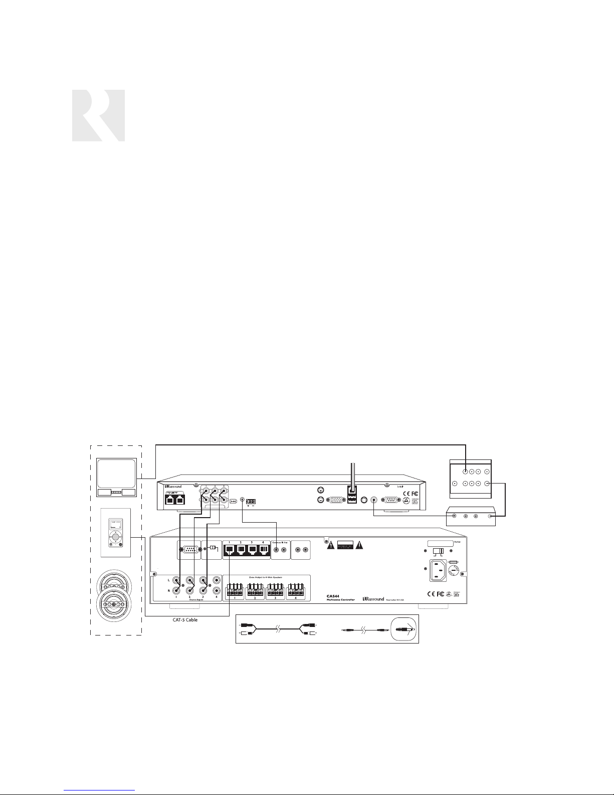
In multisource, non-video distribution systems such as
the CAS44, the SMS3’s three streams are configured
as three sources. To distribute the video signal, an RF
modulator and RF distribution amplifier may be used
as an alternate means of distributing video to each
room in the system.
The composite video out of the SMS3 is supplied to
an RF modulator to convert the signal to a specific
channel which the television tuners throughout the
home can receive, just like a TV station. An RF distribution amplifier will accept the RF modulator’s output,
amplify and distribute it to multiple outputs that can be
wired to each television through a coaxial cable such
as RG6. The television will need to be tuned to the
channel that the RF modulator is set for in order to
see the composite video signal output of the SMS3.
CAS44 Installation with RF Modulator
1. Using the three RCA cables, connect the SMS3’s
three source outputs to the controller amplifier source
inputs.
2. Using the IR link cable, connect the controller amplifier’s IR emitter port to the SMS3 IR In port.
3. Using a straight-through Ethernet RJ-45 CAT-5 patch
cable, connect from the SMS3 LAN port to an open
port on the network router.
4. Using a composite video cable, connect the SMS3
composite video port to the RF modulator video input.
5. Using coaxial cable (RG6), connect the RF modulator’s video output to the RF distribution amplifier modulator input.
6. Using coaxial cable (RG6), connect the RF distribution amplifier modulator’s TV output to the television’s
cable/antenna input.
Note: Some modulators are unable to be sensed by
the SMS3 during boot-up. In the event that you are
unable to get video through the modulator, boot up the
SMS3 with a TV connected to the Composite Video
Out. Once you have video on the TV, you can switch
over to the modulator.
INSTALLATION OPTIONS
CAS44 WITH RF MODULATED DISTRIBUTED VIDEO SIGNAL
CAS44 Controller With RF Modulated Distributed Video Signal
14
RCA Coaxial Cable (RG6)
ZONE 1
SMS3
TV
MSvr1
Source
KPL
Speakers
IN OUT
RCA Cable
LINK
RS232 Interface
Smart Media Server
AUDIO OUTPUTS
Update Run
CPU Keypad Ports
1394
POWER
N
IR I
+12VDC
6A MAX
IR Link Cable
RCA Cable IR Link Cable
To LA N
MuteInTrigger
12VDC
100mA Max
KEYBOARD
Out
MOUSE
LAN
CRT VGA
USB 2.0/1.1
CAUTION
WARNING: SHOCK HAZARD – DO NOT OPEN.
AVIS: RISQUE DE CHOC ELECTRIQUE – NES PAS OVRIR.
SMS3 Media Server
RS232
COMPOSITE
I
NTERFACE
VIDEO
IDEO
S-V
RCA Composite Video Cable
Pos (+)
Neg (–)
US
C
ASSEMBLED IN THE USA
NEWMARKET, NH
AC240V~
100-120V~3A,
220-240V1.25A,
50-60Hz
Designed in USA Made in Taiwan
CAS44 Controller
CATV
TV OUTPUT
INPUT
RF Distribution Amp
AUDIO
VIDEO
AUDIO
L
INPUT
RF Modulator
AC110V~
110V/F3.0A H 250V
240V/T1.25A H 250V
R
MOD
INPUT
OUTPUT
RCA
Coaxial
Cable
(RG6)
 Loading...