

Ratio
®
High-Effi ciency Indoor Loudspeakers
Instruction Manual
2
INTRODUCTION
Product Description
Russound Ratio® High-Effi ciency Loudspeakers are
designed to provide high acoustic output with low
amplifi er power. This makes them perfectly suited for
use with low- powered amplifi ed keypads and amplifi ed
volume controls.
Low-mass driver materials and state-of-the-art engineering allow these speakers to produce higher sound
pressure levels than conventional speakers without
sacrifi cing sound quality.
When ordinary speakers are used with low-powered
amplifi ed keypads, they have limited output. This is
because the speakers are designed to handle higher
power levels from other types of amplifi ers. Because of
their high effi ciency, Ratio speakers play more loudly
than conventional speakers when used with amplifi ed
keypads.
Ratio speakers are designed to reduce installation time.
All models incorporate an innovative spring-clip mounting feature that makes them easier to install. Also, the
ceiling speakers have preinstalled grilles. These features
allow the installer to simply connect the speaker cables
and press the speakers into the ceiling for a quick
installation.
Caution
Ratio speakers are for use only with amplifi ed
keypads and volume controls or amplifi ers
with a power output of up to 20 watts per
channel. Do not use Ratio speakers with
receivers or amplifi ers rated at more than 20
watts per channel.
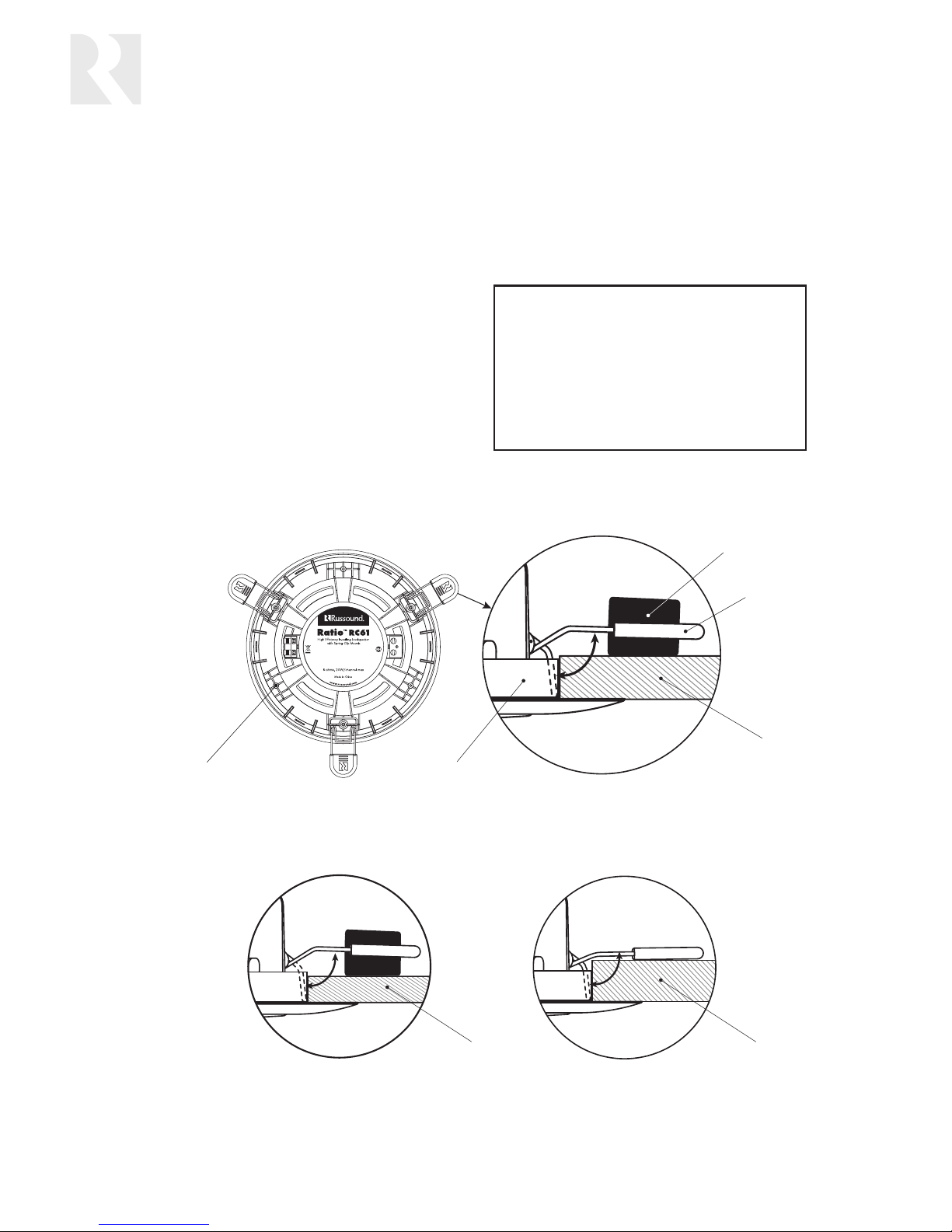
Spring clip
Spacer
5/8” (1.6 cm) ceiling
Mounting ringBoss for seismic restraint screw
1/2” (1.3 cm) ceiling 3/4” (1.9 cm) ceiling
Bosses opposite the spring clips on ceiling speakers can be used to attach seismic restraints.
Spacers on the spring clips are factory set for a 5/8” (1.6 cm) ceiling or wall thickness.
The spring clip spacers can be inverted to accommodate a ceiling or wall thickness of 1/2” (1.3 cm)
or removed for a 3/4” (1.9 cm) ceiling or wall, or when rough-in brackets are used.
3
INTRODUCTION
Applications
Ratio speakers provide room-fi lling sound in any
multiroom system with amplifi ed keypads. In many
cases where an external amplifi er would be added for
conventional speakers, a pair of Ratio speakers powered
directly by the keypad will suffi ce.
Designed for optimal performance with amplifi ed keypad systems, Ratio speakers make it possible to use such
systems in places where higher-powered systems would
otherwise be used. This provides an economical alternative to high-powered multiroom systems.
Speaker Placement
Following are some general placement guidelines for
stereo listening and background music applications.
Other things to consider for speaker placement include:
• Locations of unobstructed wall or ceiling cavities in
which to mount the speakers
• Accessibility for running cables through the walls or
ceilings to the speaker locations
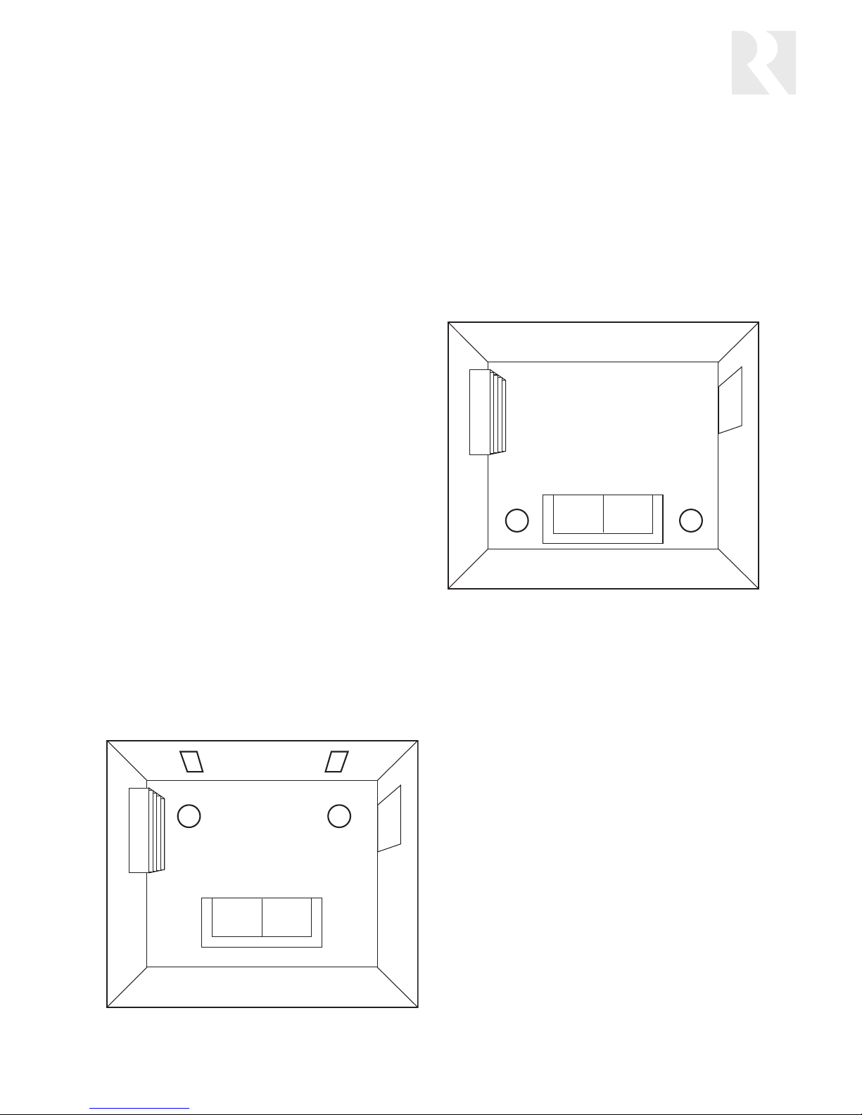
Stereo music listening
Speaker placement for stereo music listening is important for proper imaging. Imaging is the ability of the
speaker pair to reproduce sounds so they appear to
come from between the speakers.
In a stereo music system, we recommend placing the
left and right speakers about 60 degrees apart when
viewed from the center listening position. In-wall
speakers should be centered at ear level.
Background music
Speaker placement for background music is less critical
than for stereo listening. Often the goal is to provide
even coverage throughout the room, without regard to
a fi xed listening position. In this case, the speakers can
be placed so they cover equal portions of the room.
In other cases, the goal is to provide background music
only in part of a large room or open area, often where
the seating is located. In this case, the speakers can be
located to provide coverage in that part of the room.
Placement near corners
Placing the speakers near the corners of a room can
help emphasize bass frequencies. This is fi ne if both
speak ers in a stereo pair are mounted near corners, but
avoid placing one speaker in a corner and another in a
large open area.
The best acoustic performance will result if the speakers
face the same type of surface and are placed in similar
positions on the same type of wall or ceiling surface.
Small rooms
The RC61S stereo ceiling speaker is useful for providing
coverage for a small room from a single point. Usually it
should be placed near the center of the room.
Avoid wet locations
Ratio indoor speakers are designed to provide reliable
long-term service as long as they are not installed
in wet or damp locations such as showers. Also, they
should not be installed in areas continually subject to
high humidity, such as unventilated bathrooms and
porches in humid climates.
Speaker placement for background music
in a seating area
Speaker placement for stereo listening

4
PREPARATION
Prewiring
Run a separate 2-conductor stranded copper speaker
cable of at least 16 AWG (1.5 mm) from the amplifi ed
keypad or amplifi er to each speaker. (Note: When using
the RC61S stereo ceiling speaker, run either one 4-conductor cable or two 2-conductor cables to the speaker.)
Be sure to use cable with the appropriate fi re resistance
rating for the application. Check the local building
code for specifi c requirements. Russound offers 2- and
4-conductor speaker cables with a Class 3 fi re rating for
in-wall installation.
When running a speaker cable parallel to an AC power
cable, keep them at least 12 inches (30 cm) apart to
minimize electromagnetic interference. If the speaker
cables must cross AC wiring, cross them at right angles.
Leave about 2 feet (0.6 m) of cable at the keypad or
amplifi er end for connecting to the output terminals.
Label the cables so you will know which cable connects
to each channel. At each speaker location, leave enough
cable so that at least 2 feet (0.6 m) can extend through
the cutout for connecting to the speaker.
Cutting Holes in Existing Wallboard
Note: Ratio speakers are designed to mount to ceiling
and wall material between ½ inch (1.3 cm) and ¾ inch
(1.9 cm) thick. Spacers on the spring clips accommodate
varying thicknesses of material within this range.
1. Once you have determined roughly where to place
the speakers, use a stud fi nder to locate the wall
studs or ceiling joists and mark their location.
2. Check to make sure there are no obstructions such as
electrical cables, water pipes, or heating ducts where
you want to put the speakers.
3. Position the provided cutout template on the wall or
ceiling and trace around it with a pencil to draw the
outline of the cutout.
4. Score the outline with a utility knife to prevent chipping or tearing. Then use a drywall saw or spiral-cut
tool to cut the hole. Make sure you don’t make the
hole any larger than the template.
Installing Rough-In Brackets
If the walls and ceilings are not yet in place, you can
use Russound rough-in brackets to mark the speaker
locations and provide templates for making the cutouts.
Nail or screw the wings of the rough-in bracket to the
ceiling joists or wall studs, with the opening between
them where you want the speaker to be. The drywall
installer can then use the bracket as a template to cut
the hole in the wallboard exactly the same size as the
bracket ring.
Painting the Speakers
The speaker frames and grilles can be painted to match
the room décor. Be sure not to get paint on the speaker
baffl es or drivers.
1. Gently pull off the speaker grilles, making sure not to
distort them. To remove the grilles from the ceiling
speakers, fi rst unbend the retainer tabs on the edges
of the grilles. Remove the scrim cloths from inside
the grilles and set them aside for reassembly.
2. Mask the baffl es (the areas inside the frames that
house the drivers) with the provided paint shields. If
you will be spraying the frames, also mask the back
of the speakers to keep overspray off the drivers.
3. Paint the frames and grilles separately. Spraying is
ideal, but if you can’t spray the paint, a roller with a
short or medium nap will work better than a brush.
4. While the paint is still wet, clear any clogged holes in
the grilles with bursts of compressed air.
5. After the paint has thoroughly dried, remove the
masking.
The cardboard template supplied with each speaker has perforations for the cutout and a paint shield

5
INSTALLATION
Connecting the Speakers
Note: Before connecting a ceiling speaker, place the mounting ring, fl ange down, around the back of the speaker.
1. Strip 1 to 2 inches (2.5 to 5 cm) off the end of the cable’s outer jacket. Then strip ½ inch (1.3 cm) of insulation off
each wire.
2. Twist the wire strands together so there are no strands separated from the bundle.
3. Connect the wires to the speaker terminals, being sure to observe proper polarity. For standard speaker cable with
red and black wires, connect the red wire to the red positive (+) terminal and the black wire to the black negative
(–) terminal.
Note: Some speaker cables have other ways of designating polarity. For example, cable with a clear jacket usually
has a copper-colored wire for positive and a silver-colored wire for negative. In a cable with white and black wires,
the white is positive and the black is negative. Cable with both wires the same color may have grooves, ribs, or
stripes on the positive wire.
4. Check to make sure there are no stray strands of wire outside the terminals. If there are, remove the wire, twist
the strands together, and reconnect the wire to the terminal.
Speaker cable connections
GrilleBaffleMounting ring Scrim clothFrame
GrilleScrim clothBaffleFrame
In-ceiling and in-wall speaker assemblies

6
Final Assembly
Ceiling speakers
Reattach grille
1. If you removed the grille for painting, insert the scrim cloth into the grille and align the tabs on the edge of the
grille with the slots in the baffl e.
2. Gently press the grille back into place on the speaker, using even pressure around the edge. Don’t press in the
center of the grille.
3. Bend the retainer tabs toward the center of the speaker to secure the grille in place.
Install speaker in cutout
Note: The spring clip spacers are set at the factory for a ceiling thickness of 5/8 inch (1.6 cm). For a 1/2 inch (1.3 cm)
ceiling, turn the spacers over so the thicker side faces the ceiling. Remove the spacers from the clips for a 3/4 inch
(1.9 cm) ceiling, or when using rough-in brackets.
Note: Make sure the mounting ring is placed fl ange down around the back of the speaker.
1. If you are using a seismic restraint, pass it through the mounting ring and attach it with a screw to one of the
bosses opposite the spring clips. Flip the spring clips so they point straight up.
2. Place the mounting ring so it rests on the wires of the spring clips.
3. Make sure there is no obstruction around the edge of the cutout to keep the spring clips from fl ipping down to
hold the speaker in place.
4. Center the back of the speaker in the cutout and push it straight in until the spring clips fl ip down and the
speaker is secure.
Note: Push only on the frame, not on the grille.
Cutout
Mounting ring
Speaker
Wallboard
Ceiling joists
Spring clip
INSTALLATION
Ceiling speaker installation

7
Wall speakers
Note: The spring clip spacers are set at
the factory for a wall thickness of 5/8
inch (1.6 cm). For a 1/2 inch (1.3 cm)
wall, turn the spacers over so the thicker
side faces the wall. Remove the spacers
from the clips for a 3/4 inch (1.9 cm)
wall, or when using rough-in brackets.
1. If you haven’t already removed the
grille for painting, gently pull it off
along with the scrim cloth.
2. On the back of the speaker, fl ip the
spring clips so they point straight
back. Also make sure the dog-leg
clamps are swiveled inward.
3. Make sure there is no obstruction
around the edge of the cutout to keep
the spring clips from fl ipping forward.
4. Center the back of the speaker in the
cutout and push it straight in until the
spring clips fl ip forward. Push only on
the frame, not on the drivers.
Note: If the cutout is too large, one or
both spring clips might not fl ip forward.
Make sure both clips grab the wallboard
before you release the speaker.
5. Level the speaker. Turn the clamp
screws clockwise until the clamps are
drawn up snugly, securing the speaker.
Tighten the screws equally but don’t overtighten them.
6. Insert the scrim cloth into the grille and press it into place on the speaker, using even pressure around the edge.
Connecting the Amplifi ed Keypad or Amplifi er
1. Make sure the keypad or amplifi er is turned off.
2. Strip 1 to 2 inches (2.5 to 5 cm) off the end of each cable’s outer jacket. Then strip just enough insulation off
each wire to allow inserting the wires fully into the keypad’s or amplifi er’s speaker terminals.
3. Twist the wire strands together so there are no strands separated from the bundle.
4. Connect the wires to the speaker terminals, being sure to observe proper polarity.
5. Check to make sure there are no stray strands of wire outside the terminals. If there are, remove the wire, twist
the strands together, and reconnect the wire to the terminal.
Taking Care of Your Speakers
Your speakers are made of durable materials that need very little care. All we recommend is an occasional dusting
with a soft cloth or light vacuuming with a dust brush attachment. If you vacuum the speakers, leave the grilles in
place to avoid damaging the drivers. Do not use any harsh detergents, chemical solvents, or abrasive materials on
your speakers.
Dog-leg clamp
Spring clip
GrilleSpeaker
Cutout
Wallboard
Wall studs
INSTALLATION
Wall speaker installation

8
Model: RC61
Loudspeaker type: Round 2-way in-ceiling
Woofer: 6.5” (16.5 cm) polypropylene cone
Tweeter: ½” (13 mm) polyetherimide dome
Frequency response: 76 Hz – 20kHz ±3 dB
Frequency range: 58 Hz – 20kHz –6/+3 dB
Sensitivity: 90 dB SPL 2.83 V @ 1 m
Nominal impedance: 8 ohms
Recommended amplifi er power: 3–20 watts RMS
Cable connector: Spring terminal block
Overall diameter: 9.8” (24.9 cm)
Cutout diameter: 8.38” (21.3 cm)
Mounting depth: 2.8” (7.1 cm)
Weight: 2.7 lb (1.2 kg)
Finish: White (paintable)
SPECIFICATIONS
Model: RC61S
Loudspeaker type: Round 2-way single-point stereo
in-ceiling
Woofer: 6.5” (16.5 cm) polypropylene cone,
dual voice coil
Tweeters: (2) ½” (13 mm) polyetherimide domes
Frequency response: 70 Hz – 20kHz ±3 dB
Frequency range: 53 Hz – 20kHz –6/+3 dB
Sensitivity: 93 dB SPL 2.83 V @ 1 m
Nominal impedance: 8 ohms per channel
Recommended amplifi er power: 3–20 watts RMS
Cable connectors: (2) Spring terminal blocks
Overall diameter: 9.8” (24.9 cm)
Cutout diameter: 8.38” (21.3 cm)
Mounting depth: 2.8” (7.1 cm)
Weight: 2.7 lb (1.2 kg)
Finish: White (paintable)

9
SPECIFICATIONS
Model: RC81
Loudspeaker type: Round 2-way in-ceiling
Woofer: 8” (20.3 cm) polypropylene cone
Tweeter: ½” (13 mm) polyetherimide dome
Frequency response: 71 Hz – 20kHz ±3 dB
Frequency range: 53 Hz – 20kHz –6/+3 dB
Sensitivity: 92 dB SPL 2.83 V @ 1 m
Nominal impedance: 8 ohms
Recommended amplifi er power: 3–20 watts RMS
Cable connector: Spring terminal block
Overall diameter: 11.3” (28.7 cm)
Cutout diameter: 9.88” (25.1 cm)
Mounting depth: 3.4” (8.6 cm)
Weight: 3.2 lb (1.5 kg)
Finish: White (paintable)
Model: RW691
Loudspeaker type: Rectangular 2-way in-wall
Woofer: 6” x 9” (15.2 x 22.9 cm)
polypropylene cone
Tweeter: ½” (13 mm) polyetherimide dome
Frequency response: 64 Hz – 20kHz ±3 dB
Frequency range: 46 Hz – 20kHz –6/+3 dB
Sensitivity: 90 dB SPL 2.83 V @ 1 m
Nominal impedance: 8 ohms
Recommended amplifi er power: 3–20 watts RMS
Cable connector: Spring terminal block
Overall dimensions: 8.2” W x 12.2” H
(20.8 x 31.0 cm)
Cutout dimensions: 6.75” W x 10.75” H (17.1 x 27.3 cm)
Mounting depth: 3.6” (9.1 cm)
Weight: 3.6 lb (1.6 kg)
Finish: White (paintable)

10
NOTES

11
WARRANTY
Warranty
Russound Ratio Loudspeakers have a fi ve-year warranty against defects in materials and workmanship. During the warranty period,
Russound will replace any defective part and correct any defect in workmanship without charge for either parts or labor.
Russound may replace returned speakers with a product of equal value and performance. In such cases, some modifi cations to the
mounting may be necessary and are not Russound’s responsibility.
For this warranty to apply, the speaker must be installed and used according to its written instructions. If repairs are necessary,
they must be performed by Russound. The speaker must be returned to Russound at the owner’s expense and with prior written
permission. Proof of purchase must accompany all claims. Accidental damage and shipping damage are not considered defects,
nor is damage resulting from abuse or from servicing performed by an agency or person not specifi cally authorized in writing by
Russound.
This warranty does not cover:
• Damage caused by abuse, accident, misuse, negligence, or improper operation or installation.
• Products that have been altered or modifi ed.
• Any product whose identifying number or serial number has been altered, defaced, or removed.
• Normal wear and maintenance.
Damage to or destruction of components due to application of excessive power voids the warranty on those parts. In these cases,
repairs will be made on the basis of the retail value of the parts and labor. To return for repairs, the speaker must be shipped to
Russound at the owner’s expense, along with a note explaining the nature of service required. Be sure to pack the speaker in a corrugated container with at least 3 inches of resilient material to protect the speaker from damage in transit.
Before returning a speaker for repair, call Russound at 603.659.5170 for a Return Authorization number. Write the RA number on
the shipping label and ship to: Russound, ATTN: Service, 5 Forbes Road, Newmarket NH 03857.
Russound sells products only through authorized Dealers and Distributors to ensure that customers obtain proper support and
service. Any Russound product purchased from an unauthorized dealer or source, including retailers, mail order sellers and online
sellers will not be honored or serviced under existing Russound warranty policy. Any sale of products by an unauthorized source or
other manner not authorized by Russound shall void the warranty on the applicable product.

Ratio
®
High-Effi ciency Indoor Loudspeakers
Instruction Manual
Models
RC61
RC61S
RC81
RW691
Russound
5 Forbes Road, Newmarket NH 03857 USA
Tel 603.659.5170 • Fax 603.659.5388
www.russound.com
Technical Support: tech@russound.com 28-1269 Revision 1 12/14/07
Copyright © 2007 Russound. All rights reserved. All trademarks are the property of their respective owners. Specifi cations are subject to
change without notice. Russound is not responsible for typographical errors or omissions.
 Loading...