

Page 1
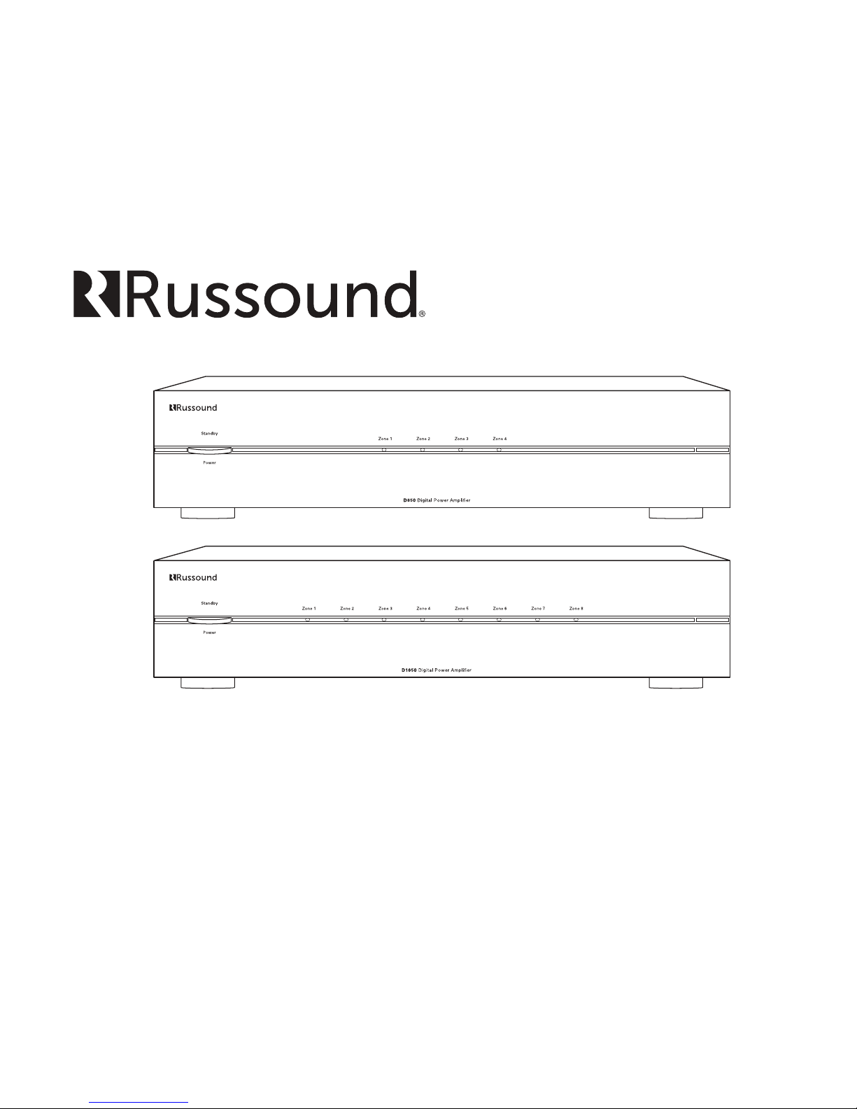
D850, D1650
Multichannel Digital Power Ampliers
Installation Manual
D850
D1650
Page 2
2 Russound D850, D1650 Installation Manual
The lightning ash with arrowhead symbol,
within an equilateral triangle, is intended to alert
the user to the presence of uninsulated dangerous
voltage within the product’s enclosure that may
be of sucient magnitude to constitute a risk of electric
shock to persons.
The exclamation point within an equilateral
triangle is intended to alert the user to
the presence of important operating and
maintenance (servicing) instructions in the
literature accompanying the appliance.
Safety Instructions
1.
Read Instructions - All the safety and operating instructions
should be read before the appliance is operated.
2. Retain Instructions - The safety and operating instructions
should be retained for future reference.
3. Heed Warnings - All warnings on the appliance in the
operating instructions should be adhered to.
4. Follow Instructions - All operating and user instructions
should be followed.
5. Water and Moisture - The appliance should not be used near
water; for example, near a bathtub, washbowl, kitchen sink,
laundry tub, in a wet basement, or near a swimming pool.
The apparatus shall not be exposed to dripping or splashing
liquids and no objects lled with liquids, such as vases, shall
be placed on the apparatus. Do not touch the appliance
with wet han ds. Do not handle the a ppliance or power cord
with wet or damp hands. If water or any other liquid enters
the appliance cabinet, t ake it to qualied service personnel
for inspec tion.
SAFETY INSTRUCTIONS
6. Cleaning - The appliance should be cleaned only as
recommended by the manufacturer. From time to time you
should wipe o the front and side panels and the cabinet
with a soft cloth. Do not use rough material, thinners, alcohol
or other chemical solvents or cloths since this may damage
the nish or remove the panel lettering.
7. Ventilation - The appliance should be situated so that
its location or position does not interfere with its proper
ventilation. For example, the appliance should not be
situated on a bed, sofa, rug, or similar surface that may
block the ventilation openings, or placed in a built-in
installation, such as a bookcase or cabinet that may impede
the ow of air through the ventilation openings. Place the
unit in a well-ventilated location, leaving at least 2 inches
(5 cm) of clearance on all sides, top and rear of unit for air
ow. If ventilation is blocked, the unit may overheat and
malfunction.
8. Heat - The appliance should be situated away from heat
sources such as radiators, heat registers, stoves, or other
appliances (including ampliers) that produce heat.
9. Grounding or Polarization - Precaution should be taken so
that the grounding or polarization means of an appliance is
not defeated.
10. Power Cord Protection - Power supply cords should be
routed so that they are not likely to be walked on or pinched
by items placed upon or against them, paying particular
attention to cords at plugs, receptacles, and the point where
they exit from the appliance.
11. Power Sources - The appliance should be connected to a
power supply only of the type described in the operating
instructions or as marked on the appliance.
12. Main Power Disconnect - The power switch is a single-pole
switch. When the switch is in the “O” position, the appliance
is not completely disconnected from the main power. The
main power plug is used as the disconnect device and shall
remain readily operable. When installing the product, ensure
that the plug is easily accessible.
13. Non-Use Periods - The power cord of the appliance should
be unplugged from the outlet when left unused for a long
period of time.
14. Attachments - Only use attachments/accessories specied
by the manufacturer.
15. Carts and Stands - The appliance should
be used only with a cart or stand that is
recommended by the manufacturer. An
appliance and cart combination should be
moved with care. Quick stops, excessive
force and uneven surfaces may cause the appliance and cart
combination to overturn.
16. Wall or Ceiling Mounting - The appliance should be
mounted to a wall or ceiling only as recommended by the
manufacturer.
17. Location of the Amplier - Do not mount this unit under a
kitchen cabinet. Do not expose the amplier to direct sun
light or heating units as the amplier internal components’
temperature may rise and shorten the life of the components.
Avoid damp and dusty places.
18. Object and Liquid Entry - Care should be taken so that
objects do not fall and liquids are not spilled into the
enclosure through the openings.
19. Servicing - The user should not attempt to service the
appliance beyond that described in the operating
instructions. All other servicing should be referred to
qualied service personnel.
20. Damage Requiring Service - The appliance should be
serviced by qualied service personnel when: A. The power
supply cord or the plug has been damaged; B. Objects have
fallen, liquid has been spilled into the appliance; C. The
appliance has been exposed to rain; or D. The appliance does
not appear to operate normally; or E. The appliance has been
dropped or the enclosure is damaged.
CAUTION: TO REDUCE THE RISK OF ELECTRIC
SHOCK, DO NOT REMOVE THE COVER. NO USERSERVICEABLE PARTS INSIDE. REFER SERVICING
TO QUALIFIED SERVICE PERSONNEL.
WARNING: TO REDUCE THE RISK OF FIRE
OR ELECTRIC SHOCK, DO NOT EXPOSE THIS
APPLIANCE TO RAIN OR MOISTURE.
Note: This equipment has been tested and found to comply with the
limits for a Class B digital device, pursuant to part 15 of the FCC rules.
These limits are designed to provide reasonable protection against
harmful interference in a residential installation. This equipment
generates, uses and can radiate radio frequency energy and, if not
installed and used in accordance with the instructions, may cause
harmful interference to radio communications. However, there is no
guarantee that interference will not occur in a particular installation. If
this equipment does cause harmful interference to radio or television
reception, which can be determined by turning the equipment o and
on, the user is encouraged to try to correct the interference by one of
or more of the following measures: reorient or relocate the receiving
antenna; increase the separation between the equipment and
receiver; connect the equipment into an outlet on a circuit dierent
from that to which the receiver is connected, or consult the dealer or
an experienced radio/TV technician for help.
This Class B digital apparatus complies with Canadian ICES-003.
Cet appareil numérique de la classe B est conforme à la norme NMB003 du Canada.
Page 3
3
Russound D850, D1650 Installation Manual
Introduction
The Russound D850 and D1650 multichannel digital ampliers are ideal for
use in adding additional power in distributed audio systems. The D850 provides
8 channels of digital amplication while the D1650 provides 16 channels. The
channels of both models are arranged in pairs to provide amplication for
stereo zones. Both models provide an array of useful features such as bridge
mode operation, global and independent zone triggering, audio sense circuitry
with adjustable delays per zone, a Bus Input and independent line inputs per
zone to meet a wide variety of applications and congurations.
Both models are rated at 50 watts per channel into 8 ohms and 80 watts
per channel into 4 ohms. With the stereo/Bridge Mono switch in the Bridge
position, channels are combined for a higher powered mono output of 160
watts into 8 ohms. The use of advanced digital amplication circuitry results
in a smaller, lighter chassis, with cooler operation than our previous amplier
models.
PRODUCT OVERVIEWTABLE OF CONTENTS
Thermal Protection
All Russound ampliers are designed with special circuitry to safeguard the
amplier under a thermal overload condition. Thermal protection mode can
only engage when the unit has been run at high volume for extended periods
of time without adequate ventilation and/or when speaker impedances are
below the minimum levels for the amplier.
Protection Circuitry
All Russound ampliers are designed with special circuitry to safeguard the
amplier under a short-circuit condition. A faulty speaker can also cause a
short circuit condition. The Zone LED will blink rapidly between Red and Blue
when the Zone is in short circuit protection.
The amplier will auto-correct itself when the trouble condition has been
removed. The amplier will then resume normal operation.
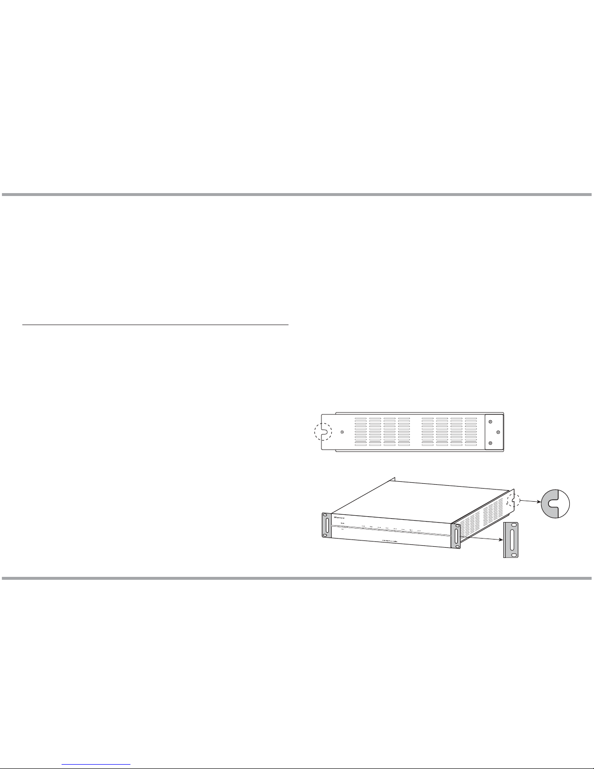
Rack Mounting
Both ampliers can be rack mounted using the included rack-mount ears and
hardware to attach the ears to the amplier. The amplier will take two rack
spaces with the feet removed.
Side View
FrontBack
Safety Instructions ..................................................................................................................2
Product Overview ...................................................................................................................3
Front and Back Panel Features ........................................................................................ 4-6
Typical System Conguraton .............................................................................................. 7
Bridge Mode Operation ........................................................................................................8
Using Signal Sensing ............................................................................................................. 9
Technical specications ......................................................................................................10
Troubleshooting ...................................................................................................................11
Limited Warranty ...................................................................................................................12
Page 4
4 Russound D850, D1650 Installation Manual
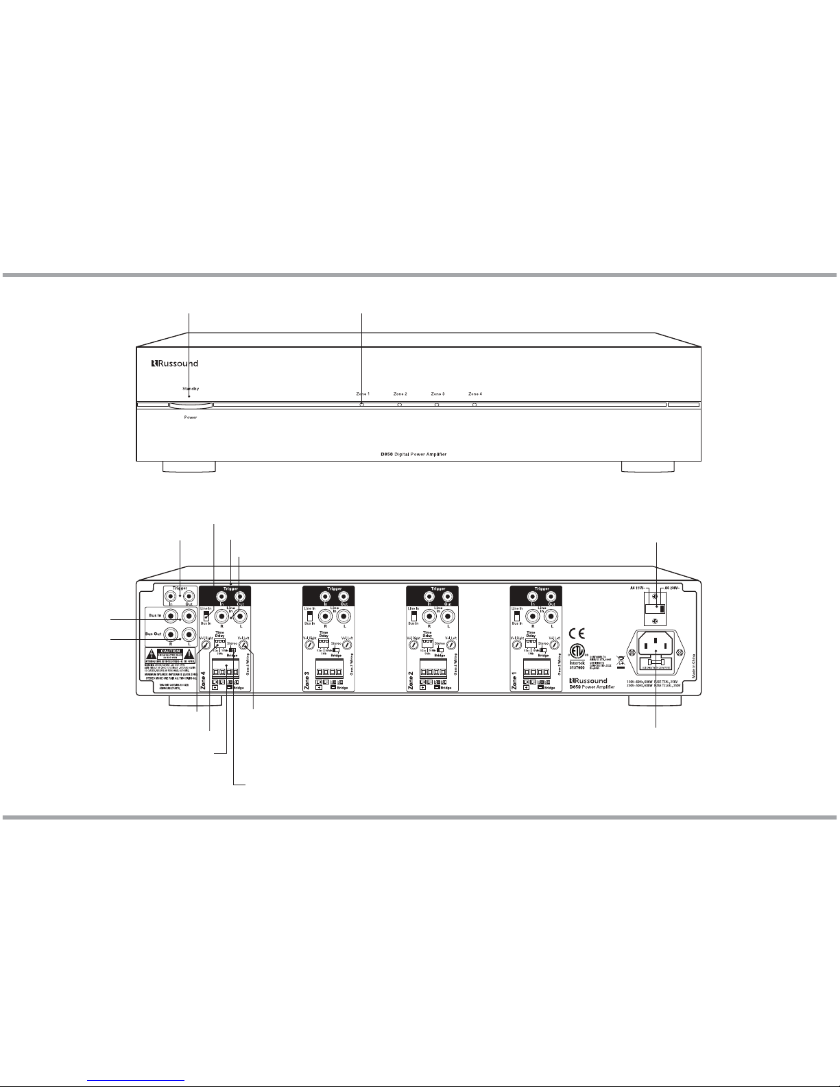
FRONT AND BACK PANEL
Speaker Outputs
Line Input
Delay Time
Line/Bus Switch
Zone 12VDC Trigger In/Out
Bus 12VDC Trigger In/Out
Bus In
Bus Out
Gain Control Right
Gain Control Left
Stereo/Bridge
Mono Switch
Note: the Gain control for each
speaker is on the opposite side
of the speaker connection.
AC Voltage Switch
D850 Rear Panel
D850 Front Panel
Zone LED
Power / Standby LED
AC Input
Page 5

5
Russound D850, D1650 Installation Manual
FRONT AND BACK PANEL
Speaker Outputs
Line Input
Delay Time
Line/Bus Switch
Zone 12VDC Trigger In/Out
Bus 12VDC Trigger In/Out
Bus In
Bus Out
Note: the Gain control for each
speaker is on the opposite side
of the speaker connection.
Stereo/Bridge
Mono Switch
AC Voltage Switch
D1650 Rear Panel
D1650 Front Panel
Zone LED
Power / Standby LED
AC Input
Gain Control Right
Gain Control Left
Page 6

6 Russound D850, D1650 Installation Manual
BACK PANEL FEATURES
Power/Standby LED
This LED lights red when any zone is active or the amplier is in standby mode.
Zone LED
When a zone is powered on, the corresponding LED lights blue. When a zone
is OFF, the LED is o (standby mode). If a short circuit happens on the speaker
outputs, the LED will blink fast red and blue.
Bus 12VDC Trigger In/Out
The Bus 12VDC Trigger In is used to activate all zones that are using the Bus
Input and disables other zone triggers or signal sensing on those zones when
it is used. When the Bus 12VDC Trigger is used, all Bus-controlled zone LEDs
will be blue and active.
If the Bus Trigger In has 12V applied to it, only the 12V Bus Trigger Out will
have 12V and the Zone Trigger Outputs will not.
Bus Input/Output
The bus line input is an optional input that can be used to connect a single
source to multiple zones. The bus line output is a passive passthrough of the
Bus Input and can be used to daisy chain the source to other ampliers in the
system.
Line Input
The line audio input for each zone is a dedicated sensing input that will
activate the zone when an audio signal from a source is present.
Line/Bus Switch
Sets the zone input to the Line Input or the Bus Input.
Speaker Outputs
The minimum speaker impedance is 4 ohms for Stereo Mode and 8 ohms for
Bridge Mode.
Gain Controls
Left and Right gain controls independently adjust the sound level for each
channel. When used in Bridge Mode only the Left control is used.
Power Switch
Turns the amplier on/o. This switch does not disconnect the main power
feed from the amplier; to disconnect the main power, the power cord must
be unplugged from the outlet.
Fuse Receptacle
Holds a replaceable fuse for AC power input connection. Refer to the
specications on page 10 for the fuse ratings.
AC Input / Voltage Switch
Voltage is set with a selectable switch for 115V or 230V operation. The AC
voltage input for the North American model is 115VAC at 60Hz (International
model, 230VAC at 50Hz). This receptacle accepts a 3-prong IEC C14 type
connector. A detachable 3- terminal power cord is included. The international
models include power cords for the UK, Europe, and Australia.
Zone 12VDC Trigger In/Out
The Zone 12V Trigger In is used to activate a specic zone. The Zone Trigger
Out can be used to trigger other 12V devices. The delay and audio sensing are
bypassed when the 12V Zone Trigger Input is used. When a Zone Trigger is
active, the zone LED will be blue. If no voltage is present in the Zone Trigger, the
Zone LED will be o.
Standby
Standby delay can be adjusted to either 5 seconds, 5 minutes, or 10 minutes
by using the DIP switches on the rear panel. This delay is selectable per zone.
When an audio signal is not present, the amplier will automatically go into
standby mode after the preset period of time.
The default position for the DIP switch is a 5-second delay. The time delay is
selected by moving the DIP switch to the down position.
Note: One and only one DIP switch must be in the Down position at any time.
Activating more than one DIP switch can lead to erratic audio operation.
Standby Mode
The amplier will go into Standby mode when audio signal or trigger is
not present, and after the minimum delay time has timed out. The amplier
consumes 0.5 Watt or less current while in standby power mode.
Stereo/Bridge Mono Switch
Sets each zone amplier for stereo or Bridge mono operation.
Compatibility with autoformer-based volume controls
The D850 and D1650 ampliers have been tested to work with all Russound
autoformer-based volume controls.
In order to use the D-series ampliers with auto-former based volume controls,
please refer to the Tech Tip on the Russound Dealer Portal titled “Using a D-Series
amplier with autoformer-based volume controls”.
This illustration shows the
DIP switch congured for a
5 second delay.
Page 7

7
Russound D850, D1650 Installation Manual
TYPICAL SYSTEM CONFIGURATION
Connections for audio distribution preamp outputs
Both the D850 and the D1650 can be congured as the main amplier for an
audio distribution system or home theater system.
When used with an audio distribution preamp, each zone can independently
drive one of several dierent sources by using each zone’s individual line audio
inputs, or a pair of zones can be Bridge to create a higher powered zone.
When the D1650 is used as a home theater amplier, up to a 7.1 system can
be supported. We recommend bridging the outputs for left, center and right
and using stereo mode for both pairs of surround speakers. The remaining
zone can be used for powering an additional area such as an outdoor zone.
Note: For using signal sensing see page 9
Page 8

8 Russound D850, D1650 Installation Manual
Connections for Bridge mode operation
BRIDGE MODE OPERATION
When the amplier is in Bridge mode operation, a single channel (the left)
is used to produce a high power mono output. Use one channel pair to
amplify the left channel by connecting the left audio signal to the L input of a
channel pair, setting the Stereo/Bridge switch to "Bridge" and connecting the
speaker as indicated below. Use a second channel pair for the right channel
by connecting the right audio signal to the L input of a second channel pair,
setting the Stereo/Bridge switch to "Bridge" and connecting the speaker as
indicated below.
RightLeft
Wiring Instructions - Bridge Mode
For Bridged amplier operation, turn o the power to the amplier and
connect an 8-ohm minimum load; follow the Bridge mode markings on the
back of the amplier: Connect the negative lead (-) of the speaker cable to
the R– terminal. Connect the positive lead (+) of the speaker cable to the L+
terminal. Set the Stereo/Bridge Mono switch to Bridge Mono, connect the
Line In feed from a source to the Left Line In connection and restore power
to the amplier.
Page 9

9
Russound D850, D1650 Installation Manual
D850 and D1650 ampliers have a signal sensing feature which will allow the
amp to turn on automatically when a signal from the source is “sensed”. This is
useful if the source used with the D850 or D1650 amplier does not have a 12v
trigger option.
There are many factors aecting the signal sensing of the D-series ampliers,
and you can see a few recommendations and common scenarios listed below
to help set the levels in the system to best optimize the signal sensing feature.
This information is most useful when feeding a variable line level signal into
the amplier. If the source being used with the amplier is a xed line level,
the amplier should turn on and o consistently. If not, then some of the
troubleshooting tips below can help.
Keep in mind that the input signal will vary depending on the connected
equipment. For example, in the case of using a D-series amp to add additional
power to the zone outputs of an MCA multizone controller, the signal can vary
from zone to zone, and even from source to source. In this case, the MCA has trim
levels for both zones and source to even out the line level signals between the
dierent zones and sources.
Tech Spec: The threshold rating for the signal sensing is 4 millivolts at 1 KHz
RMS. This setting means that the sensing is sensitive to low signal levels. As a
comparison, an average line-level signal is about 2 volts. (Variable line outputs
will vary by nature, so these numbers are approximate.)
Common Practice: The way to get best results from Signal Sensing is to always
have a “hot” input signal, or in other words have the Source Input signal turned
up as much as possible, and to have the gains of the D-series amplier set to
lower levels. There are going to be a wide variety of variables that will determine
how “hot” the input signal is, and every install and every scenario will be dierent,
however if the common practice is to have a the input signal turned up, and the
amp gains set lower, the signal sensing should be reliable for any given situation.
Steps to follow:
1. Set the D-series amp gains all the way down.
2. Turn the Source volume level up. Depending on the Source, it is usually
best to set the source volume level to about 80-90%, to avoid clipping the
signal.
3. Increase the gains of the D-series amp zone until the zone is at the loudest
level you would safely recommend for the installation, i.e. louder than what
the normal listening level would be.
4. Decrease the volume level of the Source down to normal listening level.
5. Turn the source o. The D-series amp will turn o after the set delay time.
6. Turn the Source back on. The D-series amp will turn back on.
7. See the troubleshooting section on page 11 if necessary.
USING SIGNAL SENSING
Page 10

10 Russound D850, D1650 Installation Manual
TECHNICAL SPECIFICATIONS
D850MC Amplier
Power Output: 80W /Channel, 1kHz into 4 Ohms, One Zone Driven
50W /Channel, 1kHz into 8 Ohms, One Zone Driven
160W, 1kHz into 8 ohms, Bridge
# of Amplier Channels: 8 channels, 4 independent zones
Signal-to-Noise Ratio: >90dB A-weighted
Frequency Response: 20Hz to 20kHz +1.7/-1dB at 1W output into 8 Ohms
Input Sensitivity: 600 mV for 80W @ 1 KHz 4 Ohm One Zone
700 mV for 50W @ 1 KHz 8 Ohm One Zone
Input Impedance: >22k Ohms Line Input
Trigger Inputs/Outputs: Bus and Zone @12VDC
Zone Line Input: Line or Bus select switch per zone
Bridge Mode: Select Stereo or Bridge mode per zone 8 Ohm only
Speaker Connectors: Detachable speaker terminals support up to 14awg wire
Switching Delay: Three settings, 5 Seconds, 5 minutes, 10 minutes
Power Requirements: North American Model:
100-120VAC 60Hz 600W max
IEC C14 type connector with 3 terminal
detachable power cord
International Model (D850i):
220-240VAC 50Hz 600W max
IEC C14 type connector with 3 terminal
detachable power cords for UK, Europe, and Australia
Fuse Rating: 100-120V/T5A, 250V US & Canada
220-240V/T2.5A, 250V Europe
Dimensions: 16.81”W x 3.46” H x 16.14”D (42.7 x 8.8 x 41.0 cm)
Shipping Weight: 19lbs. (8.6kg)
D1650MC Amplier
Power Output: 80W /Channel, 1kHz into 4 Ohms, One Zone Driven
50W /Channel, 1kHz into 8 Ohms, One Zone Driven
160W, 1kHz into 8 ohms, Bridge
# of Amplier Channels: 16 channels, 8 independent zones
Signal-to-Noise Ratio: >90dB A-weighted
Frequency Response: 20Hz to 20kHz +1.7/-1dB at 1W output into 8 Ohms
Input Sensitivity: 600 mV for 80W @ 1 KHz 4 Ohm One Zone
700 mV for 50W @ 1 KHz 8 Ohm One Zone
Input Impedance: >22k Ohms Line Input
Trigger Inputs/Outputs: Bus and Zone @12VDC
Zone Line Input: Line or Bus select switch per zone
Bridge Mode: Select Stereo or Bridge mode per zone 8 Ohm only
Speaker Connectors: Detachable speaker terminals support up to 14awg wire
Switching Delay: Three settings, 5 Seconds, 5 minutes, 10 minutes
Power Requirements: North American Model:
100-120VAC 60Hz 1200W max
IEC C14 type connector with 3 terminal
detachable power cord
International Model (D1650i):
220-240VAC 50Hz 1200W max
IEC C14 type connector with 3 terminal
detachable power cords for UK, Europe, and Australia
Fuse Rating: 100-120V/T10A, 250V US & Canada
220-240V/T5A, 250V Europe
Dimensions: 16.81”W x 3.46” H x 16.14”D (42.7 x 8.8 x 41.0 cm)
Shipping Weight: 22.08lbs. (10.0kg)
Page 11

11
Russound D850, D1650 Installation Manual
1. Remove the original source input cables and replace with a headphone-toRCA cable connected to the portable device.
2. Choose some music to play. An Internet Streaming source (e.g. Pandora) is
best because it will play a constant audio stream.
3. Verify that the amplier zone turns on and o reliably when connecting or
disconnecting the RCA cable from the portable device according to the delay
period timing that is congured for that zone.
4. If the signal sensing is still not reliable:
5. Disconnect all cables, including speaker connections and RCA connections.
6. Set the delay of Zone 1 to the shortest time setting.
7. Reboot the amplier.
8. Make sure music is playing on the portable device.
9. Connect the portable device to Zone 1 Line Input Only.
10. The Zone 1 amp should turn on.
LED Operation
Zone LED is blinking red/blue - This indicates a short-circuit condition on
the wiring. Power down the amplier and verify all speaker wiring connections
both at the amplier and at the speaker. Make sure no stray strands of wire are
touching. When the wiring has been corrected, turn the amplier back on.
Zone LED is red - This indicates an overheating condition. Verify that the
amplier is receiving enough ventilation. Separate the amplier from other
components to allow more ventilation or add a cooling fan if needed.
Note: Both of these conditions will auto-correct themselves when the trouble
condition has been removed. The amplier will then resume normal operation.
If you experience more problems or have questions, please contact
Russound Technical Support for further assistance at1-866-888-7466, M-F,
8:30AM-7PM ET.
TROUBLESHOOTING
Signal Sensing Problems
The D-series amp zone does not turn on:
• Check the input signal path
• Check the audio cable connections between the source and the amp
• If the source is a variable signal, make sure it is turned up
The D-series amp zone turns on, but not consistently
• Check the input signal level. It may need to be turned up
• Check the amp gain levels. They may be turned up too high
• Try connecting a tablet or smartphone with a headphone-to-RCA cable into
the amp zone input as a test
The D-series amp zone is always on
• Check for voltage issues and/or ground loops that could be aecting the
signal sensing circuit – See Below:
Ground Loops and Voltage Problems
Ground loops in the system with the D-series amp can the reliability of
the signal sensing. Voltage introduced into the amplier by way of ground
loops, or EMI-RFI noise, or other electrical noise on the power input, could be
interpreted by the signal sensing circuit as an input signal. In this case, the
amplier may not be able to tell the dierence between the actual signal and
the electrical noise in the system, so the sensing ability of the amplier may be
erratic or unreliable.
There are products on the market to help reduce electrical noise or ground
loops, such as a Ground Loop Isolator, which can be used to block or reduce
problems with the input signal path and make signal sensing more reliable.
In addition, there are even more considerations such as the length of RCA
cables being used (shorter is better) and making sure the amplier and the
sources are on the same power source to reduce ground loops and other
electrical issues.
Test Example
A good way to test the amplier zone input and signal sensing is to use a
portable device such as a tablet or phone. This type of test source is not
plugged in to power therefore should not introduce any ground loop or
electrical noise.
Page 12

12 Russound D850, D1650 Installation Manual
LIMITED WARRANTY
The Russound D850 and D1650 Ampliers are guaranteed against all defects
in materials and workmanship for two (2) years from the date of purchase.
During this period, Russound will replace any defective parts and correct any
defect in workmanship without charge for either parts or labor.
For this warranty to apply, the unit must be installed and used according
to its written instructions. If service is necessary, it must be performed by
Russound. The unit must be returned to Russound at the owner’s expense and
with prior written permission. Accidental damage and shipping damage are
not considered defects, nor is damage resulting from abuse or from servicing
by an agency or person not specically authorized in writing by Russound.
This Warranty does not cover:
• Damage caused by abuse, accident, misuse, negligence, or improper
installation or operation
• Power surges and lightning strikes
• Normal wear and maintenance
• Products that have been altered or modied
• Any product whose identifying number, decal, serial number, etc. has been
altered, defaced or removed.
Russound sells products only through authorized Dealers and Distributors
to ensure that customers obtain proper support and service. Any Russound
product purchased from an unauthorized dealer or other source, including
retailers, mail order sellers and online sellers will not be honored or serviced
under existing Russound warranty policy. Any sale of products by an
unauthorized source or other manner not authorized by Russound shall void
the warranty on the applicable product.
Damage to or destruction of components due to application of excessive
power voids the warranty on those parts. In these cases, repairs will be made
on the basis of the retail value of the parts and labor. To return for repairs,
the unit must be shipped to Russound at the owner’s expense, along with a
note explaining the nature of service required. Be sure to pack the unit in a
corrugated container with at least three (3) inches of resilient material to
protect the unit from damage in transit.
Before returning a unit for repair, call Russound at (603) 659-5170 for a Return
Authorization number. Write this number on the shipping label and ship to:
Russound
ATTN: Service
1 Forbes Road
Newmarket, NH 03857
Due to continual eorts to improve product quality as new technology and
techniques become available, Russound/FMP, Inc. reserves the right to revise
system specications without notice.
Page 13

Russound, Inc.
1 Forbes Road, Newmarket, NH 03857
tel 603.659.5170 • fax 603.659.5388
email: tech@russound.com www.russound.com
28-1390 03.05.15 Rev.2
©2015 Russound. All rights reserved.
All trademarks are the property of their respective owners.
Specications are subject to change without notice.
D850, D1650
Multichannel Digital Power Ampliers
Installation Manual
 Loading...