

Page 1
A/V DISTRIBUTION & CONTROL SYSTEMS
PR-4Zi
SERVICE MANUAL
POWER
12
34
ZONE SELECT
SOURCE
1
23456
34
12
ALL
ON
ALL
ON/OFF
OFF
BASS TREBLE
4 ZONE — 6 SOURCE AUDIO/VIDEO PREAMPLIFIER
VOLUME
SOURCE LINK
SOURCE / VOL LINK
LOUDNESS PARTY
MEMORY
PRESET
CP 4.6
Page 2
CP 4.6
4-Zone, 6-Source
Audio/Video Preamplifier
INSTRUCTION MANUAL
Page 3
WARNING: TO REDUCE THE RISK OF FIRE OR ELECTRIC SHOCK,
DO NOT EXPOSE THIS APPLIANCE TO RAIN OR MOISTURE.
CAUTION: TO REDUCE THE RISK OF ELECTRIC SHOCK, DO NOT
REMOVE COVER. NO USER - SERVICEABLE PARTS INSIDE. REFER
SERVICING TO QUALIFIED SERVICE PERSONNEL.
The lightning flash with arrowhead symbol, within an equilateral
triangle, is intended to alert the user to the presence of uninsulated
“dangerous voltage” within the product’s enclosure that may be of
sufficient magnitude to constitute a risk of electric shock to persons.
The exclamation point within an equilateral triangle is intended to
alert the user to the presence of important operating and maintenance (servicing) instructions in the literature accompanying the
appliance.
POWER CORD NOTICE FOR INTERNATIONAL OPERATION
For 230V, 50Hz operation please select the power cord for your
area. Select the plug for your area at one end and a IEC320 connector at the other. It is not necessary to make any other
changes. If you have any questions please call Russound Inc. at
1-800-638-8055 or 603-659-5170
Safety Instructions:
1. Read Instructions - All the safety and operating instructions should be
read before the appliance is operated.
2. Retain Instructions - The safety and operating instructions should be
retained for future reference.
3. Heed Warnings - All warnings on the appliance in the operating instructions should be adhered to.
4. Follow Instructions - All operating and user instructions
should be followed.
5. Water and Moisture - The appliance should not be
used near water; for example, near a bathtub, washbowl, kitchen sink, laundry tub, in a wet basement,
or near a swimming pool.
6. Carts and Stands - The appliance should be used only
with a cart or stand that is recommended by the manufacturer. An
appliance and cart combination should be moved with care. Quick
stops, excessive force and uneven surfaces may cause the appliance
and cart combination to overturn.
7. Wall or ceiling Mounting - The appliance should be mounted to a wall
or ceiling only as recommended by the manufacturer.
8. Ventilation - The appliance should be situated so that its location or
position does not interfere with its proper ventilation. For example, the
appliance should not be situated on a bed, sofa, rug, or similar surface
that may block the ventilation openings, or placed in a built-in installation, such as a bookcase or cabinet that may impede the flow of air
through the ventilation openings.
9. Heat - The appliance should be situated away from heat sources such
as radiators, heat registers, stoves, or other appliances (including
amplifiers) that produce heat.
10.Power Sources - The appliance should be connected to a power supply
only of the type described in the operating instructions or as marked on
the appliance.
11.Grounding or Polarization - Precaution should be taken so that the
grounding or polarization means of an appliance is not defeated.
12.Power Cord Protection - Power supply cords should be routed so that
they are not likely to be walked on or pinched by items placed upon or
against them, paying particular attention to cords at plugs, receptacles,
and the point where they exit from the appliance.
13.Cleaning - The appliance should be cleaned only as recommended by
the manufacturer.
14.Non-use Periods - The power cord of the appliance should be
unplugged from the outlet when left unused for a long period of time.
15.Object and Liquid Entry - Care should be taken so that objects do not
fall and liquids are not spilled into the enclosure through the openings.
16.Damage Requiring Service - The appliance should be serviced by qualified service personnel when:
A. The power supply cord or the plug has been damaged; or
B. Objects have fallen, liquid has been spilled into the appliance; or
C. The appliance has been exposed to rain; or
D. The appliance does not appear to operate normally; or
E. The appliance has been dropped or the enclosure is damaged.
17.Servicing - The user should not attempt to service the appliance beyond
that described in the operating instructions. All other servicing should
be referred to qualified service personnel.
Precautions:
1. Warranty Card – The serial number appears on the rear panel of this
unit near the power cord. Copy the serial number onto your warranty
card and mail it back to Russound / FMP, Inc., 5 Forbes Road,
Newmarket, New Hampshire 03857. Be sure to retain a copy and keep it
in a safe place.
2. Power – WARNING: BEFORE TURNING ON THE POWER FOR THE
FIRST TIME, READ THE FOLLOWING SECTION CAREFULLY.
All models are designed for use only with the power supply voltage of
the region where they are sold. USA and Canada: AC120V, 60Hz.
3. Voltage Label (Rear Panel) – A label located at the rear panel power
connection indicates the AC power input for the unit. For use in the USA
and Canada the label will read AC120V, 60Hz.
4. Do Not Touch The CP 4.6 With Wet Hands – Do not handle the CP 4.6
or power cord when your hands are wet or damp. If water or any other
liquid enters the CP 4.6 cabinet, take the CP 4.6 to a qualified service
person for inspection.
5. Location of CP 4.6 – Place the CP 4.6 in a well - ventilated location.
Take special care to provide plenty of ventilation on all sides of the CP
4.6 especially when it is placed in an audio rack. If ventilation is
blocked, the CP 4.6 may overheat and malfunction. Do not expose the
CP 4.6 to direct sun light or heating units as the CP 4.6 internal components temperature may rise and shorten the life of the components.
Avoid damp and dusty places.
6. Care – From time to time you should wipe off the front and side panels
of the cabinet with a soft cloth. Do not use rough material, thinners,
alcohol or other chemical solvents or cloths since this may damage the
finish or remove the panel lettering.
2
Important Safeguards
Page 4

Contents
3
Product Overview . . . . . . . . . . . . . . . . . . . .4
Wiring Instructions . . . . . . . . . . . . . . . . . . .4
Audio/Video Sources . . . . . . . . . . . . . . . . . .4
Connecting Amplifiers . . . . . . . . . . . . . . . .5-6
Common and Zone Trigger Outputs . . . . . . . .6
Connecting Video Monitors . . . . . . . . . . . . . .7
Source Loop Outputs . . . . . . . . . . . . . . . . . .7
Creating Subzones . . . . . . . . . . . . . . . . . . .8
Page Trigger Output . . . . . . . . . . . . . . . . . . .9
Mute Input . . . . . . . . . . . . . . . . . . . . . . . . .9
Control Functions . . . . . . . . . . . . . . . . . . .10
CP 4.6 Control Functions . . . . . . . . . . . . . .10
Memory Procedure . . . . . . . . . . . . . . . . . .11
Preset Procedure . . . . . . . . . . . . . . . . . . . .11
Party Mode . . . . . . . . . . . . . . . . . . . . . . . .11
Peripheral Devices . . . . . . . . . . . . . . . . . .12
PCK Keypads . . . . . . . . . . . . . . . . . . . . . .12
Infrared Devices . . . . . . . . . . . . . . . . . . . .12
PCK Keypad Control Functions . . . . . . . . . .13
Paging . . . . . . . . . . . . . . . . . . . . . . . . . . .14
SPG Paging Module . . . . . . . . . . . . . . . . . .14
PTM-1 Paging Module . . . . . . . . . . . . . . . .14
IR Emitters . . . . . . . . . . . . . . . . . . . . . . . .15
PRC-1 Remote Control . . . . . . . . . . . . . . . .16
Using the PRC-1 with the CP 4.6 . . . . . . . .16
Multiple Controllers . . . . . . . . . . . . . . . . .17
Using the RS-232 Comm. Port . . . . . . . . .18
RS-232 Commands . . . . . . . . . . . . . . . . . .19
Technical Specifications . . . . . . . . . . . . . .20
Warranty & Repair . . . . . . . . . . . . . . . . . .21
Page 5
4
Product Overview
The CP 4.6 is a four-zone, six-source A/V preamplifier
that offers independent control of source, volume, and
tone for each zone. In addition to standard preamplifier
controls, the CP 4.6 allows zone settings to be stored
and recalled. ALL ON and ALL OFF functions provide
single-button, system-wide on/off control. Two PARTY
modes link all zones for synchronous operation.
Interface connections are provided for cascading as
many as four CP 4.6s. An RS-232 port allows the CP 4.6
to be controlled by touch panels or other automation
devices that have an RS-232 interface. Optional
Russound PCK or PCK-IR Keypads provide easy remote
operation of the CP 4.6. The optional Russound PRC-1
Learning Remote allows users to operate source equipment from remote locations. Optional Russound SPG
and PTM-1 Paging Modules add whole-house paging
capabilities.
IN OUT
V
L
R
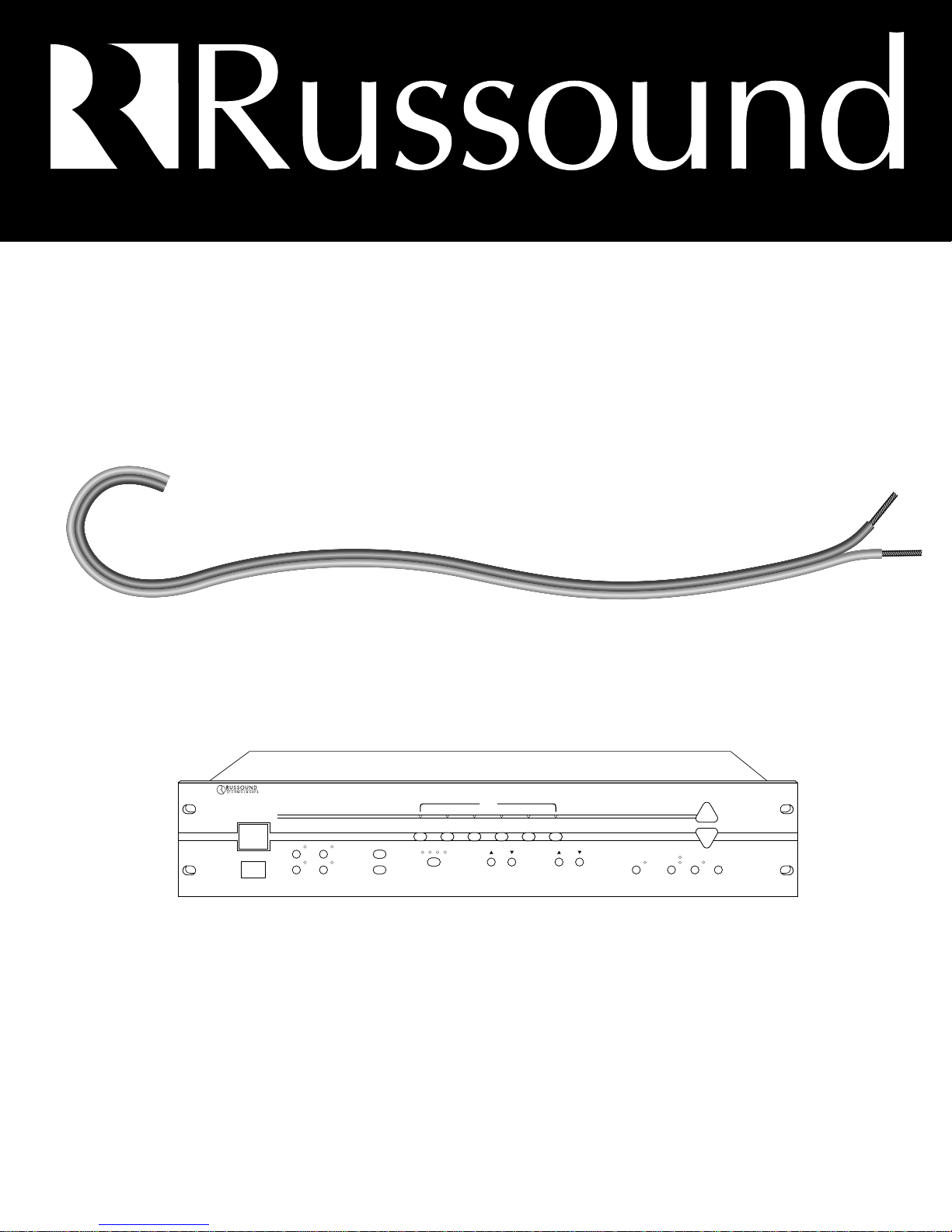
Figure 1 – A/V source connections
VCR (EXAMPLE OF SOURCE)
AUDIO/VIDEO SOURCES
Make line level and composite video connections from
source equipment to the CP 4.6 as shown in Figure 1.
Use high quality cables that are as short as possible to
keep signal integrity intact.
Wiring Instructions
Page 6
Wiring Instructions
5
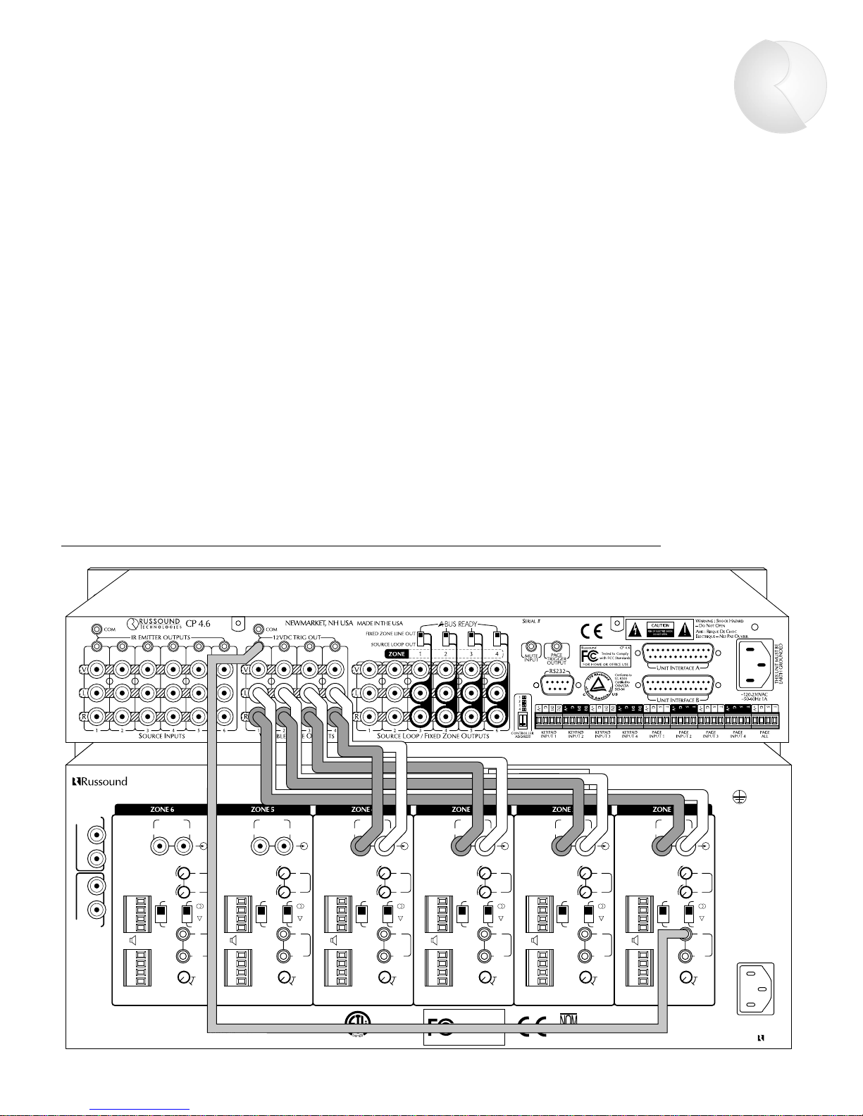
CONNECTING AMPLIFIERS
Connect the Zone Output of each CP 4.6 zone to one
line input of a multichannel amp. Figure 2 shows a
connection to the Russound DPA-6.12 Twelve Channel
Audio Amplifier. (Figure 2 also shows a trigger connection, discussed on p. 6.) If using multiple two-channel
amplifiers, such as the Russound DPA-1.2, connect as
shown in Figure 3 (see p. 6). Use good quality audio
cables that are as short as possible to keep signal
integrity intact.
MAIN BUS
INPUT
MAIN BUS
OUTPUT
BUS BUS BUS BUS BUS BUS
LINE LINE LINE LINE LINE LINE
STEREO STEREO STEREO STEREO STEREO STEREO
GAIN GAIN GAIN GAIN GAIN GAIN
BRGD
MONO
BRGD
MONO
BRGD
MONO
BRGD
MONO
BRGD
MONO
BRGD
MONO
DPA-6.12
NEWMARKET, NH USA
R
L
R
LLLLLL
LLLLLL
L
RRRRRR
RRRRRR
R
+
R
+
R
+
R
+
R
+
R
+
R
–
R
–
R
–
R
–
R
–
R
–
L
–
L
–
L
–
L
–
L
–
L
–
L
+
L
+
L
+
L
+
L
+
L
+
R
+
R
+
R
+
R
+
R
+
R
+
R
–
R
–
R
–
R
–
R
–
R
–
L
–
L
–
L
–
L
–
L
–
L
–
L
+
L
+
L
+
L
+
L
+
L
+
LINE INPUT LINE INPUT LINE INPUT LINE INPUT LINE INPUT LINE INPUT
+12V
TRIGGER
+12V
TRIGGER
+12V
TRIGGER
+12V
TRIGGER
+12V
TRIGGER
+12V
TRIGGER
IN IN IN IN IN
IN
111111
222222
333333
44444
4
∞∞∞∞∞∞
S
PEAKERS ASPEAKERS ASPEAKERS ASPEAKERS ASPEAKERS ASPEAKERS A
S
PEAKERS BSPEAKERS BSPEAKERS BSPEAKERS BSPEAKERS BSPEAKERS B
MUTING
DELAY TIME
MUTING
DELAY TIME
MUTING
DELAY TIME
MUTING
DELAY TIME
MUTING
DELAY TIME
MUTING
DELAY TIME
MINIMUM LOAD IMPEDANCE:
8 OHM PER CHANNEL WHEN BOTH SPEAKER A AND B OUTPUTS ARE USED
4 OHM PER CHANNEL WHEN SPEAKER ONLY A OR B OUTPUT IS USED
* FOR BRIDGED OPERATION SEE MANUAL
~120VAC
~60Hz
12A
THIS UNIT MUST BE
EARTH GROUNDED
DESIGNED IN THE USA
MADE IN TAIWAN
WARNING : SHOCK HAZARD –
D
O NOT OPEN
AVIS : RISQUE DE CHOC
ELECTRIQUE – NES PAS OUVRIR.
SERIAL #
Russound
FOR HOME OR OFFICE USE
DPA-6.12
Tested to Comply
with FCC Standards
Conforms to
UL 6500
Certified to
CSA C22.2 No1-94
68835
019
OUT OUT OUT OUT OUT OUT
100mA 100mA 100mA 100mA 100mA 100mA
******
Figure 2 – Multichannel amplifier connections, with tirgger connection shown to one channel
Page 7
6
Wiring Instructions
LINE INPUT
SENSING
SPEAKER A OUT
12V
TRIG
INPUT
12V TRIG
OUT 100mA
STEREO
VIDEO
INPUT
SENSING
DELAY
BRGD *
MONO
GAIN
SPEAKER B OUT
LR
1
234
5
AC
120V
60Hz
2A~
AMPLIFIED INPUT
SENSING
DEFAULT
AMPLIFIED INPUT
AVIS : RISQUE DE CHOC
ELECTRIQUE – NES PAS
OUVRIR.
* FOR BRIDGED OPERATION
SEE MANUAL
L
R
WARNING : SHOCK
HAZARD – DO NOT OPEN
Figure 3 – Two-channel amplifier connections
Figure 4 – Common and Zone trigger outputs
COMMON AND ZONE TRIGGER OUTPUTS
The CP 4.6 provides four Zone-Specific and one Common
+12VDC trigger outputs (Figure 4). The Zone-Specific
triggers are turned on when the corresponding zone is
on. The Common trigger is turned on when any zone is
on. All trigger outputs are turned on during a page.
Figure 2 (p. 5) shows a Zone trigger connection to the
Russound DPA-6.12 amplifier.
Page 8
7
Wiring Instructions
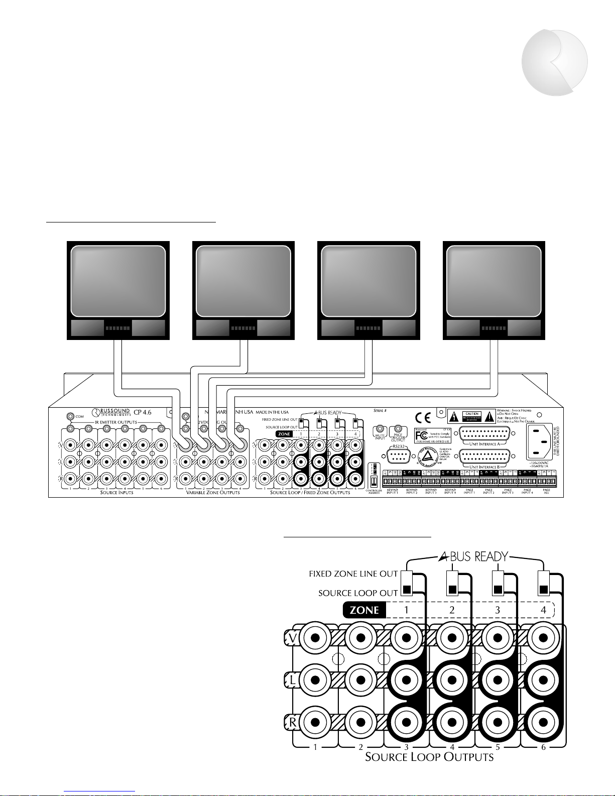
CONNECTING VIDEO MONITORS
Each CP 4.6 zone has a composite video output to allow viewing video from any of six A/V sources. Connect monitors
as shown in Figure 5 using RG6U cable with RCA type connectors. If more than two monitors are being used in a
zone, a composite video distribution amplifier is recommended. The CP 4.6 video outputs are buffered and are good
for up to 100’ of RG6U.
Figure 5 – Video Output connections
Figure 6 – Source Loop outputs
SOURCE LOOP OUTPUTS
The CP 4.6 has six buffered, fixed-level
audio/video outputs (Figure 6). When set to
SOURCE LOOP OUT, these output signals from
the corresponding input source. This source loop
configuration allows the CP 4.6 to pass source
signals to another component, such as a home
theater controller, or to another CP 4.6 for sharing sources in a multiple controller system.
Page 9
Wiring Instructions
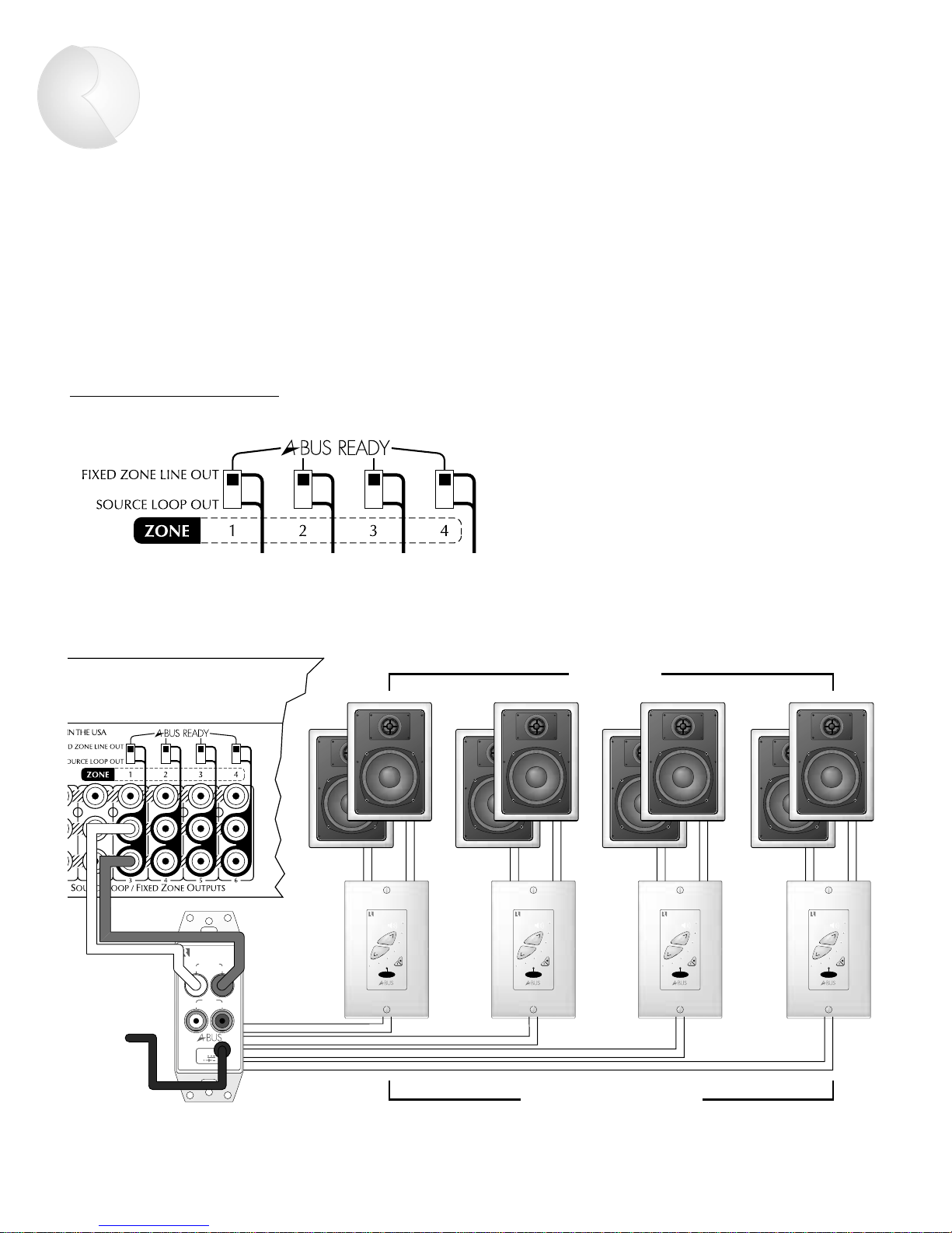
FIXED ZONE LINE OUT: CREATING SUBZONES
The CP 4.6 has six buffered, fixed-level audio/video outputs as shown previously in Figure 1 (p. 4). When set to
FIXED ZONE LINE OUT (Figure 7), the last four outputs can be used to create subzones of each main zone.
A subzone gets the same source selected for the main zone, and therefore needs only on/off and volume control.
The lower portion of Figure 7 shows four amplified Russound A-KP keypads added to Zone 1. All subzones get the
same Zone 1 source, but will have independent on/off and volume control via the A-KP keypad.
Figure 7 – Creating subzones
AUDIO IN
LR
AUDIO
OUT
POWER
+24V
4A
SIGNAL INTERFACE
LR
CP 4.6 REAR
CP 4.6 REAR
A-CB4 SIGNAL CONNECTING BLOCK
A-KP AMPLIFIED KEYPADS
SPEAKERS
8
Page 10
9
Wiring Instructions
Figure 8 – Paging trigger output
and mute input
PAGING TRIGGER OUTPUT
The CP 4.6 is equipped with a paging trigger output
(Figure 8) that switches on during a page. This output
can be used to trigger an external amplifier, muting
device, or other peripheral associated with paging.
(Paging peripherals are discussed on page 14.)
MUTE INPUT
The CP 4.6 system mutes when a +12VDC signal is
applied to the mute input (Figure 8). This allows
connection of external paging or muting devices.
Page 11
10
Control Functions
POWER – Controls power to entire system.
IR Receiver – Provides IR control for Zone 1.
ZONE SELECT – Selects current zone (1-4).
ZONE SELECT Indicators – Shows current zone.
ALL ON & ALL OFF – Turns all zones on or off. ALL ON can be preset
to selectively omit zone(s).
ON/OFF – On/off control for current zone.
ON/OFF Indicators – On/off status of current zone.
Source Select – Changes source for current zone.
Source Indicators – Shows selected source for current zone.
BASS & TREBLE Controls – Adjusts BASS and TREBLE (▲/▼) for
current zone. Bass & treble: 12 steps each, 2dB per step (-12dB to +12dB).
LOUDNESS – Selects LOUDNESS on/off for current zone. Loudness
selectively boosts bass & treble output at low volumes.
PARTY – Selects from 2 PARTY modes (SOURCE LINK or SOURCE/VOL LINK).
PARTY Indicators – Shows PARTY mode used.
MEMORY – Initiates MEMORY mode for current zone.
PRESET – Recalls stored settings for current zone.
VOLUME – Controls VOLUME for current zone. Volume: 40 steps,
2dB per step (-80dB to 0dB).
1
12
ON/OFF
ZONE SELECT
POWER
ALL
ON
ALL
OFF
BASS TREBLE
LOUDNESS PARTY
SOURCE / VOL LINK
SOURCE LINK
MEMORY
VOLUME
PRESET
34
23456
4 ZONE — 6 SOURCE AUDIO/VIDEO PREAMPLIFIER
CP 4.6
12
34
SOURCE
Figure 9 – CP 4.6 control functions
1
4
7
10
13
2
5
8
11
14
3
6
9
12
15
16
Page 12

Control Functions
11
MEMORY PROCEDURE
MEMORY allows for permanent storage of zone settings.
Source, volume level, bass level, treble level, loudness,
paging volume, and "ALL ON disable" settings can be
stored. Once stored, these settings can be accessed by
pressing PRESET.
To set MEMORY for a single zone:
1. Select a zone using the ZONE SELECT.
2. Adjust zone as desired.
3. Press MEMORY. The MEMORY indicator will light.
4. To store VOLUME, BASS, and TREBLE levels, press
the ▲ (up) button for the corresponding function.
5. To store current input source, press an
y source button.
6. To store loudness setting, press LOUDNESS.
7. To prevent the zone from turning on when All On
is activated, press ALL ON.
8. To preset paging volume, press VOLUME ▼ (down)
9. To exit, press MEMORY again. The MEMORY
indicator should no longer be illuminated.
To clear MEMORY for a sing
le zone:
1. Select a zone using ZONE SELECT.
2. Press MEMORY followed by PRESET.
3. Press MEMORY again to exit.
To clear MEMORY for all
zones:
1. Press MEMORY followed by ALL OFF.
PRESET PROCEDURE
PRESET recalls settings for the current zone previously
stored in memory. A preset can be recalled at the
CP 4.6 front panel, on a PCK keypad, or via the PRC-1
remote control.
1. Select a zone using ZONE SELECT.
2. Press PRESET.
Pressing PRESET on a PCK keypad or PRC-1 remote
control will recall the settings for that local zone.
PARTY MODE
Two PARTY modes allow synchronous operation of all
zones.
Source Link mode. Activated upon pressing PARTY
once. Source settings are linked for all zones. Any
changes to source selection at the CP 4.6 front panel
will be made simultaneously in all zones. However, zone
volumes can be adjusted independently.
Source Link mode procedure:
1. Set Zone 1 volume and source as desired for the
entire system. Turn on each zone you want to include
for PARTY mode.
2. Press PARTY once
. The SOURCE LINK indicator will
light and the settings made for Zone 1 will be reflected
in all other zones currently turned on.
Source/Volume Link mode. Activated upon pressing
PARTY twice. Source and volume settings are linked for
all zones. Any changes to source selection or volume in
one zone will be made simultaneously in all others.
Source/Volume Link mode procedure:
1. Repeat Step 1 above.
2. Press PARTY twice
. The SOURCE/VOL LINK indicator
will light and the settings made for Zone 1 will be
reflected in all other zones currently turned on.
Refer to Figure 9 at left for the following procedures.
Page 13
12
Peripheral Devices
D2
D1
GND
V+
4 CONDUCTOR
2 TWISTED PAIR WIRE
WITH SHEILD
1 PAIR TWISTED WIRE
WITH SHIELD
GND
OUT
N / C
+12V
MODEL #848
J-BOX RECEIVER
Figure 11 – IR device wiring
IR RECEIVER
CP 4.6 BACK
CP 4.6 BACK
PCK KEYPAD
Figure 10 – PCK wiring
PCK KEYPADS
Each of the CP 4.6’s zones can be remotely operated by
a keypad or IR device. There are four keypad ports on
the rear panel. Each port accommodates as many as
four Russound PCK keypads (4 per zone). Wire the PCK
keypads to the CP 4.6 keypad input as shown below in
Figure 10 using 22-24 AWG shielded 2 twisted pair wire.
IR DEVICES
The keypad ports are also compatible with infrared
devices such as Russound 848, 1257, 1258, and 844
IR receivers.
Wire IR devices as shown in Figure 11 using 22-24 AWG
1 pair twisted wire with shield.
Page 14
Peripheral Devices
13
Figure 12 – PCK zone control functions
PCK KEYPAD CONTROL FUNCTIONS
Infrared Receiver – Receives IR commands from
Russound PRC-1 remote or a source component’s
remote.
SYSTEM ON – Turns all zones on.
SYSTEM OFF – Turns all zones off.
ZONE ON/OFF – Turns zone on/off.
PRESET – Recalls stored zone settings.
TREBLE VOLUMEBASS
PR-4Z SYSTEM CONTROLLER
SELECT
CD TAPETUNER
VID2 DVDVID1
ZONE
ON/OFF
PRESETLOUD
SYSTEM
OFF
SYSTEM
ON
1
4
7
10
2
5
8
3
6
9
6
2 3
5 4
7
9
10
8
1
LOUD – Selects and indicates loudness on/off.
Source Select – Selects and shows input source.
SELECT – Selects function (bass, treble,
volume) to be adjusted with ▼/▲ buttons.
BASS / TREBLE / VOLUME Indicators –
Shows function selected for adjustment.
▼/▲ Buttons – Adjusts bass, treble, and
volume.
Page 15
14
Peripheral Devices
PAGING
The CP 4.6 has five paging inputs. The four ZoneSpecific PAGE INPUTS allow for paging to all zones
except the zone where the page originates. The PAGE
ALL input will allow paging to all zones. A page turns on
all zones to their respective preset paging volume (see
Memory Procedure, p. 11). All devices triggered by any
of the trigger outputs will also be turned on. Russound
offers many paging options to suit most applications.
See the Tech and FAQ sections at www
.russound.com
or call Russound for additional information.
SPG PAGING MODULE
The Russound SPG provides "push-to-talk" operation.
Use 22-24 AWG twisted pair shielded wire to connect
the SPG to the CP 4.6 page input as shown in Figure 13.
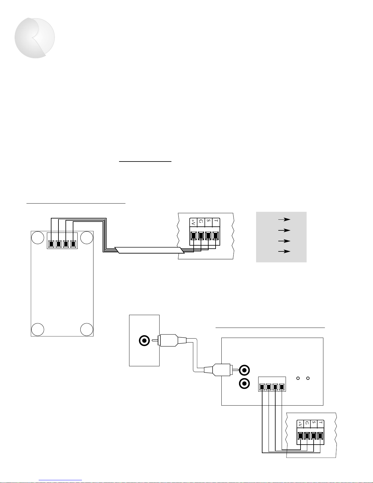
PTM-1 PAGING MODULE
The Russound PTM-1 is a signal-sensing paging adapter
for the CP 4.6 that accepts the page output or other
line-level audio output from telephone paging systems,
paging preamplifiers, switch-triggered voice/sound
recording devices, etc. Use 22-24 AWG twisted pair
shielded wire to connect the PTM-1 to the CP 4.6 page
input as shown in Figure 14.
CP 4.6 PAGE INPUT
4 CONDUCTOR TWISTED
PAIR SHEILD
TGR
GND
SIG
12+
Figure 13 – SPG wiring instructions
SPG PAGING MODULE
CP 4.6 PAGE INPUT
TSGV
PTM-1 PAGE TRIGGER MODULE
ON TGR
IN
OUT
OUT
PAGE
TGR T
GND G
SIG S
12+ +V
Figure 14 – PTM-1 wiring configuration
Page 16

Peripheral Devices
15
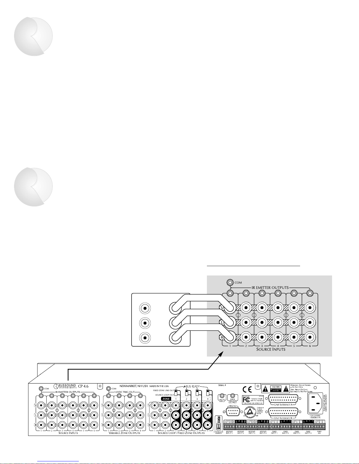
IR EMITTERS
The CP 4.6 has seven IR outputs: Source
1–6 and Common. Source 1–6 outputs
are source-specific and provide IR signals
only to the selected source; the Common
output provides IR signals to all
sources.
Source-specific IR outputs (Figure 15) are
useful when a system has two or more of
the same model source component,
allowing you to target the IR commands
to each individual component.
To connect multiple emitters to the
Common IR output, use the Russound
847 connecting block and a 1/8-inch,
2-conductor (mono) phone plug as
shown in Figure 16. Wire the tip of the
phone plug to the signal terminal of the
847 and the sleeve to the ground terminal of the 847.
Figure 16 – Common infrared output
RUSSOUND #845.1 MICRO EMITTERS
TO IR CONTROLLED EQUIPMENT
RUSSOUND #847
CONNECTING BLOCK
TIP
SLEEVE
1/8" (MONO)
PHONE PLUG
STRIPE WIRE
IS SIGNAL
(WIRES TO TIP)
845.1 MICRO EMITTERS TO
IR RECEIVER WINDOW
OF SOURCE EQUIPMENT
SOURCE 2
SOURCE 1
Figure 15 – Source-specific infrared outputs
Page 17

16
Peripheral Devices
PRC -1 REMOTE CONTROL
The Russound PRC-1 remote control is preprogrammed to
operate more than 1,000 audio and video components,
including the CP 4.6. Set it up by simply punching in a
three-digit code that matches your equipment. The PRC-1
also has the ability to learn new functions, allowing you to
customize it and update it as you add new equipment. The
PRC-1 operates up to eight different audio and video components in a home entertainment system.
The PRC-1 controls only the local zone you are in.
USING THE PRC -1 WITH THE CP 4.6
To activate the PRC-1 for use with the CP 4.6:
1. Turn on the CP 4.6 using its fr
ont-panel switch.
2. On the PRC-1, press the AUX and MUTE buttons
simultaneously, then release.
3. Point the PRC-1 toward the CP 4.6 and press the
three-digit code 0-8-1.
4. On the PRC-1, press the AUX button again to store
the code.
5. Henceforth, pressing the AUX button on the PRC-1
accesses all the preprogrammed codes for the CP 4.6.
All the functions available on the PCK keypad are also
available on the PRC-1. NOTE: The PRC-1 can turn on the
local zone by pressing the POWER button, and turn off
that zone by pressing the MUTE button.
TUNER CD TAPE
VID 1 VID 2 DVD
ALL ON
SYSTEM
ON
SYSTEM
OFF
ALL OFF PRESET
SHIFT
SLEEP
PRO.L
3.CH
TEST
BASS TREBLE
TUNER
TAPE CENTER
REAR CENTER DELAY
SURR
Ld
PIP
PRC-1
PROGRAMMABLE REMOTE CONTROL
CBLVCRTVSAT
AUXDVDCDAUD
POWER
MUTE
GUIDE
PAUS E
SEL
R
E
W
F
•
F
PLAY
STOP
MENU
EXIT
123
456
789
FAV
INFO
NEXT
+10
M1 M2 M3 M4
0ENTERALT
PRE.
CH
T/V
VOL CH
LIGHT
Figure 17 – PRC-1 Preprogrammed
& Learning Remote Control
Page 18

Multiple Controllers
17
DB-25 MALE / MALE CONNECTOR
Figure 18 – Interface cable connections for multiple CP 4.6s
INSTALLING MULTIPLE CP 4.6 CONTROLLERS
As many as four CP 4.6s can be cascaded via DB-25
connectors. Cascading links multizone functions such as
ALL ON, ALL OFF, PAGING, and PARTY mode so that
these functions can be used system-wide. (In order to
share sour
ces among linked CP 4.6s you must connect
the Source Loop outputs of the parent controller to the
A/V inputs of controller #2, and so on.)
Your CP 4.6 may either have 2 female DB-25s or
1 male and 1 female DB-25. For units equipped with
2 female DB-25s, you will need male-to-male cables as
shown in Figure 18. For units equipped with male and
female DB-25s, you will need a combination of male-tomale and female-to-female cables.
Page 19

18
Using the RS-232 Communications Port
CONTROLLER ADDRESS SWITCH SETTINGS
Up to 16 zones can be controlled from a single RS-232 port by
setting the Controller Address Switch located left of the DB-9
connector (Figure 19).
Controller #1 (Zones 1-4)
Controller #2 (Zones 5-8)
Controller #3 (Zones 9-12)
Controller #4 (Zones 13-16)
RS-232 COMMAND PROTOCOLS
Commands are sent from RS-232 controlling device to the CP 4.6 as 8 ASCII bytes. The first two ASCII bytes “RU”
establish that the command is a Russound command for zone commands only. The next 3 bytes “Z01” establish the
zone to be controlled. The last 3 bytes “ZON” comprise the command sent to that zone. Commands are sent as
ASCII values, asynchronous, 4800 bps, 8 data bits, 1 start bit, 1 stop bit, no parity.
CP 4.6 FEEDBACK BYTES TO CONTROLLING DEVICE
Feedback bytes will be sent immediately after a command is given to the CP 4.6. The first decimal byte “101”
(Zone 1) establishes which zone the update is for. The second decimal byte “40” (min. volume has been set) is the
update data. Each update starts with the zone number update value (101 - 116) and is followed by a control update
value (see list on next page). Commands are sent as decimal values, asynchronous, 4800 bps, 8 data bits, 1 start
bit, 1 stop bit, no parity.
The CP 4.6 is equipped with one DB-9 connector for RS-232 communication with Panja, Crestron, and similar
automation systems. All CP 4.6 control functions (except for paging) can be accessed through the RS-232 port. The
CP 4.6 will also send confirmation data to the controlling system. These updates will be performed when any change
has been executed or when the “SEND ZONE STATUS INFORMATION” request is sent to the CP 4.6.
Figure 19. Controller Address Switch
Page 20

19
RS-232 Commands & Update Values
UPDATE VALUES
0 thru 40 update volume position 40 (min) <-> 0 (min)
41 source 1 selected
42 source 2 selected
43 source 3 selected
44 source 4 selected
45 source 5 selected
46 source 6 selected
50 thru 62 update treble position 0 (min) <-> 12 (max)
70 thru 82 update bass position 0 (min) <-> 12 (max)
90 zone is on
91 zone is off
92 loudness contour is on
93 loudness contour is off
94 source lock party mode selected
95 source link party mode selected
96 party mode is off
ALL OTHER UPDATE VALUES (0 <-> 255) OTHER THAN
SHOWN ABOVE ARE RESERVED FOR FUTURE USE.
ZONE NUMBER UPD
ATE VALUES
101 update to be sent for zone 1
102 update to be sent for zone 2
103 update to be sent for zone 3
104 update to be sent for zone 4
105 update to be sent for zone 5
106 update to be sent for zone 6
107 update to be sent for zone 7
108 update to be sent for zone 8
109 update to be sent for zone 9
110 update to be sent for zone 10
111 update to be sent for zone 11
112 update to be sent for zone 12
113 update to be sent for zone 13
114 update to be sent for zone 14
115 update to be sent for zone 15
116 update to be sent for zone 16
200 update to be sent to all zones
RUZXXVLP volume level set followed by decimal value 40 (min) <-> 0 (max)
RUZXXBSP bass level set followed by decimal value 0 (min) <-> 12 (max)
RUZXXTBP trebel level set followed by decimal value 0 (min) <-> 12 (max)
RUZXXSRD send zone status information
ZONE C
OMMANDS
Zone number (XX) can be between 01 and 16. Use the addressing switch
(Figure 19) to set zone numbers (01-04), (05-08), (09-12), (13-16)
RUZXXZON zone on
RUZXXZOF zone off
RUZXXVLU volume up
RUZXXVLD volume down
RUZXXBSU bass up
RUZXXBSD bass down
RUZXXTBU treble up
RUZXXTBD treble down
RUZXXSR1 source input 1
RUZXXSR2 source input 2
RUZXXSR3 source input 3
RUZXXSR4 source input 4
RUZXXSR5 source input 5
RUZXXSR6 source input 6
RUZXXPST preset
RUZXXBSF bass level flat
RUZXXTBF treble level flat
RUZXXLOD loudness toggle on/off
MUL
TI-ZONE COMMANDS
RUALZOZN all zones on
RUALZOZF all zones off
RUSORCLC party mode (source link)
RUSORCLN party mode (source/volume link)
Page 21

20
Technical Specifications
Frequency Response: 20 - 20kHz + 0.1 dB max.
Total Harmonic Distortion: 0.06% max.
Signal-to-Noise Ratio: 95 dB min, "A" weighted
Maximum input voltage: 4.6 VRMS, 6 Volts peak
Maximum output voltage: 8.5 VRMS, 12 Volts peak
Volume Control: 0 dB to -80 dB (40 steps)
Bass and Treble Controls: +/- 12 dB (12 steps)
Standard Features: 6 Audio / Video source inputs
4 stereo audio/video outputs
4 keypad / Infrared ports
4 Paging unit ports
5 +12V Trigger outputs (4 zone specific, 1 common)
5 Infrared transport outputs (6 source specific, 1 common)
Built-in IR receiver for zone #1
RS-232 Interface for control of up to 4 CP4.6s from an external control system
Expansion ports allow cascading of up to four CP 4.6s (16 zones)
Optional Features: Full function PCK keypad
Full function PCK-IR keypad w/ built-in IR receiver
DSC direct source control IR learning keypad
DAN direct access numeric IR learning keypad
In-wall SPG paging module
PTM-1 telephone paging interface module
PRC-1 programmable remote control
Power requirements: AC 110 – 240 volts, 50 - 60Hz, 1 AMP.
Dimensions: 19" W x 12" D x 3.6" H.
Weight: 12 lbs.
The CP 4.6 complies with the requirements of the standards for Audio Video Products and Accessories (UL 1492, 1st
Edition) and Radio, Television, and Electronic Apparatus (CSA C22.2 No. 1-M94).
Page 22

21
Warranty & Repair
The Russound CP 4.6 is fully guaranteed against all defects in materials and workmanship for two (2) years from the date of purchase. During this period, Russound will
replace any defective parts and correct any defect in workmanship without charge for
either parts or labor. For this warranty to apply, the unit must be installed and used
according to its written instructions. If service is necessary, it must be performed by
Russound. The unit must be returned to Russound at the owner’s expense and with
prior written permission. Accidental damage and shipping damage are not considered
defects under the terms of the warranty. Russound assumes no responsibility for defects
resulting from abuse or servicing performed by an agency or person not specifically
authorized in writing by Russound. Damage to or destruction of components due to
improper use voids the warranty. In these cases, the repair will be made at the owner’s
expense. To return for repairs, the unit must be shipped to Russound at the owner’s
expense, along with a note explaining the nature of the service required. Be sure to pack
the unit in a corrugated container with at least 3 inches of resilient material to protect
the unit from damage in transit.
Before returning a unit for repair, call Russound at (603) 659-5170 for a
Return Authorization number. Write this number on the shipping label and ship to:
Russound
5 Forbes Road
Newmarket, NH 03857
Attn: Service
Page 23

Russound Technologies
5 Forbes Road, Newmarket, NH 03857
tel 603.659.5170 • fax 603.659.5388
e-mail: tech@russound.com
www.russound.com
fax-on-demand: 603.659.5590 28-0097
Page 24

PR-4Zi and CP4.6 TEST PROCEDURE
The purpose of this Test Procedure is to instruct not only the Russound
Test Department on how to test the product but to instruct any outside
Service Technician that might need to do so as well. There are several
pictures throughout the Test Procedure to help the technician test the
product.
While proceeding through the procedure there will be several steps that
have a bold “Test:
Test Department” on how to accomplish these connections using the
equipment provided the Test Department.
”. These are special instructions for the “Russound
Page 25

Equipment Needed: Line Level Audio Source (Tuner)
CP4.6
CP4.6 Diagnostic Program
Speakers
CP4.6 Instruction Manual
12Volt LED Indicator (1/8 inch jack, LED, 1K ohm resistor)
IR LED Indicator
2 845.1
Amplifier
PCK-IR
SPG
DPA 1.2
Power Cord (09-0504)
DB-25 Cable
RS-232 Cable
Inspection: Inspect Sheet Metal for scratches
Inspect screening for correct labeling.
Turn on unit with ON/OFF power switch
Start Up:
1. Test: Confirm the Speakers are either not connected to the DPA 1.2 or are in the
off position.
2. Connect the Power Cord (09-0504) to the back of the CP4.6 and the other end to
an AC outlet.
Turn on the unit by pressing the ON/OFF switch on the front top left of the unit.
Front Panel Test:
Note: All four zones should be off when the CP4.6 is first turned on. Refer to figures 1,2
and 3 for button assignment.
1. ON/OFF
– Turn on Zone 1 by pressing the ON/OFF button on the front panel
then turn it off. Turn Zone 1 back on. The ON/OFF light for that zone should
turn off and back on.
2. SOURCE LIGHTS
– Press each of the six source buttons. Each source light
should light as soon as the button is pressed and the previous light should go off.
3. LOUDNESS – Turn on and off loudness. The loudness light should turn on and
off on the front panel.
4. MEMORY/PRESET – Press MEM, Memory light (green) should light. Press
MEM again, Memory light should go off.
5. PARTY MODE – Press PARTY, Red Source Link light should light. Press
PARTY again, Green Source/Volume Link light should light. Red Source Link
light should go out. Press PARTY again, Green Source/Volume Link light should
go out. Neither light should be lit.
2
Page 26

6. ALL ON – With all zones off press ALL ON. All zone LEDs should go on.
7. ALL OFF
– With all zones on press ALL OFF. All zone LEDs should go off.
Figure 1.
Figure 2.
3
Page 27

Figure 3.
12Volt Trigger Out Test:
1. Turn on all zones by pressing "ALL ON" on the front of the CP4.6. All four zone
LEDs on front panel should illuminate. Check the Common 12Volt Trigger Out
on rear panel, there should be 12VDC. Check the 12Volt Trigger Outputs (4),
there should be 12VDC at each output. Test:
Check the Common 12Volt
Trigger Out on rear panel with the 12Volt LED Indicator. The LED should
illuminate. Check the 12Volt Trigger Outputs (4) on rear panel, again the LED
should illuminate.
2. Turn off all zones by pressing ALL OFF on the front of the CP4.6. All zone
LEDs on front panel should turn off. Check the Common 12Volt Trigger Out,
there should not be 12VDC. Check the 12Volt Trigger Outputs (4), there should
not be any voltage. Test:
Check the common 12Volt Trigger Out, with the
12Volt LED Indicator. The LED should not illuminate. Check the 12Volt
Trigger Outputs (4) on rear panel, none of the individual zone 12Volt Trigger
Outputs should illuminate.
Zone Test:
1. Connect a line level audio source to the Source 1 Left and Right Input, an
amplifier to the Variable Zone Output 1 on the CP4.6. Connect speakers to the
amplifiers output. Test: Attach the “Zone 2 ADP-1” line level output to the
Source 1 Left and Right Input on the CP4.6. Ensure the line level audio source
(Tuner) is turned on and producing a clear signal. Attach the amplified speakers
to the connector labeled speakers and ensure the speakers are set at halfway. The
speaker on the right should have the volume and on/off switch on the rear. Attach
the DPA 1.2 to the Variable Zone Output 1.
2. Attach a PCK-IR Keypad to the Keypad Input for Zone 1. Test: Attach the Test
PCK-IR Keypad to the Keypad Input for Zone 1.
4
Page 28

Figure 5.
Figure 6.
Figure 7.
5
Page 29

Note: Steps 3 through 10 should be done on the CP 4.6.
3. Turn Zone 1 on by pressing ON/OFF, the Zone 1 LED should illuminate.
4. Press VOLUME UP the volume should increase. The increase should be heard
through both speakers.
5. Press VOLUME DOWN the volume should decrease. The decrease should be
heard through both speakers.
6. Press BASS UP the bass should increase.
7. Press BASS DOWN the bass should decrease.
8. Press TREBLE UP the treble should increase.
9. Press TREBLE DOWN the treble should decrease.
10. Press LOUDNESS there should be an audible enhancement of both bass and
treble. The LOUDNESS LED should be illuminated. Press LOUDNESS again
the effect should go away and the LED should no longer be illuminated.
11. Apply 12VDC to the Mute Input on the back of the CP4.6. The “Line Level
Audio Source” should no longer be heard. Test: Connect an 846 Power Supply
to the Mute Input. The “Line Level Audio Source” should no longer be heard.
12. Disconnect the 12VDC from the Mute Input, the “Line Level Audio Source”
should return to its previous levels and be heard. Test:
Disconnect the 846
Power Supply from the Mute Input. The “Line Level Audio Source” should
return to its previous levels and be heard.
13. Change sources on the Keypad. Ensure the source-selected changes on the CP4.6.
14. Change sources on the CP4.6. Ensure the source-selected changes on the Keypad.
Memory/Preset Test:
1. Connect the line level audio source to Source 1 input. Test: Attach the “Zone 2
ADP-1” Line Level Output to the Source 1 Input on the CP4.6.
2. Attach the amplifier to the Variable Zone Output 1 on the CP4.6. Test: Attach the
DPA 1.2 to the to Variable Zone Output 1.
3. With the CP4.6 set for Zone 1 perform the following steps.
4. Set the Volume, Bass, Treble, and Loudness for comfortable settings.
5. Press the Memory button, the memory LED should light.
6. While the Memory indicator is lit press the following buttons: Source 1, Volume
, Bass up, Treble Up, and Loudness.
Up
7. Press the Memory button, the memory LED should no longer be lit.
8. Select Source 2, Volume all the way down, Bass all the way down, Treble all the
way down, Loudness off.
9. Press the Preset button on the front panel. Zone 1 should now reflect the same
settings as set in step (2.).
10. Press Memory then Preset and then Memory. This clears the Memory Preset.
Source Input Test:
1. The line level source should be attached to the Source 1 input. The 845.1 should
be connected to the Common IR Output. Test:
The “Zone 2 ADP-1” should be
attached to the Source 1 input. The 845.1 should be connected to the Common IR
6
Page 30

Output. Attach the IR LED Indicators to the all Source 1 Emitter Outputs. The
Test PCK-IR Keypad should still be attached to the Zone 1 Keypad input.
2. Control Source 1 component with the remote from the PCK-IR Keypad. Ensure
the source can be controlled from both the Common IR Output and the Source IR
Output. Test: Control the Tuner with the remote from the PCK-IR Keypad.
Ensure the IR LED Indicator that is attached to the Source 1 Emitter Output is
blinking when the remote is activated.
3. Disconnect the Right Side of the line level source output from the Source 1 input.
Listen to ensure the line level source is only being heard in one speaker. Test:
Disconnect the Right Side of the “Zone 2 ADP-1” output from the Source 1 input.
Listen to ensure the Audio is only being heard in one speaker.
4. Reconnect the Right Side of the line level source output to the Source 1 input.
Test: Reconnect the Right Side of the “Zone 2 ADP-1” output to the Source 1
input.
5. Disconnect the Left Side of the line level source output from the Source 1 input.
Listen to ensure the line level source is only being heard in one speaker. Test:
Disconnect the Left Side of the “Zone 2 ADP-1” output from the Source 1 input.
Listen to ensure the Audio is only being heard in one speaker.
6. Reconnect the Left Side of the line level source output to the Source 1 input.
Test: Reconnect the Left Side of the “Zone 2 ADP-1” output to the Source 1
input. Listen to ensure that the Audio is heard through both speakers.
7. Move the line level audio source to Source 2 and repeat steps (1. through 6.).
Repeat for all sources. Test:
Move the “Zone 2 ADP-1” to Source 2 and repeat
steps (1. through 6.). Repeat for all sources.
Perform the Zone Test, Memory/Preset Test and Source Input Test for Variable
Zone Outputs 2,3 and 4.
Source/Video Loop Output Test:
Note: There is only four “Fixed Zone Line Outputs” on the CP4.6, while there is six
“Source Loop Outputs”. The four “Fixed Zone Line Outputs” are labeled at the top in
gold coloring while the six “Source Loop Outputs” are labeled underneath of the RCA
jacks on the rear of the CP4.6.
1. Connect the line level audio source to Source 1 Input. Test:
Attach the “Zone 2
ADP-1” Line Level Output to the Source 1 Input on the CP4.6.
2. Attach the amplifier to the Source Loop Output 1 on the CP4.6. Test:
Attach the
DPA 1.2 to the to Source Loop Output 1.
3. Put the “A-Bus” Ready switches (4) on the rear of the CP4.6 in the “Source Loop
Out” position.
4. Ensure that Zone 1 on the front panel is selected to Source 1.
5. The audio from the line level audio source (Tuner) should be heard through both
speakers.
6. Disconnect the Right Side of the line level source output from the Source 1 input.
Listen to ensure the line level source is only being heard in one speaker. Test:
7
Page 31

Disconnect the Right Side of the “Zone 2 ADP-1” output from the Source 1 input.
Listen to ensure the Audio is only being heard in one speaker.
7. Reconnect the Right Side of the line level source output to the Source 1 input.
Reconnect the Right Side of the “Zone 2 ADP-1” output to the Source 1
Test:
input.
8. Disconnect the Left Side of the line level source output from the Source 1 input.
Listen to ensure the line level source is only being heard in one speaker. Test:
Disconnect the Left Side of the “Zone 2 ADP-1” output from the Source 1 input.
Listen to ensure the Audio is only being heard in one speaker.
9. Reconnect the Left Side of the line level source output to the Source 1 input.
Test: Reconnect the Left Side of the “Zone 2 ADP-1” output to the Source 1
input. Listen to ensure that the Audio is heard through both speakers.
10. Connect the Right Side of the line level audio source to the Source 1 Video Input.
Disconnect the Left Side of the line level audio source from the CP4.6. Attach
the Right Side of the amplifier to the Source Loop 1 Video Output. Disconnect
the Right Side of the amplifier from the CP4.6. Test:
Connect the Right Side of
the “Zone 2 ADP-1” to the Source 1 Video Input on the CP4.6. Disconnect the
Left Side of the “Zone 2 ADP-1 from the CP4.6. Attach the Right Side of the
DPA 1.2 to the Source Loop 1 Video Output. Disconnect the Left Side of the
DPA 1.2 from the CP4.6.
11. The music should be heard through the right speaker.
12. Perform steps (1. through 11.) for Source Inputs 2 through 6.
Figure 8.
Fixed/Video Zone Output Test:
Note: There are only four “Fixed Zone Line Outputs” on the CP4.6, while there are six
“Source Loop Outputs”. The four “Fixed Zone Line Outputs” are labeled at the top in
gold coloring while the six “Source Loop Outputs” are labeled at the bottom.
1. Connect the line level audio source to Source 1 input. Test:
ADP-1” Line Level Output to the Source 1 Input on the CP4.6.
2. Attach the amplifier to the Fixed Zone Line Out 1 on the CP4.6. Test:
DPA 1.2 to the to Fixed Zone Line Out 1.
Attach the “Zone 2
Attach the
8
Page 32

3. Put the “A-Bus” Ready switches (4) on the rear of the CP4.6 in the “Fixed Loop
Out” position.
4. Ensure that Zone 1 on the front panel is selected to Source 1.
5. Listen to ensure the audio is heard through both speakers.
6. Press the ALL OFF button. The audio should still be heard.
7. Select Source 2. The audio should no longer be heard.
8. Select Source 1. The audio should now be heard.
9. Disconnect the Right Side of the line level source output from the Source 1 input.
Listen to ensure the “Line Level Source” is only being heard in one speaker.
Disconnect the Right Side of the “Zone 2 ADP-1” output from the Source 1
Test:
input. Listen to ensure the Audio is only being heard in one speaker.
10. Reconnect the Right Side of the line level source output to the Source 1 input.
Test:
Reconnect the Right Side of the “Zone 2 ADP-1” output to the Source 1
input.
11. Disconnect the Left Side of the line level source output from the Source 1 input.
Listen to ensure the line level source is only being heard in one speaker. Test:
Disconnect the Left Side of the “Zone 2 ADP-1” output from the Source 1 input.
Listen to ensure the Audio is only being heard in one speaker.
12. Reconnect the Left Side of the line level source output to the Source 1 input.
Listen to ensure that the Audio is heard through both speakers. Test: Reconnect
the Left Side of the “Zone 2 ADP-1” output to the Source 1 input. Listen to
ensure that the Audio is heard through both speakers.
13. Connect the Right Side of the line level audio source to the Source 1 Video Input.
Disconnect the Left Side of the line level audio source from the Source 1 input.
Attach one side of the amplifier to the Fixed Zone Line 1 Video Output.
Disconnect the Left Side of the amplifier from the CP4.6. Test: Connect the
Right Side of the “Zone 2 ADP-1” to the Source 1 Video Input on the CP4.6.
Disconnect the Left Side of the “Zone 2 ADP-1” from the CP4.6. Attach the
Right Side of the DPA 1.2 to the Source Loop 1 Video Output. Disconnect the
Left Side of the DPA 1.2 from the CP4.6.
14. The music should be heard through the right speaker.
15. Perform steps (1. through 14.) for Fixed/Video Zone 2 through 4.
Infra-Red control (Zone 1 only):
1. Change sources for Zone 1, using the PRC-1 remote and pointing it at the IR
receiver on the front panel. This receiver is only for Zone 1
.
Party Mode:
1. Turn all zones on and connect a PCK-IR Keypad to the Zone 1 Keypad input.
2. Ensuring the CP4.6 is set for Zone 1 scroll through the sources on the Keypad and
watch the front panel on the CP4.6 and make sure the CP4.6 is changing sources.
3. Scroll through the sources on the front panel of the CP4.6 and ensure the sources
are changing on the PCK-IR.
4. Set Zones 2, 3, and 4 to Source 6 and volume all the way down.
9
Page 33

5. Set Zone 1 to Source 1.
6. Press The Party button once, the Source/Volume Link indicator will light.
7. Zones 2, 3, and 4 should now be on Source 1.
8. Set the CP4.6 for Zone 4 by selecting the Zone 4 button. Change the source to
Source 2. Set the CP4.6 back to Zone 1, the source should now be set for Source
2.
9. Press The Party button again, the Source/Volume Link indicator should light.
10. Attach the PCK-IR Keypad to Zone 2 on the CP4.6. Change the volume from the
PCK-IR Keypad. Change the source from the Keypad. Both the volume and
source should change from the Keypad.
11. Press The Party button again the Source/Volume Link indicator should no longer
be lit.
Page/Memory/Preset:
1. With the CP4.6 set for Zone 1 perform the following steps on the CP4.6.
2. Set the Volume for a comfortable setting.
3. Press the Memory button, the memory LED should light.
4. While the Memory indicator is lit press the following button Volume
Down.
5. Press the Memory button, the memory LED should no longer be lit.
6. The Preset Paging volume is now set.
Paging:
1. Ensure the Audio is being heard through Zone 1 on the CP4.6. Test: Ensure the
Tuner is being heard through the CP4.6.
2. Connect a SPG Paging module to the Zone 1 page input. Test: Attach the Test
SPG Paging module to the page input for Zone 1.
Figure 9.
3. Press the SPG module button and speak into the Keypad. You should not be able
to hear your voice over the speakers. The line level audio source (Tuner) will not
be heard when the button is pressed.
4. Connect a SPG Paging module to the Zone 2 page input. Test:
SPG Paging module to the page input for Zone 2.
5. Test: Connect the 12Volt LED Indicator to the Page Trigger Output.
Attach the Test
10
Page 34

6. Press the SPG Keypad button and speak into the Keypad. You should be able to
hear your voice over the speakers.
7. Check the Page Trigger Output on the back of the CP4.6. There should be
12VDC, every time a page is initiated. Test:
The LED on the 12Volt LED
Indicator should light every time a page is initiated.
8. Connect the SPG Keypad to Zone 3,4 and Page All. Repeat steps (6. through 7.).
9. The page should be heard through all Zones except the one where the page
originates.
Perform Page/Memory/Preset and Paging for Variable Zone Outputs 2,3 and 4.
Video Test:
1. Press the ALL ON button on the CP4.6. All four zone LEDs should light up.
2. Connect the Right Side of the line level source to the Source 1 Video Input. Test:
Connect the Right Side of the “Zone 2 ADP-1” to the Source 1 Video Input on the
CP4.6.
3. Take the cable connected to the Right Zone 1 Output and move it to the Zone 1
Video Output.
4. Select Source 1 on Zone 1 on the front panel.
5. The music should be heard through one of the speakers.
6. Move the Right Side of the line level source to the Source 2 Video Input. Test:
Connect the Right Side of the “Zone 2 ADP-1” to the Source 2 Video Input on the
CP4.6.
7. Select the Source 2 on Zone 1 on the front panel.
8. The music should be heard through one of the speakers.
9. Perform steps (2. through 8.) for Source Inputs 3 through 6.
10. Perform the Video Test steps (2. through 8.) for Zones 2, 3 and 4.
Memory Zone Lock Out:
1. Press the ALL OFF button.
2. Starting with the CP4.6 Zone 1 selected, press the Memory button. The memory
indicator will light.
3. Press the ALL ON button. None of the lights should turn on.
4. Press the Memory button.
5. Press the ALL OFF button.
6. Repeat steps (1. through 4.) for Zones 2, 3 and 4.
7. Press the ALL ON button. None of the lights should turn on.
8. Starting with Zone 1, press the Memory button. The memory indicator will light.
9. Press the PRESET button.
10. Press the MEMORY button.
11. Repeat steps (7. through 9.) for Zones 2, 3 and 4.
12. Press the ALL ON button. All four zone indicator lights should turn on.
11
Page 35

RS232 Test:
1. Connect the RS-232 port on the CP 4.6 to the RS-232 communications port on a
computer, using a standard DB-9 RS-232 cable.
2. Open the CP 4.6 Diagnostic Program by clicking the CP 4.6 Diagnostic Program
Icon on the computer.
3. On the Diagnostic Program dialog box, select the “COM Port” drop-down list to
the corresponding communications port being used on the connected computer
(COM1 or COM2).
4. On the Diagnostic Program dialog box, select the “Controller Address” dropdown list to Zones 1-
5. Select Zone 1 in the “Zone Number” selection area of the Diagnostic Program’s
dialog box.
6. Adjust the Controller Address Switches so that they are selected to Controller
Address 1 (both switches down).
7. Power on the CP 4.6.
8. Control Zone 1 on the CP4.6. The Diagnostic Program should reflect source
selection, volume and tone control changes.
9. Control Zone 1 source selection using the Diagnostic Program. The changes
should be reflected on the CP 4.6 front panel.
10. Power off the CP 4.6.
11. Adjust the Controller Address Switches so that they are selected to Controller
Address 4 (both switches up).
12. Power on the CP4.6
13. On the Diagnostic Program dialog box, select the “Controller Address” dropdown list to Zones 13-16.
14. Select Zone 13 in the “Zone Number” selection area of the Diagnostic Program’s
dialog box.
15. Control Zone 1 on the CP4.6. The Diagnostic Program should reflect source
selection, volume and tone control changes.
16. Control Zone 13 source selection using the Diagnostic Program. The changes
should be reflected on the CP 4.6 front panel.
17. Adjust the Controller Address Switches so that they are selected to Controller
Address 1 (both switches down) for shipping.
Unit-to-Unit Interaction:
1. Connect a second CP4.6 to the one being tested using the DB-25 cable attaching
at the Unit Interface connectors.
2. Turn on both CP4.6s.
3. Make sure all zones on both units are off.
4. Press the ALL/ON button on one of the CP4.6s. All zones on both CP4.6s should
turn on.
5. Press the ALL/OFF button on the other CP4.6s. All zones on both CP4.6s should
turn off. Press the ALL/ON button on one of the CP4.6s.
6. Press the Party Mode button. Both CP4.6s should show the Source Link indicator
lit.
12
Page 36

7. With one of the CP4.6s with Zone 1 selected, change sources on the front panel.
The source change should be seen on both CP4.6s.
8. Set the other CP4.6 for Zone 2, change sources on the front panel. The source
change should be seen on both CP4.6s.
9. Press the Party Mode button twice on one of the CP4.6s, both units should now
return to normal operation.
10. Press Memory then All Off to clear all presets.
Ground Test:
1. Ensure the Assembly Department attached the “Ground Symbol” sticker on the
inside of the rear panel, to the right of the “Ground Stud” near the AC receptacle.
See model for example.
2. Disconnect power and any accessories and/or additional CP4.6s that are
connected.
3. With the cover removed, test continuity from the ground terminal of the power
input connector to the following points.
a. Ground terminal of the 3-prong AC outlet.
b. Ground lug on the power supply.
c. Chassis main ground screw.
d. Chassis.
e. Power supply screw.
f. Ground plane on PCB.
Hi-Pot Test:
From TUV.
As for the Hi pot test requirement, the value is 1500VAC (2121VDC) between phase/
neutral and chassis (ground) for 1 sec. Also, a ground continuity test needs to be
performed between ground and chassis at 25A for 1 sec.
Cover:
1. Inspect cover for CP4.6.
2. Attach cover.
Labels:
1. Affix the manufacturers Serial # on the back of the CP4.6. Place the Revision
sticker and date sticker on the bottom of the CP4.6.
2. Perform the Test Departments assembly procedure.
THE TEST PROCEDURE IS COMPLETE.
Poe
Last Updated: 6/14/01
13
Page 37

CP4.6 Main PCB R2.sch-1 - Thu Apr 05 11:22:21 2001
Page 38

CP4.6 Main PCB R2.sch-2 - Mon Nov 17 15:07:04 2003
Page 39

CP4.6 Interface PCB R0.sch-1 - Tue Apr 10 10:10:17 2001
Page 40

1Page * Multi-Level Ex
p
losion By Parent Part Identifier *
Parent Part Identifier Range: 1100-118814 - 1100-118814, Effective: 7/26/2002
LTOUMQC BTLLC
A
lternate Par
t
PTRe
v
ECN #SCREffectivit
y
Quantit
y
Part Identifier Description
Drawing #Commodit
y
PR-4ZI 1100-118814
A
4 ZONE 6 SRCE A/V PREAMP MSMZS-PR
MS PH FL 4-40 X 1/4 BLK 07-0010 1 2.0000006/26/2002 U EA 0 N 0 D0
HARDWARE
SM PH PN 6 X 1/4 T-A BLK 07-0101 1 8.0000006/26/2002 U EA 0 N 0
Y
0
HARDWARE
SM PH PN 6 X .300 BLK 07-0108 1 8.0000006/26/2002 U EA 0 N 0 B
SCREWS FROM GLD FT. KPBO HARDWARE
CONN 3.5MM 4P PCK HTSTMP 08-0131 1 4.0000006/26/2002 U EA 0 N 0 B
RIA # 31169104US0002 CONNECTOR
CONN 3.5MM 4P SPG HTSMTP 08-0132 1 5.0000006/26/2002 U EA 0 N 0 B
RIA # 31169104US0001 CONNECTOR
POWER CORD 16AWG/3COND 09-0504 1 1.0000006/26/2002 U EA 0 N 0 B0
PDI PART # 10087 PWR CORD
IC PIC 16C65B-04/P PROM 18-0402 1 1.0000007/12/2002 U EA 0 N 0 B0
MICRO-CHIP SEMICOND
IC PIC 16C57XT/P PROM 18-0403 1 1.0000006/26/2002 U EA 0 N 0 B0
MICRO-CHIP SEMICOND
IC PIC17C756-08/L 18-0414 1 1.0000006/26/2002 U EA 0 N 0 B
MICROCHIP SEMICOND
LABEL DATE CODE STICKER 26-0505 1 1.0000006/26/2002 U EA 0 N 0 B0
LABELS
LABEL SERIAL NUMBER 26-0506 1 1.0000006/26/2002 U EA 0 N 0 B0
LABELS
CARTON PR-4ZI 27-0024 1 1.0000006/26/2002 U EA 0 N 0 B0
PACKING
END PCS PR-4ZI 27-1017 1 2.0000006/26/2002 U EA 0 N 0 B0
SINGLE PIECE PACK-FOAM
BAG
,
PLASTIC 24" X 30" 27-1508 1 1.0000006/26/2002 U EA 0 N 0 D
500 BAGS/CASE PACK-BAG
BAG
,
PLASTIC 8" X 10" 27-1512 1 1.0000006/26/2002 U EA 0 N 0 D
PACK-BAG
MANUAL PR-4ZI 28-0107 1 1.0000007/9/2002 U EA 0 N 0 B
MANUAL
PR-4ZI & CP4.6 COVER 30-0656 1 1.0000006/26/2002 U EA 0 N 0 B0
COVER
PR-4ZI PREAMP ASSY 41-8001 1 1.0000007/1/2002 U EA 0 N 0 S
READY FOR TEST ASSY-PRAMP
RES 1/4W 5% 560 OHM 02-0002 .2 4.0000007/1/2002 U EA 0 N 0
Y
0
RESISTOR
RES 1/4W 5% 330 OHM 02-0010 .2 12.0000007/1/2002 U EA 0 N 0
Y
0
XICON 291-330/1000 RESISTOR
RES 1/4W 5% 1 K 02-0014 .2 4.0000007/1/2002 U EA 0 N 0
Y
0
XICON 291-1K RESISTOR
ELEC RD 1.0 UF 50V 03-0008 .2 4.0000007/1/2002 U EA 0 N 0
Y
0
XICON 140-XRL50V1.0 CAPACITOR
CERA. MINI .1UF 50V EPOXY03-0411 .2 1.0000007/1/2002 U EA 0 N 0
Y
0
XICON 21RZ310 CAPACITOR
7/26/2002 2:22:38 PMBill of Materials - Explosion/Implosion Reports, BOMRPT.RPT PENGELRUSSOUND
Page 41

2Page * Multi-Level Ex
p
losion By Parent Part Identifier *
Parent Part Identifier Range: 1100-118814 - 1100-118814, Effective: 7/26/2002
LTOUMQC BTLLC
A
lternate Par
t
PTRe
v
ECN #SCREffectivit
y
Quantit
y
Part Identifier Description
Drawing #Commodit
y
SW ARCOLECTRIC W/GLD SCRN04-0212 .2 1.0000007/1/2002 U EA 0 N 0 B0
H8650VBBB W/GOLD SCRN SWITCH
SW BUTTON ARROW
(
BLACK) 05-0006C .2 2.0000007/1/2002 U EA 0 N 0
Y
0
BUTTON
SW BUTTON ROUND
(
BLACK) 05-0007C .2 12.0000007/1/2002 U EA 0 N 0
Y
0
BUTTON
SW BUTTON OVAL
(
BLACK) 05-0009C .2 9.0000007/1/2002 U EA 0 N 0
Y
0
BUTTON
MS PH PN 6-32 X 1/4 BLK 07-0001 .2 2.0000007/1/2002 U EA 0 N 0
Y
0
HARDWARE
MS PH PN 6-32 X 1/4 W/LW 07-0021 .2 17.0000007/1/2002 U EA 0 N 0
Y
0
W/ EXTERNAL TOOTH LCKWSHR HARDWARE
SM PH PN 6 X 1/4 T-A BLK 07-0101 .2 8.0000007/1/2002 U EA 0 N 0
Y
0
HARDWARE
SM PH FLT 6 X 1/2 T-A BLK07-0107 .2 2.0000007/1/2002 U EA 0 N 0
Y
MCMASTER # 90033A150 HARDWARE
SM PH PN 6 X .300 BLK 07-0108 .2 2.0000007/1/2002 U EA 0 N 0 B
SCREWS FROM GLD FT. KPBO HARDWARE
NUT
,
HEX 6-32 X 1/4 STL 07-0300 .2 6.0000007/1/2002 U EA 0 N 0
Y
0
HARDWARE
LCK WSH INT THT #6 STL 07-0400 .2 7.0000007/1/2002 U EA 0 N 0
Y
0
HARDWARE
LUG
,
CLOSE LOOP #6 07-0410 .2 2.0000007/1/2002 U EA 0 N 0
Y
0
HARDWARE
SPLIT LCK WSH #6 07-0417 .2 4.0000007/1/2002 U EA 0 N 0
Y
MCMASTER P/N 92146A007 HARDWARE
SPCER PHNL N-6 5/16 X 1/407-0518 .2 6.0000007/1/2002 U EA 0 N 0
Y
RAF # 1125-6-PH HARDWARE
LED STAND OFFS .150 07-2004 .2 18.0000007/1/2002 U EA 0 N 0
Y
0
BIVAR ELM 5-150 HARDWARE
BLACK WIRE TIE 07-2401 .2 6.0000007/1/2002 U EA 0 N 0
Y
0
MOUSER #514-08433 HARDWARE
CONN CRIMP.187 22-18 AWG 08-0306 .2 7.0000007/1/2002 U EA 0 N 0
Y
0
MNU18-187DFIX CONNECTOR MNU18-187DFIX
CONN CRIMP.250 22-18 AWG 08-0307 .2 1.0000007/1/2002 U EA 0 N 0
Y
0
MNU18-250DFTK CONNECTOR MNU18-250DFTK
CONN MOLEX CRMP PINS 08-0422 .2 6.0000007/1/2002 U EA 0 N 0
Y
0
CONNECTOR
CONN MOLEX 6 POLE 08-0434 .2 1.0000007/1/2002 U EA 0 N 0 B0
MOLEX #09-50-3061 CONNECTOR
CONN MOLEX 3 POLE 08-0435 .2 1.0000007/1/2002 U EA 0 N 0 B0
MOLEX #09-50-3031 CONNECTOR
CONN AC RECEPTACLE MALE 08-0619 .2 1.0000007/1/2002 U EA 0 N 0 B0
AC-016-B-100 CONNECTOR
WIRE UL1015-18-16 RED TC 09-0400 .2 2.0000007/1/2002 U FT 0 N 0 B0
1K' ROLL WITH TOP COAT WIRE
WIRE UL1015-18-16 RED/WHT09-0401 .2 2.0000007/1/2002 U FT 0 N 0 B0
1K' ROLL WITH TOP COAT WIRE
7/26/2002 2:22:38 PMBill of Materials - Explosion/Implosion Reports, BOMRPT.RPT PENGELRUSSOUND
Page 42

3Page * Multi-Level Ex
p
losion By Parent Part Identifier *
Parent Part Identifier Range: 1100-118814 - 1100-118814, Effective: 7/26/2002
LTOUMQC BTLLC
A
lternate Par
t
PTRe
v
ECN #SCREffectivit
y
Quantit
y
Part Identifier Description
Drawing #Commodit
y
WIRE UL1015-18-16 GRN YEL09-0403 .2 3.0000007/1/2002 U FT 0 N 0 B0
1K' ROLL WIRE
WIRE UL1015-18-16BLK RED 09-0404 .2 1.0000007/1/2002 U FT 0 N 0 D0
1K' ROLL WIRE
WIRE UL1015-18-16 BLK/GRN09-0405 .2 1.0000007/1/2002 U FT 0 N 0 B0
1K' ROLL WITH TOP COAT WIRE
WIRE YEL 18GA300VULCSA 09-0456 .2 2.5000007/1/2002 U FT 0 N 0 B0
1K' ROLL WITH TOP COAT WIRE
2.5" RBN 2X12 FEM TO FEM 09-5003 .2 2.0000007/1/2002 U EA 0 N 0 B
BREVAN ELECTRONICS CABLE-RBN
IC TL074ACN 18-0310 .2 3.0000007/1/2002 U EA 0 N 0
Y
0
TEXAS INSTRUMENT SEMICOND
IC DG407DN 18-0416 .2 8.0000007/1/2002 U EA 0 N 0 B
ANALOG DEVICES 2X8 MATRIX SEMICOND
IC LMC1983CIV 18-0417 .2 4.0000007/1/2002 U EA 0 N 0 B
NATIONAL SEMI SEMICOND
LED KINGBRIGHT L13HD 18-0704 .2 10.0000007/1/2002 U EA 0 N 0
Y
0
RED SEMICOND
LED KINGBRIGHT L13GD 18-0705 .2 8.0000007/1/2002 U EA 0 N 0 B0
GREEN SEMICOND
LED I/R MODULE TSOP 1140 18-0708 .2 1.0000007/1/2002 U EA 0 N 0 B0
ALT PT# VISHAY TSOP 1138 SEMICOND
IR LENS LRG PR4Z FRT PNL 25-1006 .2 1.0000007/1/2002 U EA 0 N 0 B0
LENS
2'X2' RED .125" MATTE 25-1012 ..3 0.0026004/10/1997 U EA 0 E 0
Y
0
(
See part notes) LENS
HEAT SHRINK TUBING 1/2" 25-1014 .2 2.0000007/1/2002 U FT 0 N 0
Y
25' ROLL TUBING
REAR PANEL PR-4ZI 30-0083 .2 1.0000007/1/2002 U EA 0 N 0 B4
PANEL-R
FRONT PANEL PR-4ZI 30-0084 .2 1.0000007/1/2002 U EA 0 N 0 B4
PANEL-F
PR-4ZI & CP4.6 CHASSIS 30-0362 .2 1.0000007/1/2002 U EA 0 N 0 B1
CHASSIS
PR-4ZI INTERFACE PCB ASSY41-8007 .2 1.0000007/1/2002 U EA 0 N 0 A
ASSY-PRAMP
PCB CP4.6 INTERFACE 01-0127 ..3 1.000000 U EA 0 N 0 B0
BLACK SOLDER MASK 2 SIDES PCB
RES 1/4W 5% 20 K 02-0027 ..3 2.000000 U EA 0 N 0
Y
0
XICON 291-20K RESISTOR
RES 1/4W 5% 100 OHM 02-0032 ..3 6.000000 U EA 0 N 0
Y
0
NIC-NCF5J101B RESISTOR
CERA. MINI .1UF 50V EPOXY03-0411 ..3 5.000000 U EA 0 N 0
Y
0
XICON 21RZ310 CAPACITOR
CONN FEMALE 2 X 10 08-0429 ..3 1.000000 U EA 0 N 0 B0
SIGNTRN #2221-20-S-02-3.0 CONNECTOR
CONN DBLE FEMALE DB-25 08-0501 ..3 1.000000 U EA 0 N 0 B0
PDI P/N PDI-DDA-P CONNECTOR
7/26/2002 2:22:38 PMBill of Materials - Explosion/Implosion Reports, BOMRPT.RPT PENGELRUSSOUND
Page 43

4Page * Multi-Level Ex
p
losion By Parent Part Identifier *
Parent Part Identifier Range: 1100-118814 - 1100-118814, Effective: 7/26/2002
LTOUMQC BTLLC
A
lternate Par
t
PTRe
v
ECN #SCREffectivit
y
Quantit
y
Part Identifier Description
Drawing #Commodit
y
CONN PCB MT DB-9 FEMALE 08-0502 ..3 1.000000 U EA 0 N 0 B
PDI # PDI-09R-J CONNECTOR
DIODE 1N4148 18-0001 ..3 1.000000 U EA 0 N 0
Y
0
DIODE
IC MAXIM MAX232ACPE 18-0415 ..3 1.000000 U EA 0 N 0 B
RS-232 INTERFACE IC SEMICOND
PR-4ZI REAR PANEL ASSY 41-8008 .2 1.0000007/1/2002 U EA 0 N 0 A
ASSY-PRAMP
PCB CP4.6 REAR PANEL 01-0123 ..3 1.000000 U EA 0 N 0 B1
BLK SOLDER MASK + E-TEST PCB
SW SLIDE 2P2T VER
(
CP4.6
)
04-0408 ..3 4.000000 U EA 0 N 0 D
E-SWITCH # EG2201A SWITCH
CONN MALE 2X12 HEADER PIN08-0442 ..3 2.000000 U EA 0 N 0 B
SAMTEC # TSW-112-07-D CONNECTOR
JACK 1/8" VERTICAL PCB MT08-0630 ..3 14.000000 U EA 0 N 0 B
XICON 161-3502 CONNECTOR
PR-4ZI FRONT PCB ASSY 41-8009 .2 1.0000007/1/2002 U EA 0 N 0 A
ASSY-PRAMP
PCB CP4.6 FRONT PANEL 01-0124 ..3 1.000000 U EA 0 N 0 B1
BLACK SOLDER MASK 2 SIDES PCB
RES 1/4W 5% 9.1 K 02-0011 ..3 6.000000 U EA 0 N 0
Y
0
XICON 291-9.1K RESISTOR
SW TACT TL1105TF160 04-0506 ..3 23.000000 U EA 0 N 0
Y
0
E-SWITCH TL1105TF160 SWITCH
CONN MALE 2X12 HEADER PIN08-0442 ..3 2.000000 U EA 0 N 0 B
SAMTEC # TSW-112-07-D CONNECTOR
PR-4ZI & CP4.6 MAIN PCB 41-8010 .2 1.0000007/1/2002 U EA 0 N 0 A
ASSY-PRAMP
PCB PR-4ZI & CP4.6 MAIN 01-0125 ..3 1.000000 U EA 0 N 0 B2
BLK SOLDER MASK + E-TEST PCB
RES 1/4W 5% 100 K 02-0008 ..3 20.000000 U EA 0 N 0
Y
0
XICON 291-100K/1000 RESISTOR
RES 1/4W 5% 330 OHM 02-0010 ..3 4.000000 U EA 0 N 0
Y
0
XICON 291-330/1000 RESISTOR
RES 1/4W 5% 1 K 02-0014 ..3 97.000000 U EA 0 N 0
Y
0
XICON 291-1K RESISTOR
RES 1/4W 5% 4.7 K 02-0018 ..3 36.000000 U EA 0 N 0
Y
0
XICON 291-4.7K RESISTOR
RES 1/4W 5% 10 K 02-0023 ..3 79.000000 U EA 0 N 0
Y
0
XICON 291-10K RESISTOR
RES 1/4W 5% 1.2 K 02-0029 ..3 10.000000 U EA 0 N 0
Y
0
XICON 291-1.2K RESISTOR
RES 1/4W 5% 75 OHM 02-0031 ..3 6.000000 U EA 0 N 0
Y
0
XICON 291-75 RESISTOR
RES 1/4W 5% 100 OHM 02-0032 ..3 4.000000 U EA 0 N 0
Y
0
NIC-NCF5J101B RESISTOR
RES 1/4W 5% 27K OHM 02-0035 ..3 8.000000 U EA 0 N 0
Y
0
NIC NCF25J273B RESISTOR
7/26/2002 2:22:38 PMBill of Materials - Explosion/Implosion Reports, BOMRPT.RPT PENGELRUSSOUND
Page 44

5Page * Multi-Level Ex
p
losion By Parent Part Identifier *
Parent Part Identifier Range: 1100-118814 - 1100-118814, Effective: 7/26/2002
LTOUMQC BTLLC
A
lternate Par
t
PTRe
v
ECN #SCREffectivit
y
Quantit
y
Part Identifier Description
Drawing #Commodit
y
RES 1/4W 5% 470 OHM 02-0041 ..3 7.000000 U EA 0 N 0
Y
0
NIC P/N NCF25J471B RESISTOR
RES 1/4W 5% 47 OHM 02-0043 ..3 4.000000 U EA 0 N 0
Y
0
XICON 291-47 RESISTOR
RES 2W 5% 510 OHM MTL FLM02-0800 ..3 2.000000 U EA 0 N 0
Y
0
#M02-510B RESISTOR
ELEC RD 1.0 UF 50V 03-0008 ..3 9.000000 U EA 0 N 0
Y
0
XICON 140-XRL50V1.0 CAPACITOR
ELEC RD 47 UF 25V 03-0014 ..3 44.000000 U EA 0 N 0
Y
XICON 140-ESRL25V47 CAPACITOR
ELEC RD 10 UF 50VDC 03-0015 ..3 4.000000 U EA 0 N 0
Y
0
NICHICON P/N UPL1H100MDH CAPACITOR
CERAMIC 22PF 03-0200 ..3 2.000000 U EA 0 N 0
Y
0
XICON 140-50N5-220J CAPACITOR
CERAMIC 220 PF 500V 03-0204 ..3 8.000000 U EA 0 N 0
Y
0
NCD221K1KVY5F CAPACITOR
CERAMIC .01 UF 50V 03-0206 ..3 20.000000 U EA 0 N 0
Y
0
AVX SR211E103MAA CAPACITOR
CERAMIC .001 UF 50V 03-0207 ..3 4.000000 U EA 0 N 0
Y
0
XICON 140-50Z5102M CAPACITOR
POLY RD .33 UF 50V 03-0407 ..3 8.000000 U EA 0 N 0
Y
0
AVX BF024D0334K CAPACITOR
POLY RD .47 UF 50V 03-0408 ..3 8.000000 U EA 0 N 0 B0
AVX BF074D0474K CAPACITOR
CERA. MINI .1UF 50V EPOXY03-0411 ..3 5.000000 U EA 0 N 0
Y
0
XICON 21RZ310 CAPACITOR
SW DIP 2 POLE 04-0300 ..3 1.000000 U EA 0 N 0 B
C & K BP02KT SWITCH
HEADER 3.5MM 4 PL RT ANGL08-0130 ..3 9.000000 U EA 0 N 0 B
RIA # 31182104 CONNECTOR
CONN MALE 2X10 CUST LNGTH08-0428 ..3 1.00000010/3/2000 U EA 0 N 0 B0
MTSW-110-09-S-D-525 CONNECTOR
CONN MALE 2X12 HEADER PIN08-0442 ..3 4.000000 U EA 0 N 0 B
SAMTEC # TSW-112-07-D CONNECTOR
28 PIN IC SOCKET 08-0626 ..3 1.000000 U EA 0 N 0 B0
AMP 2-641605-4 CONNECTOR
PHONO JACK RCA PC MNT 9G 16-0010 ..3 4.000000 U EA 0 N 0 B0
9P 3 X 3 PARAVOIX PJ962G PHONO JACK
PHONO JACK RCA PC MNT 12G16-0011 ..3 1.000000 U EA 0 N 0 B0
12P 3 X4 PARAVOIX PJ1262G PHONO JACK
DIODE 1N4148 18-0001 ..3 62.000000 U EA 0 N 0
Y
0
DIODE
IC 74F04 18-0308 ..3 1.000000 U EA 0 N 0 B0
MC74FO4N SEMICOND
IC TL074ACN 18-0310 ..3 2.000000 U EA 0 N 0
Y
0
TEXAS INSTRUMENT SEMICOND
IC 74F32 18-0313 ..3 4.000000 U EA 0 N 0
Y
0
SN74F32N SEMICOND
7/26/2002 2:22:38 PMBill of Materials - Explosion/Implosion Reports, BOMRPT.RPT PENGELRUSSOUND
Page 45

6Page * Multi-Level Ex
p
losion By Parent Part Identifier *
Parent Part Identifier Range: 1100-118814 - 1100-118814, Effective: 7/26/2002
LTOUMQC BTLLC
A
lternate Par
t
PTRe
v
ECN #SCREffectivit
y
Quantit
y
Part Identifier Description
Drawing #Commodit
y
IC AD828AN 18-0314 ..3 5.000000 U EA 0 N 0 B0
SEMICOND
IC 24LC32A /P SER EEPROM 18-0406 ..3 1.000000 U EA 0 N 0 B
MICROCHIP 24LC32A /P SEMICOND
IC 4N25 18-0418 ..3 4.000000 U EA 0 N 0 B
FAIRCHILD 4N25 SEMICOND
IC MPC100-450-H-I-TO 18-0419 ..3 1.000000 U EA 0 N 0 B
MICROCHIP TO-92 PACKAGE SEMICOND
XISTOR 2N3906 18-0501 ..3 9.000000 U EA 0 N 0
Y
0
CENTRAL SEMI 2N3906 SEMICOND
XISTOR 2N3904 18-0503 ..3 30.000000 U EA 0 N 0
Y
0
GENERAL SEMI 2N3904 SEMICOND
74LS138N 18-0712 ..3 3.000000 U EA 0 N 0
Y
0
SN74LS138N SEMICOND
4.00 MHZ XTAL OSCILLATOR 18-0950 ..3 1.000000 U EA 0 N 0
Y
0
FOXO4OA OSCILLATOR
SOCKET DIP 40 PIN
(
.6") 19-0002 ..3 1.000000 U EA 0 N 0
Y
0
MILLMAX# 1109964041001000 SOCKET
68 PIN PLCC SOCKET 19-0006 ..3 1.000000 U EA 0 N 0
Y
PDI # PDSN-504W-068 SOCKET
28 PIN PLCC SOCKET 19-0007 ..3 12.000000 U EA 0 N 0
Y
PDI # PSDN-504W-028 SOCKET
PREAMP PWR SUPPLY 53-0006 .2 1.0000007/1/2002 U EA 0 N 0 B0
MODEL #LPT42 PWR SUPP.
7/26/2002 2:22:38 PMBill of Materials - Explosion/Implosion Reports, BOMRPT.RPT PENGELRUSSOUND
Page 46

Page 47

Page 48

 Loading...