

Page 1
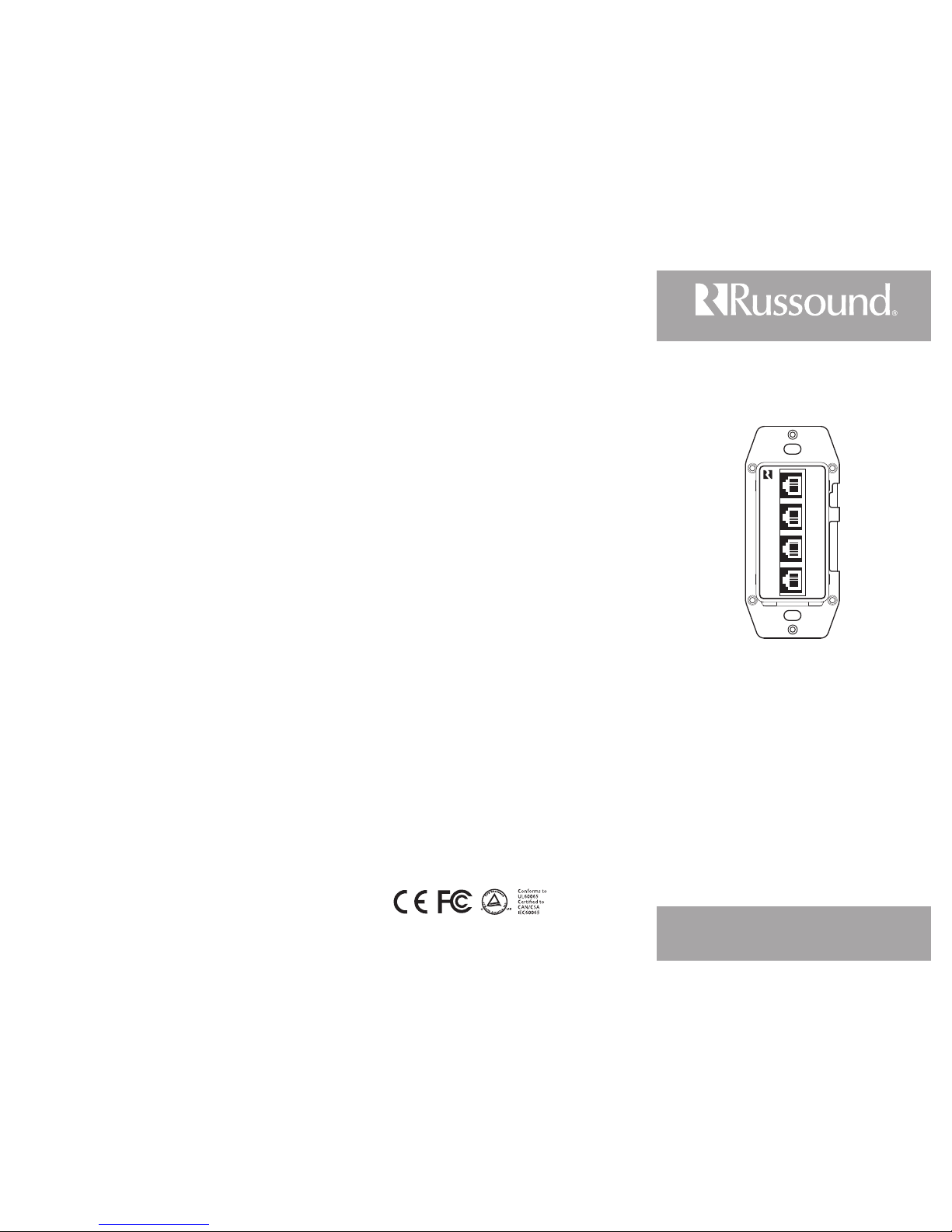
CA4-WP
CA4 Wall Port
Installation Manual
Overview
The Russound CA4-WP Wall Port provides a connection between
the C A4 controller and the CA-KP keypads. It is mounted near the
controller in a single-gang electrical box.
Specications
Dimensions: 1.9" x 1.9" x 4.1" ( 49 x 49 x 105mm)
Weight: 0.25 lb. (0.11kg)
Keypad ports: 4
Keypad Cables: CAT-5 - RJ-45 termination
Speaker connections: 4
Speaker Cables: 14-18 gauge - screw termination
Max cable length: Wall Port to controller 6' (2m)
Wall Port to keypad 240' (73.2m)
Wall Port to speaker 240' (73.2m)
Safety Instructions
1. Read Instructions - All the safety and operating instructions should be read
before the appliance is operated.
2. Retain Instructions - The safety and operating instructions should be
retained for future reference.
3. Heed Warnings - All warnings on the appliance in the operating instructions
should be adhered to.
4. Follow Instructions - Follow all operating and user instructions.
5. Water and Moisture - The appliance should not be used near water;
for example, near a bathtub, washbowl, kitchen sink, laundry tub, in a wet
basement, or near a swimming pool.
6. Wall Mounting - The appliance should be mounted to a wall as
recommended by the manufacturer.
7. Heat - The appliance should be situated away from heat sources such as
radiators, heat registers, stoves, or other appliances (including ampliers) that
produce heat.
8. Power Sources - The appliance should be connected to a power supply
only of the type described in the operating instructions or as marked on the
appliance.
9. Grounding or Polarization - Precaution should be taken so that the
grounding or polarization means of an appliance is not defeated.
10. Object and Liquid Entry - Care should be taken so that objects do not fall
and liquids are not spilled into the enclosure through the openings.
11. Damage Requiring Service - The appliance should be serviced by qualied
service personnel when:
The power supply cord or the plug has been damaged;
Objects have fallen, liquid has been spilled into the appliance;
The appliance has been exposed to rain;
The appliance does not appear to operate normally; or
The appliance has been dropped or the enclosure is damaged.
12. Servicing - The user should not attempt to service the appliance beyond
that described in the operating instructions. All other servicing should be
referred to qualied service personnel.
13. Care – From time to time you should wipe o the front panel with a soft
dry cloth.
Limited Warranty
The Russound CA4-WP is fully guaranteed for two (2) years from the date
of purchase against all defects in materials and workmanship. Dur ing this
period Russound will replace any defective parts and correct any defect in
workmanship without charge for either parts or labor. For this warranty to
apply, the unit must be installed and used according to its written instructions.
If service is necessary, it must be per formed by Russound. Russound assumes
no responsibility for defects resulting from abuse or servicing performed by an
agency or person not specically authorized in writing by Russound. Damage to
or destruction of components due to improper use voids the warranty. In these
cases the repair will be made at the owner’s expense. Accidental damage and
shipping damage are not considered defects under the terms of the warranty.
To return for repairs, the unit must be shipped to Russound at the owner’s
expense, along with a Return Authorization number and documentation
explaining the nature of the service required. Any product returned without
prior written permission will be returned to sender. Russound sells products
only through authorized Dealers and Distr ibutors to ensure that customers
obtain proper support and service. Any Russound product purchased from an
unauthorized dealer or other source, including retailers, mail order sellers and
online sellers will not be honored or serviced under existing Russound warranty
policy. Any sale of products by an unauthorized source or other manner not
authorized by Russound shall void the warranty on the applicable product.
Copyright ©2010 Russound® All rights reserved. All trademarks are
the property of their respective owners. Russound is not responsible for
typographical errors or omissions. Specications are subject to change without
notice.
Russound, Inc. 5 Forbes Rd., Newmarket, NH 03857, USA
tel 603.659.5170 • fax 603.659.5388 www.russound.com
Technical support: 866.888.7466 e-mail: tech@russound.com
KAW 02/03/10
Wall Port Installation
Pick an unobtrusive location close to the controller that 1.
all cables (speaker and keypad) can be routed to.
Install an electrical box, using a UL/CSA approved plastic 2.
single-gang (18 ci or deeper) electrical box. If there will
be two controllers you should use two single-gang
boxes separated slightly to allow space for the cables.
Route CAT-5 wire from the electrical box to the four keypad 3.
locations. Route the speaker cable from the electrical box
to the corresponding speaker locations. Label each set of
cables with the zone and location.
Terminate each CAT-5 wire with a RJ-45 plug using the 4.
T568A standard conguration.
Strip 1 to 2 inches (2.5 to 5 cm) o the end of each speaker 5.
cable jacket. Then strip 1/4 inch (0.7 cm) of insulation o
each wire.
Twist the speaker wire strands together so there are no 6.
strands separated from the bundle.
Insert the proper speaker wire, matching channel 7.
and polarity for all four wires. Tighten the screws until
the wires are secured in the terminal.
Cable as follows (standard 4-conductor):
White -- L+ (left channel positive), Green -- L- (left channel
negative), Black -- R- (right channel negative) and Red -R+ (right channel positive).
Check to make sure there are no stray strands of wire 8.
outside the terminals. If there are, remove the wire, twist
the strands together, and reconnect the wire to the
terminal.
Complete the same steps for the remaining zones. Plug 9.
each of the RJ-45 plugs into the corresponding keypad
zone jack on the rear of the wall port. Note: All four
connections from the controller to the wall port must be
made, even if there are less than 4 keypads connected
to the system. Cables between the wall port and the
controller must match numerically (#1 on the wall port
to #1 on the controller).
Mount the wall port in the electrical box. Push any extra 10.
cable back into the wall. Screw the wall port plate to the
electrical box. Attach the trim plate to the wall port.
1
2
3
4
Page 2
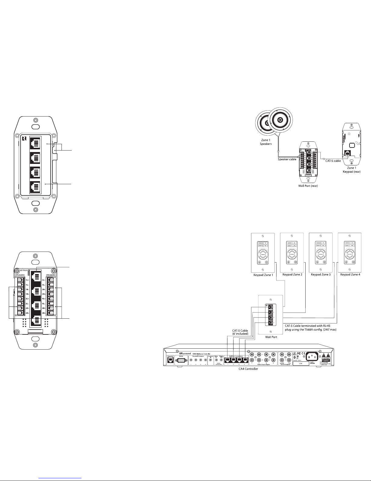
CA4 Wall Port (rear)
Speaker terminals
Four pair 8 ohm speakers
Two channels each
RJ-45 Keypad Connections
Connect to each keypad
RJ-45 Connections
Use included CAT-5 cables
to connect the controller
to the Wall Port.
CA4 Wall Port (front)
1
2
3
4
When changing face plate
colors, the plate cutouts
must be on the same side
as the zone numbers
Wall Port Front and Rear
Speaker Outputs
The CA4 supports speaker outputs for zones 1 through 4 for
each controller with a maximum of eight zones. Each speaker
connection requires a 8-ohm load and will provide 15 watts
per channel. Standard 16-gauge 4-conductor stranded
speaker wire can be run up to 125 feet; 14-gauge wire can be
run up to 250 feet.
The speakers are connected to the CA4 Wall Port using xed
screw terminals. Each of these terminals is designated for the
speaker set of a particular amplied zone. To avoid confusion,
connect one zone speaker set at a time starting with Zone 1,
taking care to keep zone and speaker wire identities straight.
Controller / Keypad Conguration
The CA4 Wall Port jacks are located on the rear of the
controller. These RJ-45 ports must be connected to the
corresponding jacks on the wall port. Each keypad is then
connected to the wall port.
All CAT-5 connections are made with RJ-45 connectors
using the T568A Wiring Standard conguration. For a clean
installation use the included RJ-45 CAT-5 pass-through
cables to connect from the controller wall port jack to the
corresponding one on the CA4-WP. Using the same wiring
conguration to terminate the ends, route a CAT-5 cable
from the wall port to each of the keypads. Cables from the
controller to the wall port should not exceed 6 feet (2m).
The maximum recommended CAT-5 cable length is 240 feet
(73.2m) between the wall port and the keypad.
Note: All four CAT-5 cables must be connected between the
controller and wall port for proper operation.
Caution: Cables between the wall port and the controller
must match numerically (#1 on Controller to #1 on Wall Port,
etc.). Swapping cables to dierent ports can damage the
equipment.
 Loading...