

Russound AW70V6 Installation Manual
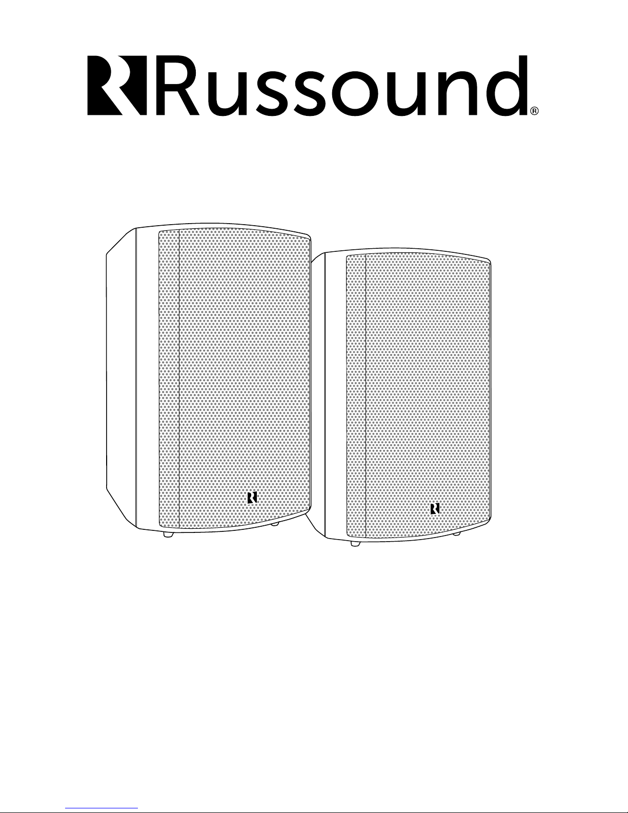
70V Surface Mount Indoor/Outdoor Speakers
AW70V6
Installation Manual
SPEAKER ASSEMBLY INTRODUCTION
Introduction
Thank you for selecting the AW70V6 speakers from Russound.
The AW70V6 speakers are designed to add high quality,
custom-tailored sound for distributed audio systems using
either 70V or 100V amplication. With an easily adjustable
weatherproof tap setting switch on the rear panel, these
versatile speakers even include a bypass setting to allow their
use as high performance 6-ohm speakers. Their 1” titanium
dome tweeters combined in a ported-cabinet design with 6.5”
injection-molded polypropylene woofers, provide the audio
quality that our customers have come to know and expect
from Russound, while rugged enough for even the most
extreme outdoor environments.
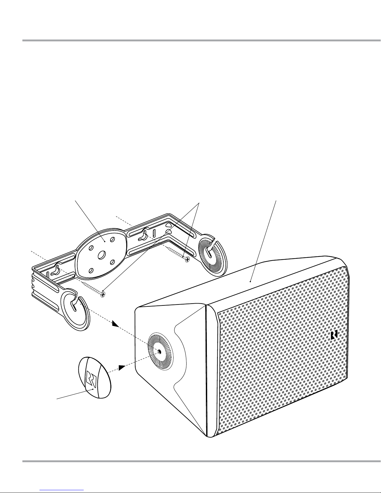
Bracket
Speaker assembly
The bracket has screw slots to accommodate either wall,
ceiling and pole-mounted installation options. A "C-slot"
bracket design allows for one-handed installation by allowing
the bracket to support the speaker's weight until it is locked
into position. Custom, easy-to-turn, weather-resistant knobs
provide a versatile and cosmetic nish for the brackets'
attachment points.
Mounting Screws
(Not included)
Speaker
Mounting Knob
2 Russound AW70V6 70V Surface Mount Indoor/Outdoor Speaker Installation Manual
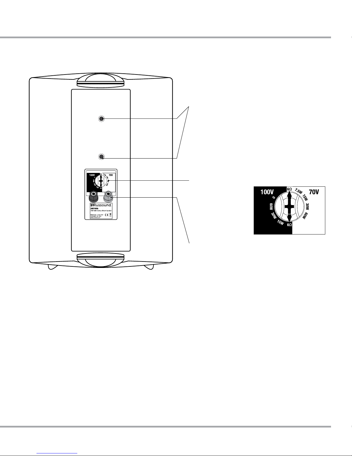
SPEAKER BACK PANEL
1/4"- 20 Brass Inserts - ts many aftermarket mounting
systems if desired. Follow directions included with the
aftermarket product.
Tap Setting Knob - for easy adjustment of the tap settings
with options for:
7.5W, 15W, 30W, 60W (70V)
15W, 30W, 60W (100V)
6Ω Bypass
Binding Posts - to secure speaker wire, up to 12 gauge.
Russound AW70V6 70V Surface Mount Indoor/Outdoor Speaker Installation Manual 3
WIRING INFO 70V/100V OPERATION
Speaker cable
Wiring speakers for 70V/100V systems is simple and easy. A
single run of 2-conductor, stranded wire is run to every speaker
location leaving a small loop (2-3 feet is usually more than
sucient depending on the speakers and their mounting type)
at each speaker location. You can place additional loops for
future expansion or for making speaker location changes if
needed.
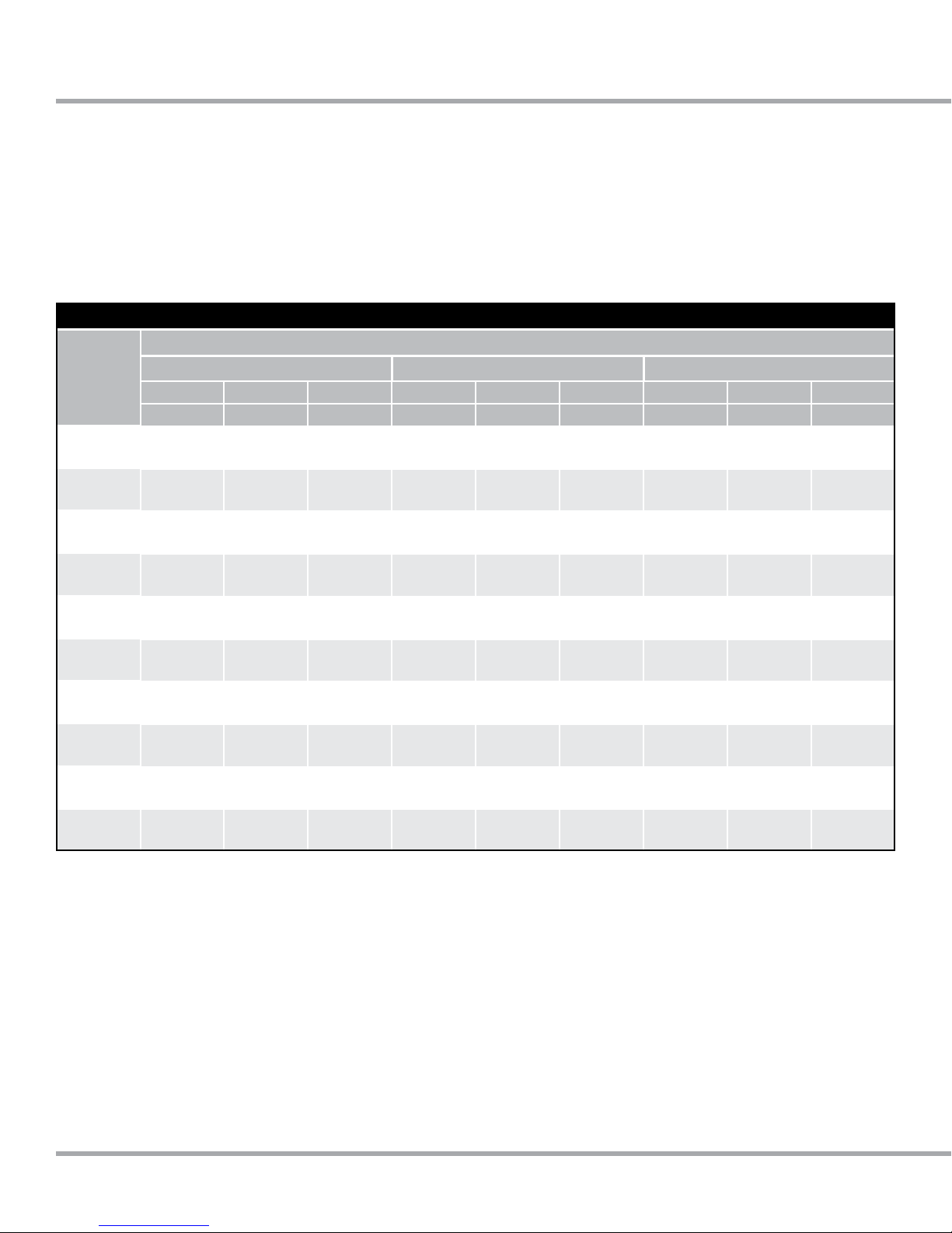
Speaker Cable Length for Various Gauges at Low and High Impedance
Power Loss in Cable (% Loss & dB Loss)
4 Ohm Speakers 8 Ohm Speakers 70V Speakers
AWG
6
8
10
12
14
16
18
20
22
24
11% 21% 50% 11% 21% 50% 11% 21% 50%
0.5 dB 1 dB 3 dB 0.5 dB 1 dB 3 dB 0.5 dB 1 dB 3 dB
277’
84m
174’
53m
110’
33.5m
69’
21m
43’
13m
27’
8m
17’
5m
11’
3m
7’
2m
4’
1m
571’
174m
359’
109m
226’
69m
142’
43m
89’
27m
55’
17m
35’
11m
22’
7m
13’
4m
9’
3m
1930’
588m
1214’
370m
764’
233m
480’
146m
302’
92m
185’
56m
117’
36m
74’
23m
46’
14m
29’
9m
554’
169m
349’
106m
219’
67m
138’
42m
87’
27m
53’
16m
34’
10m
21’
6m
13’
4m
8’
2m
Note: This is very dierent from typical low-impedance wiring
used for residential audio installations where a dedicated run
of wire goes from each speaker back to the amplier/receiver.
70V/100V wiring uses much less wire and the wire used can be
a much higher gauge (thinner wire) even though it is used in a
longer run.
Here is a chart showing some of the dierences possible
among wire lengths for both low impedance (4Ω-8Ω) and high
impedance (70V/100V) systems:
1141’
348m
718’
219m
452’
138m
284’
87m
179’
55m
110’
38m
69’
21m
44’
13m
27’
8m
17’
5m
3859’
1.2km
2428’
740m
1528’
466m
959’
292m
604’
184m
371’
113m
234’
71m
147’
45m
91’
28m
57’
17m
2.6mi
4.14km
1.6 mi
2.6km
1mile
1.6km
3376’
1km
2127’
648m
1305’
398m
823’
251m
518’
158m
321’
98m
202’
62m
5.3mi
8.5km
3.4 mi
5.5km
2mi
3.4km
1.3 mi
2.1km
4380’
1.3km
2687’
819m
1694’
516m
1068’
331m
661’
201m
417’
127m
18mi
29km
11.3 mi
18.1km
7mi
11.4km
4.5mi
7.2km
2.8mi
4.5km
1.7mi
2.8km
1mi
1.75km
3610’
1.1km
2234’
681m
1409’
429m
Note: Unlike traditional residential audio, 70V/100V systems
are typically run in mono sound so that only a single twoconductor wire run is necessary for the speakers. If you want
to use multiple wire runs for zoning speakers or other purposes,
each 2-conductor wire needs to be independently run back to
its own amplier or amplier terminals if using a multi-channel
amplier.
1. At each speaker location, cut the loop of wire at the speaker
location
2. Strip 1 to 2 inches (2.5 to 5 cm) o the end of the cable jacket.
Then strip ½-inch (1.3 cm) of insulation o each wire.
3. Twist the wire strands together so there are no strands
separated from the bundle.
4. Connect the wires to the speaker terminals, being sure to
4 Russound AW70V6 70V Surface Mount Indoor/Outdoor Speaker Installation Manual
observe proper polarity. For standard speaker cable with red
and black wires, connect both red wires (the red wire coming
from the 70V/100V connection on the amplier or the previous
speaker if there was one AND the red wire going to the next
speaker if there is an additional speaker) to the red positive
(+) terminal and both black wires (the black wire coming from
the COM connection of the 70V/100V amplier or the previous
speaker if there was one AND the black wire going to the next
speaker if there is an additional speaker) to the black negative
(–) terminal.
Note: Some speaker cables may have other ways of designating
polarity. Cable with a clear jacket has a copper-colored wire for
positive and a silver-colored wire for negative. In a cable with
white and black wires, the white is positive (70V or 100V) and
the black is negative (COM). Cable with both wires the same
 Loading...