

Page 1

English
JrBUS
-Model
In-Wall,
for
Instruction Manual
A-BUS
The
Multi-Room Audio
other essential components
etc.),
high-quality
A-BUS
to remote locations with a single 8-conductor cable
technology provides many advantages over other methodsofaudio distribution, including: simple, single
components; infrared controlofthe optional
and
Every
th
1.
2.
3.
SYSTEM
product you
OVERVIEW
have
just
purchasedisan
System.Itis
and
creates
a versatile whole-house audio
sound
for
yearstocome.
technologyisa
new,
innovative methodofproviding high quality audio
CAT-5
system
power status.
A-BUS
Systemiscomprisedofcomponents from
ree
areas.
A-BUS Amplified Modules:
room's
speakersaswellasthe control for those
be
used
for
each
should
Amplified
Control
Keypad
are
examplesofA-BUS
room you
(with built-inIRreceiver)
A-BUS Hubs: All componentsofthe
to a Hub located near your source equipment.
nection
for
source
equipment, volume controls, infrared emitters
supply.
The
A-H484, A-H4, A-H4D,
The
A-H484, A-H4,
wall
Decora©
Power Supply:
24VDC!4A
unitisan
and
A-H2
style unit.
The
power supply plugs into the
example.
l~Russound
5
Forbes
Rd.
-a-
Newmarket,NH03857,
603.659.5170 •
e-mail:
tech@rllssound.com
Fax
603.659.5388
A-H4D
4-Zone
A-BUS
a component which, when combined with
your
source
wiring
The
Module contains both the amplifier for the
choose
Amplified
A-BUS
and
are
surface-mount units.
Come
visitusat:
Hub
System
integral partofthe
equipment
system
scheme;
A-KP2
to control.
and
Modules~
A-H2
USA
(receiver,CDplayer,
that will fill your rooms with
suchasCAT-5.
infrared controlofsystem
amplified
eachofthe following
speakers.
The
A-VC2
system
mustbewired centrally
The
Hub provides the con-
are
examplesofA-BUS
Hub.
The
Russound
A-BUS
keypad
module;
One
Module
Russound
Amplified Volume
and
The
A-H4Disan
Russound
A-BUS
A-KP2
power
Hubs.
A-PS
in-
A-H4D
The
Hub
date4additional
Expansion Hub,
IMPORTANT - Before
with
the
professional
A-H4D
1)
2) 4
3)
4) Power
5)
6)
6) Decora®
7)
A-H4D
Power
Status
Keypad
Link
I
Expansion
I
I
Emitter
I
I
Dimensions:
I
I
I
Weight:
I
I
I
I
I
I
I
I
I
I
I
I
I
I
I
I
I
I
I
I
I
I
I
I
I
I
I
I
I
I
I
I
I
I
I
I
I
r
I
I
I
I
I
OVERVIEW
A-H4Disan
used
each
installation
KEY
1 source
commonIRoutputs
Status
Link In
Plug-in
Front-panel
and
Status
A-BUS
in-wall,
with
A-BUS
Amplified
Amplified
which
plugs
installation,
componentinyour
procedures described
electronics
installer.
FEATURES
audio
input
and
power
input
with
input
and
Out
connection
faceplate
connections
for
(2-gang)
4-zone,
l-source
Modules. The
Modules
into
when
the
sideofthe
review
the
system.Ifyou
hereinorelsewhere,
loop
output
selector
A-H4Dx
for
jumper
Expansion
Audio,IREmitters, Power,
SPECIFICATIONS
Supply:
Power:
Connection:
Connection:
Connection:
Connections:
LIMITED WARRANTY
The
Russound
all
defectsinmaterials
tive
For
instructions.Ifserviceisnecessary,itmustbeperformedbyRussound.
returnedtoRussoundatthe
damage
Russound
byanagencyorperson
destructionofcomponents
willbemadeatthe
Russoundatthe
required.Besuretopackina
rialtoprotect
A-H4Disfully
parts
and
this
correct
warranty to
and
shipping
assumesnoresponsibility
owner's
the
unit from
A-PS. 24VDC/4A.
12VDC/l00mA.
CAT-5, 110
CAT-5, 110
8-pin
1/8" Male. Tip
3.54"W
8 oz. (226g)
guaranteed
and
workmanship.
any
defectinworkmanship
apply,
the
unit
owner's
damage
are
not
not
owner's
for
specifically
duetoimproper
expense.Toreturn
expense,
along
corrugated
damageintransit.
Punchdowns
Punchdowns
female
connector
(+),
x 2.91"H x
for
Two
(2)
During
mustbeinstalled
expense
considered
defects
authorizedinwritingbyRussound.
with a
container with at
years
this
period
without
and
with prior written
defects
resulting
use
voids
for
note
the
repairs,
explaining
Audio
Distribution
A-H4D
used
with
can
the
A-H4D.
manuals
included
are unsureofany
(on rear)
Hub
sleeve H
1.456"0
from
and
under
from
warranty.Inthese
(90x74x37mm)
the
dateofpurchase
Russound
will
charge
used
abuseorservicing
the
least3inchesofresilient
replace
for either
accordingtoits
The
permission.
the
termsofthe
unit
mustbeshipped
the
natureofthe
accomo-
A-H4Dx
of
consult
against
any
defec-
partsorlabor.
written
unit
must
Accidental
warranty.
performed
Damagetoor
cases
the
repair
service
mate-
a
be
to
Page 2
INSTRUCTIONS
II
AMPLIFIED
FOR
CONNECTING
MODULES
AND
USING
RUSSOUND
II
MODEL
A-H4Dx
A-H4D.
REFERTOTHE
EXPANSION
HUB
DIAGRAMS
INSIDE.
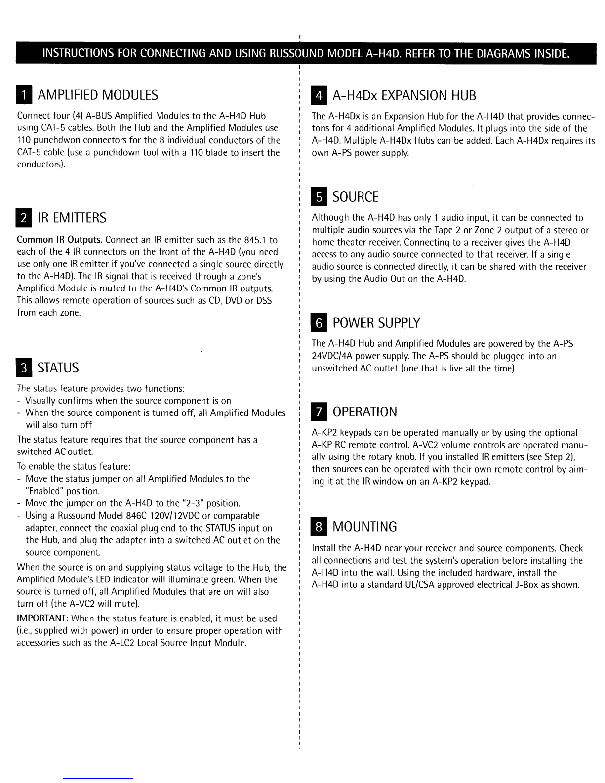
Connect
using
110
CAT-5
conductors).
IIIR
CommonIROutputs. ConnectanIR
eachofthe 4IRconnectors on the
use
to the A-H4D).
Amplified Module
This
from
II
The
- Visually confirms when the source component
- When the source component
The
switched
To
- Move the status jumper on all Amplified Modules
- Move the jumper
- Using a
When the source
Amplified Module's
source
turn
IMPORTANT: When the status feature
(i.e.,
accessories
four
(4)
A-BUS Amplified Modules to the A-H4D Hub
CAT-5
cables.
Both the Hub
punchdwon connectors
cable
(use
a punchdown tool with a
and
the Amplified Modules
for
the 8 individual conductorsofthe
110
blade to insert the
EMITIERS
emitter suchasthe
frontofthe A-H4D (you
only
oneIRemitterifyou've connected a single source directly
TheIRsignal
is
routedtothe A-H4D's CommonIRoutputs.
allows remote operationofsources suchasCD,
each
zone.
thatisreceived through a zone's
STATUS
status feature provides
also
turn
will
status feature requires
enable the status feature:
"Enabled" position.
adapter, connect the coaxial plug
the
Hub,
source component.
is
off
supplied with power) in order to ensure proper operation
off
AC
outlet.
on
Russound
and plug the adapter into a switchedACoutletonthe
isonand supplying status voltagetothe
LED
turned off, all Amplified Modules
(the A-VC2 will mute).
suchasthe A-LC2
two
functions:
is
is
turned off, all Amplified Modules
that
the source component
the A-H4D to the "2-3" position.
Model 846C 120V!12VDC or comparable
endtothe
indicator will illuminate green. When the
is
Local
Source Input Module.
STATUS
that
areonwill also
enabled,itmustbeused
845.1
DVDorDSS
on
has
a
to
the
input
Hub,
use
to
need
on
with
the
The
A-H4Dxisan
for
tons
A-H4D. Multiple A-H4Dx Hubs
own A-PS power supply.
II
Although the A-H4D
multiple audio sources
home theater receiver. Connecting to a receiver gives the A-H4D
access
audio source
by using the Audio Out
II
The
24VDC!4A power supply.
unswitchedACoutlet
II
A-KP2 keypads
A-KP
ally using the rotary knob.
then sources
ingitat
II
Install the A-H4D near your receiver and source components. Check
all connections and test the system's operation before installing the
A-H4D into the wall. Using the included hardware, install the
A-H4D into a standard
4 additional Amplified Modules.Itplugs into the sideofthe
SOURCE
to any audio source connectedtothat
POWER
A-H4D Hub and Amplified Modules
OPERATION
RC
remote control. A-VC2 volume controls
theIRwindow onanA-KP2 keypad.
MOUNTING
Expansion Hub
has
only 1 audio input,itcanbeconnected to
via
is
connected directly,itcanbeshared
on
for
canbeadded.
the
Tape
the A-H4D.
the A-H4D
2 or Zone 2
that
provides connec-
Each
A-H4Dx requires its
outputofa stereo or
receiver.Ifa single
with
the receiver
SUPPLY
are
powered by the A-PS
The
A-PS shouldbeplugged into
(one
thatislive all the time).
canbeoperated manually or by using the optional
are
If
you installedIRemitters
canbeoperated with their own remote control by
UL!CSA
approved electrical J-Boxasshown.
an
operated manu-
(see
Step
2),
aim-
Page 3
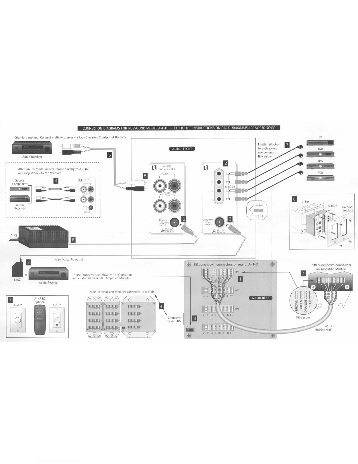
CONNECTION
DIAGRAMS
FOR
RUSSOUND
MODEL
A-H4D.
REFERTOTHE
INSTRUCTIONSONBACK.
DIAGRAMS
ARE
NOTTOSCALE.
Standard method:
Connect
multiple
sources
via
Tape2or
Zone
2 outputofReceiver
CD
Decora®
faceplate
DSS
VCR
DVD
110
punchdown connectors
on Amplified Module
J-Box
Emitter attaches
to
each
source
component's
IR
window
l1
+12V=-=-=
200mA
+~-
V+v-L+L-R+R-IR
5T
110
punchdown connectors on rear of A-H4D
·'I:G
ili
i
3
,'h-
POWER
+24V=-=-=
4A+~-
A-H4D
Connection
Hub
rAUDIOIN,
~!i
~@
l1
o 0
o 0
A-H4Dx
Expansion
Modules
~~to~H4D
~
Connector
mQIDl
for
A-H4Dx
-~
~.:.
a.
~~~~O
A-BUS
To
use
Status
feature:
Move
to
1/2-31/
position
and
enable
statusonALL
Amplified Modules
-------------+---,
to switchedACoutlet
A-KP2
~
"0
Id
~
o
Audio
Receiver
A-KP
RC
(optional)
Audio
Receiver
Alternate method:
Connect
source
directlytoA-H4D
and
loopitbacktothe
Receiver
o
o
Audio
Receiver
•
A-VC2
Page 4

1Vrms
+24VDC,20mA
3to60 seconds
RJ45
connector
3.5mm mono
IR
output
jack
1.75"W x2.875"H x 1.75"D
(45x73x45mm)
3.5
oz.
(100g)Weight:
Input Sensitivity:
Power Requirements:
Switching Delay:
CAT-5
Connections:
IR
Emitter Connection:
Dimensions (in-wall):
A-LC3
Features
Auto turnONof
zone when used
with
A-K5L
keypad
IR
emitter
output
forIRcontroloflocai source
Stereo audio input
Automatic switching between local and main source
Switching sensitivity adjustment
Switching delayadjustment
A-LC3
Specifications
A-LC3
Local
Input
Module
for
A-BUS'
System
Installation
Manual
A-LC3
Overview
The Russound
A-LC3isan
in-wall local source
input
mod-
ule used
with
A-BUS· hubs and controllers in a distributed
audio system.
An
A-LC3
in a room lets a local source or
portable audiocomponent be heard over the room's
speakers independently from other rooms in
the
A-BUS
system.
The
A-LC3
connects between the
A-BUS
hub/controller
and
an
A-BUS
amplified keypad
via
CAT-5
cable. The
A-
LC3
automatically selects betweenanindependent local
source
(e.g.,
portableCDplayer) and the sourceofan
A-BUS
system. It
can
be used
with
both single- and multi-
source
A-BUS
hubs/controllers.
This product
maybecoveredbyone or moreofthe following
patents:
US
#7,181,023, #6,389,139;EP#1004222,AU#739808,
NZ
#502982,
Mexico
#241196,
Canada
#CA2301062
A-BUSisa registered trademark of
LeisureTech
Electronics Ply
Ltd Australia
l~Russound~
28-1272 Rev. 1
04/01/08
5
Forbes
Rd.
Newmarket,NH03857,
USA
Tel
603.659.5170 •
Fax
603.659.5388
e-mail:
te<h@russound.(om
Safety
Instructions
1.
Read
Instructions-All
the
safety
and
operating
instructions
should
be
read
before
the
applianceisoperated.
2. Retain Instructions· Thesafety and operating instructions should
be
retained
for
future
reference.
3.
Heed
Warnings-All
warningsonthe
applianceinthe
operating
instructions
shouldbeadhered
to.
4.
Follow
Instructions-All
operating
and
user
instructions
should
be
followed.
5.
Water
and
Moisture'
The
appliance
should
notbeused
near
water;
for
example,
near
a bathtub,
washbowl,
kitchen
sink,
laundry
tub,
in
a wet
basement,ornearaswimming
pool.
6.
WallorCeiling
Mounting *
The
appliance
shouldbemountedtoa
wallorceiling
onlyasrecommendedbythe
manufacturer.
7.
Heat -
The
appliance
shouldbesituated
away
from
heat
sources
suchasradiators,
heat
registers,
stoves,orother
appliances
(includ-
ing
amplifiers)
that
produce
heat.
8.
Power
Sources-The
appliance
shouldbeconnectedtoa
power
supply
only
ofthe
type
describedinthe operating
instructionsoras
markedonthe
appliance.
9.
GroundingorPolarization-Precaution
shouldbetakensothat
the
groundingorpolarization
meansofan
applianceisnot
defeated.
10.
Object
and
liquid
Entry*Care
shouldbetakensothat
objects
do
not
fall
and
liqUids
are
not
spilled
into the
enclosure
through the
openings.
11.
Damage
Requiring
Service*The
appliance
shouldbeserviced
by
qualified
service
personnel
when:
The
power
supply
cordorthe
plug
has
been
damaged;
Objects
have
fallen,
liquid
has
been
spilled
into the
appliance
The
appliance
has
been
exposedtorain
The
appliance
does
not
appear to operate
normally
The
appliance
has
been
droppedorenclosureisdamaged.
12.
Servicing-The
user
should
not
attempt to
service
the
appliance
beyond
that
describedinthe
operating
instructions.
All
other
servic-
ing
shouldbereferredtoqualified
service
personnel.
13.
Care-From
timetotime
you
should
wipe offthe
front
panel
with a
soft
dry
cloth.
Limited
Warranty
The
Russound
A-LOisfully
guaranteed
for
two
(2)
years
from
the
dateofpurchase
against
all
defectsinmaterials
and
workmanship.
During
this
period
Russound
will
replace
any
defective
parts
and
correct
any
defectinworkmanship
without
charge
for
either
partsorlabor.
For
this
warrantytoapply,
the
unit
mustbeinstalled
and
used
accordingtoits
written
instructions.Ifserviceisnecessary,itmustbeperformed
by
Russound.
Russound
assumesnoresponsibility
for
defects
resulting
from
abuse
or
servking
performedbyan
agencyorperson
not
specifically
authorizedinwriting
by
Russound.
Damagetoor
destructionofcomponents
duetoimproper
use
voids
the
warranty.
In
these
cases
the
repair
will
be
madeat
the
owner's
expense.
Accidental
dam·
age
and
shipping
damage
are
not
considered
defects
under
the
termsofthe
warranty.
To
return
for
repairs,
the
unit
mustbeshippedtoRussoundatthe
owner's
expense,
along
withaReturn
Authorization
number
and
documentation
explaining
the
nature
d
the
servke
required.
Any
produet
returned
without
prior
written
permission
will
be
returnedtosender.
Russound
sells
products
only
through
authorized
Dealers
and
Distributorstoensure
thatcustomers
obtain
proper
support
and
service.
Any
Russound
product
purchased
fromanunauthorized
dealer
or
other
source,
including
retailers,
mail
order
sellers
and
online
sellers
will
notbehonoredorserviced
under
existing
Russound
warranty
policy.
Any
saleofproductsbyan
unauthorized
sourceorother
manner
not
authorizedbyRussound
shall
void
the
warrantyonthe
applicable
product.
Qrlmn,1D
Ul6500
CetifiOOID
CANC5A
The 3.5mm
monoIRoutput
jackisusedtoconnect
a Russound
IR
emittertoa local source and transmit
commands from
the
A-BUS
keypadtothe local source
if
remotely located (suchasa closetorcabinet). When
the
local source
inputisactive,
alliR
codes sent
through
the
keypad will be routedtotheIRemitter
outputonthe
A-LC3
(these commands will also be senttotheIRoutput
of
the last source selectedbythat
keypad andtothe
Common
IR
outputonthe
hub/controller,
not
routed
onlytothe
A-LC3).
Copyright ©
2008
Russound'
All
rights reserved.
All
trademarks
are
propertyoftheir
respective
owners.
Russoundisnot
respon~
sible for typographical errors or omissions. Specifications
sub-
ject tochange without notice.
7
IR
Output
Jack
for
Local
Source
8 Installation
Check all connections and test
the
system's operation
before installing the
A-LC3
into
the
wall. Using
the
included hardware, install
the
A-LC3
into
a standard ULI
CSA
single-gang electrical J-box.
9
Auto
ON/OFF
with
A-K5L
The
A-LC3
allows a local sourcetoplay
through
that
room's speakers, insteadofwhat's playingonthe main
source, and its volume
is
controlled using
that
room's
amplified keypad.
When
the
local sourceisactivated,
the
A-LC3
automatically turnsON(ifitis
OFF)
the
A-K5L
keypad
in the zone.
Ifthe
keypadison,
when
the
local source
becomes active
it
overrides the main source audio in
that
room, and when inactive, returns
the
roomtothe
main
source audio.
When the
A-LC3isactive
with
the
A-K5L keypad,
the
local source will
turn
the
keypadONto
a
preprogrammed volume. This value (LsVol)
is
set in
the
A-K5L
programming menu.
The
A-K5L
LCD
screen displays
"Ls
On"toindicate the
local source
has
turned
the
zone on.Ifthe
keypad
is
turned
off
but
the
local source
inputisstill active, the
keypad returns
to
the
"Ls
On" state.
When the
A-LC3
loses the signal (no audio present on
the
line level inputs),
the
A-LC3
turns
off
the
A-K5L.
The
zone status
LED
remains
lit
until
the
A-K5Lispower
cycled.
CONNECTION
INSTRUCTIONS
FOR
A-LC3.
REFERTONUMBERED
DIAGRAMONREVERSE.
1
RJ45
Connector
for
CAT-5
(Hub/Controller) 6
Line
Level
Input
for
Local
Source
The
RJ45
"Hub"
input
provides a connection
for
the
The Line Input with autosensing gold-plated stereo
RCA
CAT-5
cable from an
A-BUS
hub/controller.
Use
the
jacks provides a stereo line-level audio
input
foralocal
T568A
wiring
standard. The recommended
maximum
source with an
RCA
cable connection.
length for standard
CAT-5
cableis150 feet. Before
connecting the
A-LC3,
disconnect
the
power supply
from the
A-BUS
hub/controller
and disconnect
the
Status
power supply
if
used.
4
Adjustment
for
Switching
Delay
The rotary
trim
potentiometer
provides adjustment
of
source switching delay. This adjustment determines
the
timeittakestoreturntothe
main source after
the
local source signalisno longer detected. Fully
counter-clockwise
is
the
lowest level; turn
the
trim
screw
clockwise
until
switching occurs.
3
Adjustment
for
Switching
Sensitivity
The rotary
trim
potentiometer
provides adjustment
of
source switching sensitivity. This adjustment determines
the level
of
signal
that
must
be present before the
A-LC3
will switch from
the
main sourcetothe
local source. Fully
counter-clockwise
is
the
lowest level; turn
the
trim
screw
clockwise until switching occurs.
2
RJ45
Connector
for
CAT-5
(Keypad)
The
RJ45
"Keypad"
input
provides a connection
for
the
CAT-5
cabletothe
amplified keypad.
Use
the T568A
wiring standard. The recommended maximum
length
for standard
CAT-5
cableis150 feet. Before connecting
the
A-LC3,
disconnect
the
power
supply from
the
A-BUS
hub/controller and disconnect
the
Status
power
supply
if
used.
5
Sensitivity
and
Switching
Delay
LED
The green
LED
indicator nexttothe
sensitivity
adjustment control helps the installer set the levels
during installation.
When
the
A-LC3ispoweredbythe
hub/controller
(through
RJ45
connection),
the
LED
flashes three times
to
confirm
hub
connection. This takes
1.5
seconds,
during which
time
the
local source will
not
be looking
for external audio. After this period, normal operation
is
initiated, andifany external audioissenseditwill be
routed
to
keypads. This short power-up delay also allows
A-K5L
keypadstoproperly
boot
up.Itis
important
not
to
send any codestoit
beforeitis
fUlly on-line,asthe
system couldgooutofsync.
The
LED
turns on
when
the
A-LC3
switchestothe
local
source input.
Use
the
sensitiVity adjustment
with
local
source audio present
until
the
LEDisjust
above steady
ON,
then turn the sensitivity adjustment and additional
1/8th turn.
Page 5

CONNECTION
DIAGRAM
FOR
A-LC3.
REFERTOTHE
NUMBERED
INSTRUCTIONSONREVERSE.
DIAGRAMS
ARE
NOTTOSCALE
.
=
Local
source
-
Satellite receiver
A-C68
controller
RCA
cables
~,.
•.....
of..
8-ohm speakers
~I.O
"""0
o:\.Y~",'
0
•.
~::~
A-LRC2
~
remote
control
IR
emitter
CAT-S
cable
A-KSL
~~8----'O~AT-5r----cable
_~
~[je
Speaker (
(;7
@ cable ®
.-
MaxCAT-5
length
of
750
feet
IROUT
@
rAUDIOIN,
~~
A-LC3
(front)
A-LC3
(back)
o
A-LC3
(side)
RJ-45
usingT568A Wiring Standard
12345678
iiiIiii
I
A-KSL
(back)
L _
...£Oo~~.~
.~~
.-0--.
CAT-S
cable
A-H484 alternate
hub choice
Page 6

PressOKto
PressOKto
option.
Performs
option.
Performs
devices.
l~Russound®
l~Russound®
A-LRC2
A-LRC2
A-BUS®
A-BUS®
PRE-PROGRAMMED
PRE-PROGRAMMED
INTRODUCTION
INTRODUCTION
The
A-LRC2
The
A-LRC2
with
Russound
with
Russound
operate
source
operate
source
pad.
The
A-LRC2
pad.
The
A-LRC2
A-BUS
sources
A-BUS
sources
results,
please
results,
please
instructions
instructions
FEATURES
FEATURES
Note:SI-
S6,
Note:SI-
S6,
commands
and
commands
and
other
buttons
other
buttons
associated
with
associated
with
devicetodevice.
devicetodevice.
The
following
The
following
tionofbutton
tionofbutton
Key
Charts
Key
Charts
Turn
Turn
talkback
talkback
confirmation.
confirmation.
Search
Search
Select
Select
Select
Select
modelsofDVD
modelsofDVD
Press
Press
Raiseorlower
Raiseorlower
Press
Press
e8
e8
rALi\
A-BUS'i\1I
rALi\
A-BUS'i\1I
\.Q!fJ
\.Q!fJ
@
A-BUS
@
A-BUS
e
Input
e
Input
LEARNING
LEARNING
USER
GUIDE
USER
GUIDE
••
••
~~
~~
000
000
000
000
00
00
~
~
e00
e00
8-0
8-0
000
000
000
000
_ 0 _
_ 0 _
000
000
IU»'"II
IU»'"II
\~I
\~I
Remote
Controlisdesigned
Remote
Controlisdesigned
A-BUS'"
products.Itis
A-BUS'"
products.Itis
devices
and
devices
and
controlsupto
controlsupto
and
one
local
and
one
local
read
and
follow
read
and
follow
and
keep
this
and
AND
AND
guide
keep
this
guide
FUNCTIONS
FUNCTIONS
Vol
+/-,
Mute
Vol
+/-,
Mute
are
the
same
are
the
same
are
dependent
are
dependent
the
source
and
the
source
and
Key
Charts
provideageneral
Key
Charts
provideageneral
functions.
functions.
the
selected
sourceonor
the
selected
sourceonor
LED
for
programming
LED
for
programming
for
codes,
add
for
codes,
add
next/previous.
next/previous.
the
next/previous
the
next/previous
players.
players.
LASTtorecall
LASTtorecall
the
the
MUTEtoturn
MUTEtoturn
Move
the
cursorinthe
Move
the
cursorinthe
screens.
screens.
Local
Source
Local
Source
A-BUS"on"and"off"commands.
A-BUS"on"and"off"commands.
off"
command
off"
command
"sleep"
command
"sleep"
command
for
track,
channel,
for
track,
channel,
&
&
REMOTE
REMOTE
<r
<r
o
o
designed
designed
the
audio
system
the
audio
system
seven
devices:
seven
devices:
source.
For
source.
For
all
the
remaining
all
the
remaining
for
future
for
future
and
Power
are
and
Power
are
for
any
source.
for
any
source.
upon
the
device
upon
the
device
may
vary
may
vary
SelectanA-BUS
SelectanA-BUS
device.
issues
device.
issues
command
command
changes
changes
the
remote
the
remote
control
the
control
the
codestoA-
codestoA-
chapteronsome
chapteronsome
the
last-viewed
the
last-viewed
sound
level.
sound
level.
the
sound
the
sound
menu
menu
control
control
etc.
etc.
CONTROL
CONTROL
for
use
for
use
to
to
key-
key-
six
six
best
best
reference.
reference.
system
system
All
All
code
code
from
from
descrip-
descrip-
an
$I
an
$I
and
and
the
mode
of
the
mode
of
to
to
source.
source.
off.
Has
off.
Has
and
and
LRC2.
LRC2.
channel.
channel.
offoron.
offoron.
devices.
Press
Entertochoose
Press
Entertochoose
menu
option.
menu
option.
devices.
devices.
o 0 0
o 0 0
o • 0
o • 0
00
00
Use
Use
satellite
satellite
learninthese
learninthese
• •
• •
•
•
•
•
•
•
•
•
•
•
•
•
•
•
o e e
o e e
000
000
000
000
INSTALLING
INSTALLING
I.
I.
2.
2.
3.
3.
4.
4.
PROGRAMMINGADEVICE
PROGRAMMINGADEVICE
Note:SI-
Note:SI-
commands
commands
other
other
associated
associated
Before
Before
wanttoprogram
wanttoprogram
in
this
in
this
DVD,
DVD,
and
and
I.
I.
needed,
needed,
2.
2.
3.
3.
blinks
blinks
4.
4.
device.
device.
If
the
If
the
Note:Ifthe
Note:Ifthe
to4and
to4and
5.
5.
function
function
the
the
3-5,
3-5,
code
code
works
works
6.
6.
wanttocontrol.
wanttocontrol.
each
each
SEARCHING
SEARCHING
Note:SI-
Note:SI-
for
for
the
the
If
your
If
your
Issues
Issues
View
the
current
View
the
current
program
program
Display
the
Display
the
Exit
the
selected
Exit
the
selected
program
without
program
without
Display
the
Display
the
device.
device.
Change
inputsonselected
Change
inputsonselected
Press
LAST
Press
LAST
andtopage
andtopage
menu.
menu.
Third-party
Third-party
learninthis
learninthis
o
o
BATTERIES
BATTERIES
On
the
backofthe
On
the
backofthe
off
the
battery
off
Obtain
Obtain
teries.
teries.
iestothe+and-marksinthe
iestothe+and-marksinthe
then
then
Press
Press
should
should
Test
Test
key.Ifthe
key.Ifthe
LED
LED
buttons
buttons
CableorSatellite
CableorSatellite
Auxiliary
Auxiliary
Turnonthe
Turnonthe
Pressadevicekey(SI-
Pressadevicekey(SI-
Press
Press
Enter
Enter
codeisvalid,
codeisvalid,
Aim
Aim
requested
requested
trying
trying
that
that
Repeat
Repeat
working
working
any
any
device
device
cover.
the
battery
cover.
two
(2)
two
(2)
Match
the+and-marksonthe
Match
the+and-marksonthe
insert
the
insert
the
the
battery
the
battery
click
when
click
when
the
unitbypressing
the
unitbypressing
batteries
batteries
will
blink
will
blink
S6,
Vol
+/-,
S6,
Vol
+/-,
and
are
and
are
are
dependent
are
dependent
with
the
with
the
proceeding,
proceeding,
in,
in,
manual.Tocontrol
manual.Tocontrol
devices,
devices,
device
device
load
media.
load
media.
and
hold
and
hold
twice,
then
release.
twice,
then
release.
the
first
the
first
The
LED
blinks
The
LED
blinks
LED
does
LED
does
try
entering
try
entering
the
remoteatthe
the
remoteatthe
button.
The
button.
The
function.Ifit
function.Ifit
each
code
each
code
works.Ifyou
works.Ifyou
see
"Searching
see
"Searching
steps
steps
For
For
device
device
FOR
FOR
S6,
Vol
+/-,
S6,
Vol
+/-,
source.
All
other
source.
All
other
code
associated
code
associated
device
does
device
does
choose
the
high-lighted
choose
the
high-lighted
"Enter"
function
"Enter"
function
the
high-lighted
the
high-lighted
Performs
"OK"
Performs
Skip
backward,
Skip
backward,
forward,
forward,
pause,orplay
pause,orplay
Page
UplDown
Page
UplDown
boxes.
boxes.
CCTVIorCCTV2
CCTVIorCCTV2
information.
information.
menu
menu
program
program
oncetorecall
oncetorecall
back
back
command.
command.
function
function
Directly
Directly
or
31).
or
31).
channel
channel
someTVmodels.
someTVmodels.
A-LRC2,
A-LRC2,
fully-chargedAAalkaline
fully-chargedAAalkaline
new
batteries.
new
batteries.
cover
cover
the
the
are
are
once.
once.
Mute
Mute
the
same
the
same
source.
source.
find
the
find
the
under
under
Universal
Universal
Receivers,
Receivers,
follow
follow
(e.g.,
(e.g.,
SETUP
SETUP
five-digit
five-digit
onceaseach
onceaseach
the
LED
the
LED
not
blink
not
blink
the
code
the
code
device
device
for
your
for
your
cannot
cannot
for
Your
for
Your
1-5
for
the
1-5
for
the
future
future
code.
code.
YOUR
YOUR
Mute
Mute
buttons
buttons
not
respondtothe
not
respondtothe
function
"OK"
function
rewind,
rewind,
skip
forward,
skip
forward,
tracksondisc.
tracksondisc.
with
cable
with
cable
Note:
May
have
Note:
May
have
functions.
functions.
command.
command.
channel
and
channel
and
for
the
selected
for
the
selected
device's
menu,
device's
makingamenu
makingamenu
one
one
enter
enter
PressOKto
PressOKto
number
number
back
back
coverislocked.
coverislocked.
inserted
inserted
and
and
codes
codes
"Manufacturer's
"Manufacturer's
blinks
blinks
device
device
shouldinturn
shouldinturn
does
does
reference,
reference,
and
and
with
with
guide,
menu,
guide,
guide
for
the
guide
for
the
device.
device.
the
last
the
last
screeninthe
screeninthe
Note:
may
Note:
may
channels
channels
send
send
entries
entries
push
the
tab
push
the
tab
battery
battery
into
place_
into
place_
Power
and
any
Power
and
any
correctly,
correctly,
Power
are
Power
are
for
any
source.
for
any
source.
upon
the
device
upon
the
device
for
the
devices
for
the
devices
TV,
VCR
TV,
VCR
AmplifierorTuner,
AmplifierorTuner,
these
steps.
these
steps.
DVD
player)
DVD
player)
S6).
S6).
until
the
red
until
the
red
code
for
your
code
for
your
digitisentered.
digitisentered.
twice.
twice.
twice,
repeat
twice,
repeat
again.
again.
and
press
and
press
not,
repeat
not,
repeat
brand
until
you
brand
until
you
findacode
findacode
Code"inthis
Code"inthis
other
devices
other
devices
write
write
CODE
CODE
Power
are
Power
are
are
dependent
are
dependent
the
source.
the
source.
remote
remote
menu
menu
for
for
for
for
fast
fast
stop
stop
or
or
to
to
device.
device.
or
or
selection.
selection.
selected
selected
channel
channel
main
main
have
have
(e.g.,
(e.g.,
09
on
on
and
and
bat-
bat-
batter-
batter-
case,
case,
The
tab
The
tab
mode
mode
the
the
system·
system·
All
All
code
code
Codes"
Codes"
or
or
and
and
LED
LED
steps
steps
a
a
perform
perform
steps
steps
find
find
that
that
manual.
manual.
you
you
down
down
the
same
the
same
upon
upon
after
after
09
lift
lift
to
to
you
you
if
if
beginning
trying
all
codes
listed
for
your
brand,orif
trying
all
codes
listed
for
brandisnot
brandisnot
I.
Pressadevice
I.
Pressadevice
2.
Press
and
2.
Press
and
blinks
twice,
blinks
twice,
3.
Enter
9-9-1,
3.
Enter
9-9-1,
(sec
below)_
The
(sec
below)_
The
o
o
4.
Aim
the
4.
Aim
the
POWER.
The
POWER.
The
to
the
selected
to
the
selected
lar
code
first.Ifthe
lar
code
first.Ifthe
5.Ifthe
device
5.Ifthe
device
remote
will
try
remote
will
try
device
responds.
device
responds.
6.
Press
SETUPtolockincode.
6.
Press
SETUPtolockincode.
other
device
codes,
other
device
codes,
CHECKING
CHECKING
If
you
have
setupthe
If
you
have
setupthe
"Searching
for
"Searching
for
which
five-digit
which
five-digit
For
example,tofind
For
example,tofind
your
TV:
your
TV:
I.
Press
theS#keytowhich
I.
Press
theS#keytowhich
2.
Press
and
2.
Press
and
blinks
twice,
blinks
twice,
3.
Enter
99o.The
3.
Enter
99o.The
4.Toview
4.Toview
LED
blinks
(e.g.,
LED
blinks
(e.g.,
numberinthe
numberinthe
"ProgrammingaDevice:'Ifa
"ProgrammingaDevice:'Ifa
LED
does
not
LED
does
not
5.
Repeat
5.
Repeat
for
the
second
for
the
second
6.Tocheck
6.Tocheck
steps1-5,
using
steps1-5,
using
USING
LEARNING
USING
LEARNING
The
A-LRC2
The
A-LRC2
add
functions
add
functions
tainment
devices
tainment
devices
The
following
The
following
•
The
original
•
The
original
order
for
learningtowork
order
for
learningtowork
•
Learned
keys
•
Learned
keys
storeaunique
storeaunique
•Donot
use
•Donot
use
Keys,
SETUp,
Keys,
SETUp,
•
Learning
capacityisapproximately40to
•
Learning
capacityisapproximately40to
dependingonthe
dependingonthe
•
Certain
device
•
Certain
device
multi-frequency
multi-frequency
and
other
unusual
and
other
unusual
•
For
optimum
•
For
optimum
light
suchasnatural
light
suchasnatural
orescentlights_
orescentlights_
•
Have
the
original
•
Have
the
original
programming
programming
Programmingalearned
Programmingalearned
Note:Ifmore
Note:Ifmore
presses,
the
remote
presses,
the
remote
I.
Press
and
I.
Press
and
2.
Press975.
2.
Press975.
3.
Pressadevice
3.
2
2
a
a
Pressadevice
a
mode
for
learning.
a
mode
for
learning.
4.
Place
the
4.
Place
the
apart)
from
your
apart)
from
your
the
key
(on
original
the
key
(on
original
as
the
teaching
as
the
teaching
5.Onthe
5.Onthe
function
function
6.Onthe
6.Onthe
keytobe
keytobe
off.Continue
off.Continue
until
until
Note:Ifthe
Note:Ifthe
error
error
untilasuccessful
untilasuccessful
still
still
gramming.
gramming.
above,orthe
above,orthe
willbestored.
willbestored.
learned.
learned.
the
A-LRC2
the
A-LRC2
has
occurred.
has
occurred.
not
captured,
not
captured,
A-LRC2,
A-LRC2,
original
original
LED
LED
Review
Review
your
listed,
try
searching
listed,
try
searching
key
once.
key
once.
hold
SETUP
hold
then
then
Cable
Cable
Video
Video
Receivers)
Receivers)
TV
TV
VCR
VCR
Audio
Audio
Audio
Audio
CD
CD
remoteatthe
remoteatthe
remote
remote
device,
device,
the
the
THE
THE
Your
Your
codeisoperating
codeisoperating
hold
hold
then
then
the
the
appropriate
appropriate
blink.
blink.
step4for
step4for
digit,
digit,
for
for
the
the
includesaLearning
includesaLearning
that
that
precautions
precautions
remote
remote
are
are
function
function
the
the
BACK,orRecord.
BACK,orRecord.
codes
codes
learning,
learning,
learning.
learning.
than15seconds
than15seconds
hold
hold
A-LRC2
A-LRC2
function.
function.
holding
holding
displays
displays
Troubleshooting
Troubleshooting
until
SETUP
until
release.
release.
then
the
device
then
the
device
LED
blinks
twice.
LED
blinks
twice.
(Cable
Converters,
(Cable
Converters,
Accessories,
Accessories,
(TVs)
(TVs)
(VCRs,
DVD
(VCRs,
DVD
(Audio
Amplifiers,
(Audio
Amplifiers,
Amp/Tuners,
Amp/Tuners,
players
players
device
device
sendsIRcodes
sendsIRcodes
starting
starting
device
responds,goto
device
responds,goto
does
not
respond,
does
not
respond,
next
code.
next
code.
PressCH-totry
PressCH-totry
three
three
following
following
types,
types,
original
original
LED
LED
capture
capture
Continue
repeat
steps
repeat
steps
CODES
CODES
remote
using
remote
using
Code;'
you
Code;'
you
out
which
out
which
SETUP
until
SETUP
until
release.
release.
LED
blinks
LED
blinks
code's
first
digit,
code's
first
digit,
blinks
=3),
blinks
=3),
device
device
code
code
the
remaining
the
remaining
andsoon.
andsoon.
other
device
other
device
appropriateS#key.
appropriateS#key.
are
uniquetoyour
are
uniquetoyour
(e.g.,
VCR
TrackingUpor
(e.g.,
VCR
TrackingUpor
apply.
apply.
controls
controls
properly.
properly.
mode
specific,soeach
mode
specific,soeach
for
each
for
each
keys
keys
code
being
learned.
code
being
learned.
are
not
are
not
some
high
some
high
formats.
formats.
avoid
avoid
sunlightorenergy-efficient
sunlightorenergy-efficient
remote
controls
remote
controls
key
key
exits
programming.
exits
programming.
SETUP
until
SETUP
until
key
once
(e.g.,SI-S6)toassign
key
once
(e.g.,SI-S6)toassign
head-to-head
head-to-head
remote
remote
remote
control)
remote
control)
pressakey
pressakey
remote,
press
remote,
press
The
A-LRC2
The
A-LRC2
the
keyonthe
the
keyonthe
blinks
twice.
blinks
twice.
one
long
one
long
Try
repeating
Try
repeating
occurs.Ifthe
occurs.Ifthe
press
and
hold
press
and
hold
the
learning
the
learning
brand,orif
for
your
code:
for
your
code:
the
red
LED
the
red
LED
group
number
group
number
Satellite
Satellite
players)
players)
and
press
and
press
from
from
with
the
most
with
the
most
press
press
Continue
until
until
the
previous
the
previous
To
search
To
search
1-5.
1-5.
the
procedure
the
procedure
may
needtofind
may
needtofind
your
equipment.
your
equipment.
codeisassigned
codeisassigned
theTVis
assigned.
theTVis
assigned.
the
red
LED
the
red
LED
twice_
twice_
pressI.Count
pressI.Count
and
enter
and
enter
listinstep6of
listinstep6of
digitis0,
digitis0,
digits,
digits,
codes,
repeat
codes,
repeat
featuresoyou
featuresoyou
home
home
mustbein
working
mustbein
working
one
one
mode.
mode.
for
learning:
for
learning:
learnable
including
learnable
including
frequency
frequency
high
levelsofambient
high
levelsofambient
handy
before
handy
before
pass
between
pass
between
LED
flashes
LED
flashes
(about
(about
control.
Also
control.
Also
that
will
that
will
where
the
where
the
and
hold
and
hold
LED
will
turn
LED
will
turn
original
original
blink,alearning
blink,alearning
this
step
this
step
function
function
SETUPtoexit
SETUPtoexit
precautions
precautions
tips
below,
before
tips
below,
before
your
your
its
library
its
library
popu-
popu-
step
step
CH+.
CH+.
the
the
for
for
the
the
the
the
using
using
enter-
enter-
Down).
Down).
can
can
Device
Device
100
100
ones,
ones,
key
key
2"
2"
serve
serve
learned
learned
the
the
remote
remote
again
again
listed
listed
6.
6.
the
the
code.
code.
in
in
out
out
to
to
the
the
2
2
can
can
keys,
keys,
flu-
flu-
twice_
twice_
locate
locate
the
the
is
is
pro-
pro-
againatstep
beginning
againatstep
7.Toprogram
7.Toprogram
repeat
steps
repeat
steps
steps
1-6.
Press
steps
1-6.
Press
ming.
ming.
Deletingasingle
Deletingasingle
I.
Selectasource.
I.
Selectasource.
1.
Press
and
1.
Press
and
twice.
twice.
NOTE:Ifmore
NOTE:Ifmore
presses,
the
presses,
the
3.
Press976.
3.
Press976.
4.
Press
the
4.
Press
the
functiontobe
functiontobe
5.
Repeat
5.
Repeat
source,orpress
source,orpress
ming.
ming.
Deleting
all
learned
Deleting
all
learned
I.
Press
and
I.
Press
and
twice.
twice.
Note:ifmore
Note:ifmore
presses,
the
presses,
the
2.
Press976.
2.
Press976.
3.
Pressadevice
3.
Pressadevice
the
learned
the
learned
twice.
twice.
4.
Repeat
4.
Repeat
device,orpress
device,orpress
ming
ming
TROUBLESHOOTING
TROUBLESHOOTING
Problem:
Remote
Problem:
Remote
not
working
properly.
not
working
properly.
Solution:
Try
all
Solution:
Try
all
device
operates
device
operates
ADDITIONAL
ADDITIONAL
The
A-LRC2
does
The
A-LRC2
does
Opening
the
case,
Opening
the
case,
permanent
damagetotheA-LRC2.
permanent
damagetotheA-LRC2.
Copyright
©2oo7
Copyright
©2oo7
responsible
for
responsible
for
jecttochange
jecttochange
trademarkofLeisureTech
trademarkofLeisureTech
Russound,5
Russound,5
603-659-5170
603-659-5170
28-1256 03/27/07
28-1256 03/27/07
MANUFACTURER'S
MANUFACTURER'S
Setup
Codes
Setup
Codes
Accuphase.30382
Accuphase.30382
Acurus
Acurus
Adcom
·3iioO,30577
Adcom
·3iioO,30577
Aiwa
.··30406
Aiwa
.··30406
AudioSource
AudioSource
BelCal1to[)esigl13i583
BelCal1to[)esigl13i583
Bose
Bose
Car~er
....30269
Car~er
....30269
Classe
....
Classe
....
Curtis
Mathes
Curtis
Mathes
Denon
Denon
Durabrand
Durabrand
GE
GE
HarIllan/kardol130892
HarIllan/kardol130892
JVC
JVC
Kel1wood.3()356
Kel1wood.3()356
Korsun
Korsun
Left
Coast
Left
Coast
Leno~31561
Leno~31561
Linn
Linn
Logitech
Logitech
Luxman
Luxman
Magnavox
Magnavox
Marantz
Marantz
MarkLevinson
MarkLevinson
Nakamichi
Nakamichi
NEC
NEC
Opiimus
Opiimus
Panasol1ic
Panasol1ic
Parasound
Parasound
PhUips
PhUips
Pioneer
Pioneer
Polk
Audio
Polk
Audio
PS
Audio
PS
Audio
RCA
RCA
Realistic
Realistic
Sansui
Sansui
Shure
Shure
Sony
Sony
Soundesign
Soundesign
Technics
Technics
Victor
Victor
I.
I.
another
key
another
5-6.Toprogram
5-6.Toprogram
remote
remote
steps
steps
than15seconds
than15seconds
remote
remote
keys
keys
steps
steps
withaninfrared
withaninfrared
without
without
Forbes
Forbes
key
another
hold
SETUPtoexit
hold
SETUPtoexit
key
key
SETUP
SETUP
exits
programming.
exits
programming.
(twice)
containing
(twice)
containing
The
remote
The
remote
2-4
for
another
2-4
for
another
hold
SETUPtoexit
hold
SETUPtoexit
keysina
keysina
SETUP
SETUP
exits
programming.
exits
programming.
key
twice
key
twice
for
that
mode.
for
that
mode.
1-3
for
another
1-3
for
another
hold
SETUPtoexit
hold
SETUPtoexit
not
control
not
control
codes
for
the
codes
for
the
not
have
any
not
have
any
except
for
the
except
for
the
Inc.
Inc.
notice.
notice.
Electronics
Electronics
Road,
Newmarket,NH03857
Road,
Newmarket,NH03857
CODES
CODES
for
Audio
for
Audio
Ii
Ii
... .
....
... .
....
30308
30308
303()O
303()O
another
until
until
specific
specific
until
until
remote
remote
user-serviceable
user-serviceable
A-BUSisa
A-BUSisa
and
and
learning
learning
hold
hold
than15seconds
than15seconds
key
key
deleted.
deleted.
and
and
hold
hold
and
and
does
does
listed
listed
INFORMATION
INFORMATION
Russound,
Russound,
errorsoromissions.
errorsoromissions.
www.russound.com
www.russound.com
30765
30765
300
300
30674··
30674··
····31461,31462
····31461,31462
3()300
3()300
3Ot60
3Ot60
31561
31561
30078
30078
30331
30331
31483
31483
30892
30892
3()269
3()269
31408
31408
30t65
30t65
30269
30269
30892,3032t,30269
30892,3032t,30269
31483
31483
30321
30321
30264
30264
30395,30300
30395,30300
30521,
30521,
30246
30246
30892,30269
30892,30269
30013,
30013,
30892,30269
30892,30269
3t523
3t523
30300
30300
30395
30395
30321
30321
30264
30264
30689,30220,30815
30689,30220,30815
30078,30211
30078,30211
3052t,30308
3052t,30308
30331
30331
for
the
same
for
pass
pass
(SI-S6)todelete
(SI-S6)todelete
devicesorcommands
devicesorcommands
device.
device.
battery
battery
Russoundisnot
Russoundisnot
source,
the
same
source,
device,
repeat
device,
repeat
program-
program-
the
LED
flashed
the
LED
flashed
passes
between
passes
between
the
learned
the
learned
blinks
twice.
blinks
twice.
keyonthe
same
keyonthe
same
program-
program-
mode
mode
the
LED
blinks
the
LED
blinks
between
key
between
key
The
LED
blinks
The
LED
blinks
setofkeys
for
setofkeys
for
program-
program-
make
sure
make
sure
control.
control.
parts.
parts.
cover,
may
cover,
may
Specifications
Specifications
registered
registered
Pty
Ltd
Australia.
Pty
Ltd
Australia.
Amplifiers
Amplifiers
the
the
key
key
all
all
cause
cause
sub-
sub-
a
a
are
are
Page 7

30078,30211,300
Wards
Wards
Yamaha
Yamaha
YBA
YBA
Setup
Setup
ADC
ADC
Adcom
Adcom
Aiwa
Aiwa
Akai
Akai
Aleo
Aleo
Arnphion
Arnphion
AMW
AMW
Anam
Anam
Apex
Apex
Arcani-
Arcani-
Audiol'hase
Audiol'hase
Audiotronic
Audiotronic
Audiovox
Audiovox
AVLight
AVLight
Bei
Canto
Bei
Canto
Bo",-" 3
Bo",-" 3
Brix
Brix
Cambridge
Cambridge
Capetronic
Capetronic
Carver
Carver
Casi030195
Casi030195
Clarinette
Clarinette
ClasSiC
ClasSiC
Coby
Coby
C~mpaq
C~mpaq
Criterion
Criterion
Curtis"315%
Curtis"315%
Curtis
Curtis
Daewoo
Daewoo
Dell
Dell
Denon3136O,3iJOO.i,31104,
Denon3136O,3iJOO.i,31104,
Dyn.;miC
Dyn.;miC
Emerson
Emerson
Fisher
Fisher
FOnmiX
FOnmiX
Fosgate
Fosgate
Garrard
Garrard
GateWay
GateWay
GE
GE
Gforr:!!o~e___
Gforr:!!o~e___
Go
Video
Go
Video
GoldSiaf-----
GoldSiaf-----
GPX---3-1299
GPX---3-1299
Hane;-
Hane;-
H~maOJi(;iiuon
H~maOJi(;iiuon
Hewlett
Hewlett
Hitachi
Hitachi
Iniiiai
Iniiiai
Inke!
Inke!
1nieir.
1nieir.
JBL
JBL
jVC
jVC
Kansai
Kansai
Kenwood
Kenwood
KLH
KLH
Koss
Koss
las·oniC"
las·oniC"
Lenoxx
Lenoxx
Lexicon
Lexicon
Linn
Linn
LiquidVideo
LiquidVideo
Lloyd's.
Lloyd's.
LXI
LXI
Magnavox
Magnavox
MCS
MCS
Memorex
Memorex
Mitsubishi
Mitsubishi
Modulaire
Modulaire
~{usicmagic
~{usicmagic
NAD
NAD
Nakamichi
Nakamichi
NEC
NEC
Noreent
Noreent
Onkyo
Onkyo
Optimus
Optimus
Oritron
Oritron
Panasonic
Panasonic
Penney
Penney
Phileo
Phileo
Philips
Philips
Pioneer
Pioneer
Polaroid
Polaroid
Polk
Polk
Proscan
Proscan
30078,30211,300
30354,30143,30133,30504
30354,30143,30133,30504
31502
31502
Codes
for
Codes
for
30531
30531
31616,30616,31617
31616,30616,31617
31405,30158,30189,31243,31089,
31405,30158,30189,31243,31089,
31388,30121,30405,31321,31641,31347
31388,30121,30405,31321,31641,31347
..
30224,30076,31512,31255-
..
30224,30076,31512,31255-
31390
31390
Media
Works
Media
Works
31563,31615
31563,31615
.
31609,31074,30281
.
31609,31074,30281
Digital
31430,31257"
Digital
31430,31257"
31120
31120
31387
31387
31189
31189
31390,31627
31390,31627
30158
30158
Design
31584
Design
31584
1229,
1229,
31602
31602
Soundworks
Soundworks
30531..•................
30531..•................
31189,30189,30042,31089,30008,30360
31189,30189,30042,31089,30008,30360
30195
30195
31352
31352
. 31513jI389,31263
. 31513jI389,31263
.•••
.)1136
.•••
.)1136
31420
31420
Mathes
30080
Mathes
30080
31250
31250
31383
31383
30273,31142,30301
30273,31142,30301
Bass
30360
Bass
30360
30424,30255
30424,30255
31409,30360,30219,3ISOi3OOii
31409,30360,30219,3ISOi3OOii
31360
31360
31487
31487
30424,30281,30463,30
30424,30281,30463,30
3IS17,31567---
3IS17,31567---
31379
31379
3126L~
3126L~
31532
31532
30281
30281
---30
146
---30
146
3Oi-lii:-30189:30s91
3Oi-lii:-30189:30s91
Packard-
31181-'--
Packard-
31181-'--
3f86C]1273
3f86C]1273
31426
31426
..
3OOi7,30062,30502;30491
..
3OOi7,30062,30502;30491
...
30
1~5!.31298
...
30
1~5!.31298
30110,31306,30281
30110,31306,30281
....
·······30074;31282031263031495,31374
....
·······30074;31282031263031495,31374
30440"
30440"
..... 3j3j3jisio03ISli9,3OOii,3105i,
..... 3j3j3jisio03ISli9,3OOii,3105i,
30077,30313,31027,30042,30239,
30077,30313,31027,30042,30239,
30569,31052,30186,30314
30569,31052,30186,30314
.............
31412,3i39003I4i8
.............
31412,3i39003I4i8
30424,30255,31366
30424,30255,31366
.......
31798,3i51O
.......
31798,3i51O
·31437·······
·31437·······
31076'
31076'
..
30189
..
30189
31497
31497
30195
30195
30181
30181
'31189,31269,30189,30128,30391,
'31189,31269,30189,30128,30391,
30195,31089,31514,30531
30195,31089,31514,30531
31189,31269,30039,30189,31089,
31189,31269,30039,30189,31089,
31289,30200,30128
31289,30200,30128
30039,30346
30039,30346
315%
315%
31393'
31393'
30195
30195
'31089
'31089
30320
30320
30347,30097,31555
30347,30097,31555
30235
30235
31389
31389
30135,31298,30842,30380,31531
30135,31298,30842,30380,31531
31023,3080
31023,3080
30531,30797,30042,30181,30440,
30531,30797,30042,30181,30440,
30738,30849,30177,30219,30670
30738,30849,30177,30219,30670
31497,31366
31497,31366
31518,30039,31548,31764,30518,
31518,30039,31548,31764,30518,
31350,31763,30367,31316,31509,
31350,31763,30367,31316,31509,
31633,30309,31288,31363
31633,30309,31288,31363
30195
30195
31390
31390
31189,31269,30189,31365,31089,
31189,31269,30189,31365,31089,
31266,31283,30891,31368,30391,
31266,31283,30891,31368,30391,
31120,31268
31120,31268
31023,30150,30630,31184,30080,
31023,30150,30630,31184,30080,
30531,31084,31384,30244,3
30531,31084,31384,30244,3
31508
31508
30189,31289
30189,31289
Audio
Audio
31254
31254
I3
I3
.
.
Audio
AmplTuners
Audio
AmplTuners
31615,31563
31615,31563
.
.
31253,
30639
31253,
30639
31477,31370
31477,31370
----
----
.--
.----
.--
.----
......•.-....
......•.-....
. . .
. . .
..
..
1,31074,30080,30
1,31074,30080,30
.
.
30771,3I31
30771,3I31
...
...
_ _ .
_ _ .
-..
-..
_ _ .
_ _ .
146,30440
146,30440
--
--
186,
186,
1343
1343
Qisheng
Qisheng
Quasar
Quasar
RadioShack
RadioShack
RCA
RCA
Realistic
Realistic
Regent
Regent
Rio
Rio
Saba
Saba
Samsung
Samsung
Sansui
Sansui
Sanyo308O
Sanyo308O
Scott
Scott
Sharp
Sharp
Sharper
Sharper
Sherwood
Sherwood
Shinco
Shinco
Shinsonic
Shinsonic
S'ilsonic
S'ilsonic
Sonic
Sonic
Sonic
Sonic
sOny
sOny
.
.
Soimdesign
Soimdesign
Stereophonics
Stereophonics
Sun
fire
Sun
fire
TaeKwang
TaeKwang
Teac
Teac
Technics
Technics
Techwood
Techwood
Thorens
1,
1,
.
.
....
....
Thorens
Veniurer3139iJ;3Oil49
Veniurer3139iJ;3Oil49
Victor
Victor
w'ITIs
w'ITIs
Yamaha30176,mlO3lj76,31375;30186,'
Yamaha30176,mlO3lj76,31375;30186,'
Yorx
Yorx
~iih:~:______3Ii93;3i58S7jii28I3T869------------
~iih:~:______3Ii93;3i58S7jii28I3T869------------
Setup
Setup
ABC
ABC
AllegroOO31S;ooIS3--
AllegroOO31S;ooIS3--
Amer1cast
Amer1cast
Antronix
Antronix
Archer
Archer
Belcor
Belcor
BCll&
BCll&
ikiCsoui/i-OOS99
ikiCsoui/i-OOS99
cable
cable
cabletenna
cabletenna
Cableview00022'
Cableview00022'
Century'
Century'
Citizen
Citizen
dearmaster' .
dearmaster' .
dearMax
dearMax
colour
colour
.
.
'Comtronics""
'Comtronics""
Contee
Contee
cooimax..00883
cooimax..00883
jj.eryungO
jj.eryungO
Digi
Digi
Director
Director
bumoni
bumoni
EaStern
EaStern
Emerson
Emerson
E~e!9iiest
E~e!9iiest
Focus
Focus
Fun'i
Fun'i
Garrard
Garrard
G'C
EIectroniC;-'
G'C
EIectroniC;-'
Gehu',
Gehu',
Gemini
Gemini
Generallnstruroent
Generallnstruroent
Giobal
Giobal
GMI
GMI
GoldStar
GoldStar
Goodmind
Goodmind
Hamlin
Hamlin
Hitachi
Hitachi
Hytex
Hytex
laseD
laseD
Jebsee
Jebsee
Jerrold
Jerrold
Leon
Leon
LG
LG
Linsay
Linsay
Magnavox
Magnavox
Memorex
Memorex
Motorola
Motorola
Movie
Movie
M5
M5
MultiVision
MultiVision
Novaplex
Novaplex
31609,31390
31609,31390
30039
30039
31263
31263
31023,
31023,
31154,31511,30080,30530,31074,
31154,31511,30080,30530,31074,
31390,30054,30360
31390,30054,30360
30195,30181,30163
30195,30181,30163
31437
31437
31869,31383
31869,31383
31519
31519
31500031295
31500031295
30189,3OJ46,30193jl089
30189,3OJ46,30193jl089
30163;30322--'--
30163;30322--'--
--31286;301i6,YI386,
--31286;301i6,YI386,
Image
31545,31556,30797,31409,31416,
Image
31545,31556,30797,31409,31416,
31549,31385,31411,31546,31723,
31549,31385,31411,31546,31723,
31263,31410
31263,31410
30491.31423,30062,31077,30502,31653
30491.31423,30062,31077,30502,31653
3j39iJ-'..-.
3j39iJ-'..-.
31426--
31426--
30176,31426
30176,31426
30lin
30lin
31383,31869:
Blue
31383,31869:
Blue
..
31058;31441,31258,31759;
..
31058;31441,31258,31759;
31442,31529,31758.31371,31503,
31442,31529,31758.31371,31503,
31042,31658,31158.31858,31367,
31042,31658,31158.31858,31367,
31406,31458,30168,31558,31131,
31406,31458,30168,31558,31131,
31349,31382
31349,31382
30670··
30670··
31023
31023
....
31313.30314,30313,31052
....
31313.30314,30313,31052
. .
30440
. .
30440
.
'30
.
'30
'31
'31
31309.
31309.
30281
30281
- 31189'
- 31189'
30074-....-.
30074-....-.
30-j
30-j
31331,31276
31331,31276
30195
30195
Codes
Codes
00003,00008,00014,00001,00007,
00003,00008,00014,00001,00007,
00013,00011.00017
00013,00011.00017
00899
00899
ooi07,oooi2
ooi07,oooi2
00797,ooiofooiSIiXXiii-
00797,ooiofooiSIiXXiii-
00056".-.
00056".-.
Howell
oooIT-----------------------------
Howell
oooIT-----------------------------
Star
iXXiSli------------------
Star
iXXiSli------------------
....
'00021
....
'00021
.......00153
.......00153
"'00315,00153
"'00315,00153
00883
00883
00883
00883
Voice
.....
00025;00031
Voice
.....
00025;00031
00040
00040
.
00019
.
00019
00637
00637
00476
00476
·00637
·00637
00062
00062
00797
00797
.--0004iJ;00015
.--0004iJ;00015
.
00400------
.
00400------
00019
00019
001
001
00207,00056
00207,00056
00476
00476
00797,00015
00797,00015
00011,00015
00011,00015
01327
01327
00015,00797
00015,00797
00144,00040
00144,00040
00797
00797
00009,00273,00034,00020,00259
00009,00273,00034,00020,00259
00014,00011
00014,00011
00007
00007
00015,00315,00153
00015,00315,00153
00400
00400
00476,00810.00276,00003,00012,
00476,00810.00276,00003,00012,
000
000
00015
00015
00
00
00440
00440
00027
00027
00000
00000
00476,00810,00276,01254,01106,01376
00476,00810,00276,01254,01106,01376
Time
Time
00
00
00015
00015
00012
00012
00618
00618
31609,31254,30346,30531,
31609,31254,30346,30531,
...
..
...
..
I;
30360, 31469, 30219,31251
I;
30360, 31469, 30219,31251
31361
31361
- -..-.........-
- -..-.........-
31532
31532
.
.
163,31267jl
074j1528030463,
163,31267jl
074j1528030463,
308jI518,3OO39,30S
308jI518,3OO39,30S
30208
30208
58;3Oi89,
30080,
58;3Oi89,
for
for
1877,
1877,
53'--
53'--
00476.
00476.
14,
14,
144,
144,
156,
156,
30054
30080,
30054
---..---..--..--
---..---..--..--
Cable
Converters
Cable
Converters
"--_..-.._._.__.__..__._.-
"--_..-.._._.__.__..__._.-
---..-.-
---..-.-
.
.
00877,
00477,
00008
00877,
00477,
00008
.
.
..
..
008-10,
002-76,00003.
008-10,
002-76,00003.
000
11,00015
000
11,00015
00040
00040
00063
00063
-------
-------
30158.
30158.
.
.
18,30309,
18,30309,
.
.
000
000
..
..
14,
14,
. -
. -
31390
31390
NSC
NSC
Oak
Oak
Optimus
Optimus
Pace
Pace
Panasonic
Panasonic
Panther
Panther
Paragon
Paragon
Philips
Philips
Pioneer
Pioneer
POpiiJar
POpiiJar
Pulsar
Pulsar
QuaSar
QuaSar
Radioshack-iXxlI5,00883,00797,00315
Radioshack-iXxlI5,00883,00797,00315
RCA
RCA
Realistic
Realistic
Recoton..-
Recoton..-
RegaI-
RegaI-
Regency
Regency
..
..
Rembrandt
Rembrandt
Runco
Runco
samsung()(X)(jl,
samsung()(X)(jl,
Scientific
Scientific
seam
seam
~;:t~~re...
~;:t~~re...
SL
Marx
SL
Marx
Sony
Sony
Sprucer........
Sprucer........
Starcom
Starcom
Si~rgate
Si~rgate
Starques!..00015
Starques!..00015
Superca~le
Superca~le
.
.
§uper
§uper
Sylvania......
Sylvania......
~andy
~andy
Teleview
Teleview
Tmcan
Tmcan
1FC'
1FC'
TimelessOOO4iJ
TimelessOOO4iJ
TocomooOli:00013
TocomooOli:00013
Torx
Torx
Toshiba
Toshiba
Trans
Trans
Trisiar-----00883-
Trisiar-----00883-
ts
ts
TiiSa--
TiiSa--
T\186
T\186
DiUka---
DiUka---
DliitCdAitlsiS
DliitCdAitlsiS
Un,;;e;:s;;C------OOls'3;00ls6-;-OiJi07;LQli2;OO191--
Un,;;e;:s;;C------OOls'3;00ls6-;-OiJi07;LQli2;OO191--
V2-----------OO88"3"--------- ------
V2-----------OO88"3"--------- ------
V1ewmaster
V1ewmaster
Viewst,r
Viewst,r
Vision·······
Vision·······
Vortex
Vortex
zenith
zenith
lintel<
lintel<
SetupCodesfoiCDPi3yers
SetupCodesfoiCDPi3yers
ADC
ADC
Adcom
Adcom
Aiwa.......
Aiwa.......
AkiC
AkiC
Audi?
Audi?
Audio-
Audio-
BSR
BSR
Burmester'"
Burmester'"
California
California
Carrera
Carrera
.
.
Carver
Carver
Classic
Classic
crown301iT
crown301iT
DAK
DAK
DBi
DBi
Denon
Denon
DKK
DKK
DMX
DMX
DynamicIiiSS----3li179-:------
DynamicIiiSS----3li179-:------
Emerson-.--
Emerson-.--
Fisher3li179,3liT74;3
Fisher3li179,3liT74;3
Garrard
Garrard
GE
GE
Gemini
Gemini
Genexxa
Genexxa
GoldStar
GoldStar
GPX
GPX
Harman/Kardon30157,30173,31202,30426
Harman/Kardon30157,30173,31202,30426
Hitachi
Hitachi
liike",
liike",
Integra
Integra
IVC
IVC
Kenwood
Kenwood
KLH
KLH
Kodak
Kodak
Korsun
Korsun
Koss
Koss
Krelf
Krelf
Kyocera
Kyocera
LG
LG
linn
linn
00063,00156
00063,00156
00019,00007
00019,00007
00021············
00021············
01877,ooi37
01877,ooi37
ooorio,
0000s,
ooorio,
00637
00637
ooorio
ooorio
0031i,oOOi7,
0031i,oOOi7,
00031,01305
00031,01305
01877,00877,00144,00533,01021
01877,00877,00144,00533,01021
MechaniC;:ii0400__
MechaniC;:ii0400__
00000
00000
00000
00000
00021
00021
00207
00207
OO·1O:r'·--
OO·1O:r'·--
-00279,
-00279,
'00061--'-
'00061--'-
00011
00011
·00000
·00000
Adanta
01877,00877,00477,00008,00017
Adanta
01877,00877,00477,00008,00017
00510
00510
•·
•••••••
·
••
~.@15
•·
•••••••
·
••
~.@15
00040
00040
01()()6
01()()6
.00021
.00021
00003,00014.00015
00003,00014.00015
·····000
·····000
.00276.
.00276.
....
00883
....
00883
max
max
000()1
000()1
.lXl258
.lXl258
0CI040
0CI040
00061
00061
00310············
00310············
00063-
00063-
-'--00000
-'--00000
PX
oo276,00IS3,00315
PX
oo276,00IS3,00315
oooo:f-------
oooo:f-------
- ---oools---------------
- ---oools---------------
-------00l6'j----
-------00l6'j----
-OO207,00Is3;iXXii2--------
-OO207,00Is3;iXXii2--------
-.
ooooi-----
-.
ooooi-----
- -
-00883-
- -
-00883-
----00063;00027;00258
----00063;00027;00258
-
00883----·-··-··---.-------
-
00883----·-··-··---.-------
View-riii88f
View-riii88f
"00000;
"00000;
.
00400········································
.
00400········································
30018
30018
30155,30234
30155,30234
'30157,30Ii4;3001i
'30157,30Ii4;3001i
3()js6·······························
3()js6·······························
AI~hel1l)'
30j9{
AI~hel1l)'
30j9{
Technica30170
Technica30170
...
"30245,30194
...
"30245,30194
. '3ri420
. '3ri420
Audio
Labs3OO29,
Audio
Labs3OO29,
'30I94
'30I94
30157,30437;30179
30157,30437;30179
'31i97
'31i97
30245
30245
30254
30254
Eleclronics
Eleclronics
-30009----
-30009----
312%
312%
00107,
0000s,
00107,
..
..
00025,00153,
00025,00153,
..
..
002-73,
00259,
002-73,
00259,
.--
.--
00144;~:--:_
00144;~:--:_
••..
••..
IS;00797;orio4o
IS;00797;orio4o
..
..
.-
.-
--------
--------
....
....
00525,
00899'"
00525,
00899'"
30303
30303
30873.
300OJ
....
30873.
300OJ
....
3000(\-----
3000(\-----
30157
30157
jQ3lis;30164.30155,30469
jQ3lis;30164.30155,30469
30245;
304io;
30393,30280,30425
30245;
304io;
30393,30280,30425
30625
30625
30032;30305,30164
30032;30305,30164
30417
30417
30032,30155
30032,30155
30196,30180,30437
30196,30180,30437
30101
30101
30072,31294,30655
30072,31294,30655
30681, 30826,
30626,
30681, 30826,
30626,
30036,
30190
30036,
30190
31318
31318
30287
30287
31484
31484
31317
31317
30157
30157
30018
30018
m08
m08
30157
30157
--
--
·-
·-
----"-,--.-.-
----"-,--.-.-
--------
--------
.
.
1325.30088,
1325.30088,
00040,
00040,
00020--
00020--
-
-
..
..
-----.-
-----.-
-.
-.
...
...
...
...
.
.
30028,
30028,
Luxman
Luxman
LXI
LXI
Magnavox
Magnavox
Marantz
Marantz
MarkLevinson31484·· . . .
00021
00021
0001
3,
0001
3,
. .
. .
.
.
- -
- -
...
-------
...
-------
...
--.,
----
....
--.--
...
-.-
----
....
30342
30342
30037,
30037,
--.--
...
...
-.-
...
...
--.,
MarkLevinson31484·· . . .
McIntosh.30287
McIntosh.30287
MCS
MCS
Miro
Miro
Mission
Mission
MTC
MTC
Nakamichi.30147
Nakamichi.30147
NEc--30043;30234
NEc--30043;30234
Nikko'
Nikko'
NSM
NSM
Onkyo
Onkyo
Optimus
Optimus
PanasoniC
PanasoniC
Parasound-----30420;30194· .
Parasound-----30420;30194· .
i
i
Pph"o:U
'eePsr.·....-30626:30157,
Pph"o:U
'eePsr.·....-30626:30157,
.
.
n
n
I'OlkA"udio3li157
I'OlkA"udio3li157
Proton
Proton
QED
QED
Quad
Quad
Quasar
Quasar
R'dioShack
R'dioShack
RCA
RCA
Reaiistic
Reaiistic
Rotei
Rotei
sAt
sAt
Sansui
Sansui
Sa~yo
Sa~yo
SAST
SAST
Soott
Soott
Sears
Sears
sharp~~~:_
sharp~~~:_
Sherwood--31-067;3Oi9i;03oiBO,3<i4i6
Sherwood--31-067;3Oi9i;03oiBO,3<i4i6
Shure---------30043"---------------
Shure---------30043"---------------
Silsonic-._---30888)(ij"j6···.--.-._-_..-.._
Silsonic-._---30888)(ij"j6···.--.-._-_..-.._
SOrncFro;;~ers-jQm
SOrncFro;;~ers-jQm
SOny-----------3049iJ:mxi;3f364;30fss:ms:
SOny-----------3049iJ:mxi;3f364;30fss:ms:
~~(f~ign=~~}~2I3ili-4f~~:=-===-==
~~(f~ign=~~}~2I3ili-4f~~:=-===-==
STS
STS
SymE~o~k=Jo]is=-
SymE~o~k=Jo]is=-
TAG
TAG
fiiScar;;
fiiScar;;
10K
10K
Teac
Teac
f"diiiICS-----3OOi9;"3Oio7;30303-------
f"diiiICS-----3OOi9;"3Oio7;30303-------
TIVilIrAudio------31553----------------··
TIVilIrAudio------31553----------------··
vcaor-iiCSeaKb3lij94;3<i4IY-----..----
vcaor-iiCSeaKb3lij94;3<i4IY-----..----
Vietor
Vietor
W';ds
W';ds
y.maha
y.maha
YBA3062S
YBA3062S
Yorx
Yorx
Zonda
Zonda
Setup
Setup
Adcom
Adcom
Advent."'21016
Advent."'21016
Aim
Aim
AkiC20899;20770;21975,iI089
AkiC20899;20770;21975,iI089
~~$?~~Cdi~W~~922~1~,~~~I
~~$?~~Cdi~W~~922~1~,~~~I
AMW
AMW
Anamil913
Anamil913
Apex
Apex
J\spire~igital
J\spire~igital
Au~i?logic
Au~i?logic
Audiovox
Audiovox
Axioii-
Axioii-
sSe
sSe
BCIcaEtoDCSign
BCIcaEtoDCSign
Blaul'unkt
Blaul'unkt
Blue
Blue
srokSOnk
srokSOnk
c.m_bridgesQund;;;;rks
c.m_bridgesQund;;;;rks
CAVS
CAVS
C~a?ghong
C~a?ghong
CineVlSion
CineVlSion
Classic
Classic
COby
COby
Criterion
Criterion
Curtis
Curtis
CyberHome
CyberHome
Daewoo
Daewoo
Denon'
Denon'
Dual
Dual
DVD2000
DVD2000
Emerson
Emerson
Enterprise
Enterprise
Fisher
Fisher
Funai
Funai
Gateway
Gateway
GE
GE
30093
30093
30305
30305
301si,J0305
301si,J0305
36626,30029,
36626,30029,
30029,30043
30029,30043
.....
30000
.....
30000
30157
30157
30420;
30420;
-30174,30170,30164,30625
-30174,30170,30164,30625
30157-'
30157-'
30868,30101
30868,30101
---
31063,
---
31063,
30437,31075,30145,30194.30305,
30437,31075,30145,30194.30305,
30426,30087,30179,
30426,30087,30179,
30468,30175,301%
30468,30175,301%
3OO29,3075f30303
3OO29,3075f30303
....
31063;3i662,
....
31063;3i662,
30157
30157
30157
30157
30157
30157
.
30029
.
30029
....
31075
....
31075
31062,3oo3i,J0305,J0764030I7f
31062,3oo3i,J0305,J0764030I7f
30468,30009,
30468,30009,
···30164,J0I86,30
···30164,J0I86,30
.
"3OiS7,J<i420
.
"3OiS7,J<i420
30157
30157
30157,J030S,J020i
30157,J030S,J020i
.....30179,30087
.....30179,30087
···············3()js7·········
···············3()js7·········
''30305,3Oi64,30155
''30305,3Oi64,30155
····30305
····30305
"'30861,30037;
"'30861,30037;
30100,30604
30100,30604
30018
30018
Mclaren30157
Mclaren30157
···-304i6
···-304i6
··-····--·-··-···jT2OS·-·----·-·-·
··-····--·-··-···jT2OS·-·----·-·-·
-
··30393;-j(llBO,joj74;-364io---
-
··30393;-j(llBO,joj74;-364io---
30072-..-........-..-....-....
30072-..-........-..-....-....
'3Of57;Joos3
'3Of57;Joos3
····30888;30036,·30
····30888;30036,·30
30461
30461
30157
30157
Codes
Codes
21094
21094
iiJ64i,iT9if
iiJ64i,iT9if
20872,22016,22001,21176
20872,22016,22001,21176
Digitai-
.
206ii;i07
Digitai-
.
206ii;i07
207%,21004,21061,21937,20794,
207%,21004,21061,21937,20794,
20830,21056,21915,20755
20830,21056,21915,20755
2Ti68~::--:_
2Ti68~::--:_
20736
20736
-i-Ioij,21-i2i,
-i-Ioij,21-i2i,
···2-i07Ci
···2-i07Ci
K
20662,20655
K
20662,20655
21571
21571
20717
20717
Parade
20571
Parade
20571
20s68,20695
20s68,20695
21057'
21057'
20627,21061
20627,21061
20876,20869
20876,20869
21917
21917
20778,21107;21086,21923,20852,21165
20778,21107;21086,21923,20852,21165
22007
22007
Mathes
21087
Mathes
21087
20784,20869,20833,
20784,20869,20833,
20521
20521
20670,21919
20670,21919
30157,J018O
30157,J018O
30625
30625
.
.
....
....
3m,3OO32,
3m,3OO32,
30287
30287
3OO32,J030S,
3OO32,J030S,
30155,30420,30053
30155,30420,30053
155,
155,
.....
.....
30180
30180
----------------------------
----------------------------
---.-----------
---.-----------
187;J0
187;J0
for
DVD
Players
for
DVD
Players
..
..
17,
20797,}loio;2f
17,
20797,}loio;2f
_
__
_
__
21041,
21041,
1072
1072
_ .
_ .
.
.
21916
21916
.
.
21023,21129,20816,21117,21024
21023,21129,20816,21117,21024
20490,
20634
20490,
20634
21085,21068
21085,21068
20591,20675,20821
20591,20675,20821
20591
20591
20675
20675
21077,21073,21158
21077,21073,21158
20522,20815,20717
20522,20815,20717
.
.
30037,
30342;
30037,
30342;
30280,
30420,
30280,
30420,
3046S;31087
3046S;31087
------
------
30T7f30jjS,
30T7f30jjS,
' .
' .
....
....
.....__....
~
.....__....
~
..
=-===:
..
=-===:
----
----
170;J129i
170;J129i
. .
. .
•••.....•.....••••••.
•••.....•.....••••••.
.
.
100,
100,
::~::
.....
::~::
.....
i1121,21072
i1121,21072
i1918.
21172,20705
i1918.
21172,20705
...
...
-
-
...
...
..
..
30420
30420
...
...
Page 8

Go
Video
Go
Video
GPX
GPX
Greenhill
Greenhill
HarinaniKardon
HarinaniKardon
Hitachi
Hitachi
Hiteker
Hiteker
Initial
Initial
Integra
Integra
jamo
jamo
jaion
jaion
JBC
JBC
Jensen
Jensen
ivc
ivc
jWi~
jWi~
Kenwood
Kenwood
KLH
KLH
Konka
Konka
Koss20651
Koss20651
Landel
Landel
Lasonie..20798,21173
Lasonie..20798,21173
kno""
kno""
LG
. 208OUoioi
LG
. 208OUoioi
Liquid
Liquid
Lite·On
Lite·On
LOewe
LOewe
Magnavox'
Magnavox'
Malata
Malata
Marantz
Marantz
Meinorex
Meinorex
MICrosoft
MICrosoft
Mintek
Mintek
Mitsubishi
Mitsubishi
Moinitsu
Moinitsu
NEC
NEC
Nesa
Nesa
Next
Next
Niro22024
Niro22024
Noreent
Noreent
0ni<yo
0ni<yo
Oritron
Oritron
PanasonlC'.'20490,
PanasonlC'.'20490,
Phile022000
phile022000
Philips
Philips
Pioneer
Pioneer
Poiaroid21086,2106UI998,2i200
Poiaroid21086,2106UI998,2i200
PoikAudio
PoikAudio
Portland
Portland
Priina
Priina
Princeton
Princeton
Prosean...
Prosean...
PrOVision
PrOVision
Qwestar
Qwestar
RCA
RCA
Regent
Regent
Rio
Rio
Rotei
Rotei
Ro,..
Ro,..
saba
saba
sa.npo
sa.npo
Samsung
Samsung
sansui
sansui
Sany020695,20670,21967,20873
Sany020695,20670,21967,20873
Sharp
Sharp
Sharper)mage2i995,2illi
Sharper)mage2i995,2illi
Sherwood·•.•
Sherwood·•.•
shineo
shineo
Shinsonic
Shinsonic
Sigina
Sigina
Sonic
Sonic
Sony
Sony
S'0gale
S'0gale
Superscan2082
Superscan2082
SVA
SVA
Syl~ania
Syl~ania
Spnphonic..
Spnphonic..
Teae2
Teae2
TeCbnICs2049o'
TeCbnICs2049o'
TeCbnosonic
TeCbnosonic
Techwood
Techwood
Ternpin
Ternpin
Theta
Theta
Tivo
Tivo
Toshiba
Toshiba
TiCdex
TiCdex
TIT
TIT
~rl>an~oneepis20503
~rl>an~oneepis20503
US
~ogic
US
~ogic
V
In<.21226,2
V
In<.21226,2
Voropro
Voropro
Xbox20522
Xbox20522
J(wa~e
J(wa~e
Yainaha..'20490,20539,20545
Yainaha..'20490,20539,20545
Zenith
Zenith
Setup
Setup
AlphaStar
AlphaStar
20744,20869,21099,21970,20715,
20744,20869,21099,21970,20715,
20833,21075,21730,20783,21044,21144
20833,21075,21730,20783,21044,21144
20699,20769
20699,20769
207
I7
207
I7
20582,20702
20582,20702
20573,20664,21919
20573,20664,21919
20672
20672
20717,21931
20717,21931
20627,21924
20627,21924
22003
22003
21078
21078
21926,20702
21926,20702
21016
21016
20558,20623,21940,2I90
20558,20623,21940,2I90
...21051,21049'
...21051,21049'
20490,20534,21063,20682
20490,20534,21063,20682
20717,21939,21149,21020
20717,21939,21149,21020
20720;
207i9,
207iI,20721
20720;
207i9,
207iI,20721
.
.
20826
20826
21938
21938
Video
219S0
Video
8ase20826
8ase20826
········21016
········21016
·········2197'7
·········2197'7
Designs
Designs
Blue
Blue
Digital
Digital
Codes
Codes
....
219S0
....
21158,21058
21158,21058
2051I"...
2051I"...
20S03,
20675,21976;
20S03,
20675,21976;
21159,20782
21159,20782
20539
.
20539
.
20695
20695
20522
20522
20839,20717
20839,20717
2152i,20521
2152i,20521
21082
.
21082
.
..
20785
..
20785
20717
20717
'21003,
20872, 21923,
'21003,
20872, 21923,
20503,20627,21924,2079?,21985
20503,20627,21924,2079?,21985
20651,21980
20651,21980
21462,2I907,2I910,
21462,2I907,2I910,
2I
762,
21909,219S6,
2I
762,
21909,219S6,
21925,22017
21925,22017
... .
... .
'20563j0539,
'20563j0539,
20522
20522
"20651
"20651
.
'20522,20571,20717,20822,21193,21974,
.
'20522,20571,20717,20822,21193,21974,
"2OS23
"2OS23
'20752,20698
'20752,20698
·······20490;
·······20490;
..
'20630;
..
'20630;
.
.
.2082U0675
.2082U0675
'20675
'20675
...
...
'20S(j3,20591,219<l6'
'20S(j3,20591,219<l6'
20646,20885,20854,
20646,20885,20854,
20525;20571
,2063iU0632,2063i,2I902
20525;20571
,2063iU0632,2063i,2I902
20539····
20539····
20770
20770
20674"·
20674"·
20778
20778
21132,21965,21022,21913
21132,21965,21022,21913
21938
21938
2OS69
2OS69
20623"
20623"
20573;20820,21932,2
20573;20820,21932,2
21979
21979
20695················
20695················
20752·····
20752·····
2i!i:i3,
20770,2()633,21077.
2i!i:i3,
20770,2()633,21077.
20717
20717
20533,20839,21931
20533,20839,21931
20674
....
....
20S64,
20S64,
i
i
2;0"8"60;',
2"1
2;0"8"60;',
2"1
.;"
.;"
984,20809
984,20809
c . .
c . .
I
I
I
I
22006;
22006;
io64
io64
....
....
for
Satellite
for
Satellite
......
......
'10"5'
'10"5'
20674
20869,21970,21099
20869,21970,21099
20533,2I533,
20533,2I533,
21903,21981,20772,21934
21903,21981,20772,21934
21074
21074
20i17,
20i17,
I
I
20730
20730
20692
20692
2103
2103
2057
2057
219%
219%
20503,2iI54,
20503,2iI54,
21988
21988
20803,20800,20799,20804
20803,20800,20799,20804
20705
20705
20839
20839
21027'
21027'
21001
21001
00772
00772
1,20867
1,20867
..
..
21914,20821
21914,20821
.
.
2;;1
1;~0.7",~~,
2;;1
1;~0.7",~~,
21990,
21362,
21990,
21362,
20632,
21490,
21908,
20632,
21490,
21908,
21914
21914
....
....
. .
. .
.
.
.
.
..
..
1075,20899,
1075,20899,
.
.
.
.
21033,2I904,
22020,
21033,2I904,
22020,
.
.
.
.
21045,21996,
20695;
21045,21996,
20695;
.
.
.
.
.
.
20869,22002
20869,22002
Receivers
Receivers
Chaparral
Chaparral
Crossdigital
Crossdigital
DirecTV
DirecTV
Dish
Dish
Oishpro
Oishpro
&hostar
&hostar
'Expressvu
'Expressvu
Funai
Funai
GE'
GE'
General
General
GO!
GO!
Goodmans
Goodmans
Hisense.01535
Hisense.01535
Hitachi
Hitachi
HTS
HTS
Hughes
Hughes
i·Lo
i·Lo
jvc
jvc
LG
LG
~~g~.~vo~
~~g~.~vo~
Matsushita
Matsushita
Memort~x
Memort~x
Mitsubishi
Mitsubishi
Motorola
Motorola
NEC
NEC
Next
Next
Panasonic·
Panasonic·
PaySat
PaySat
Philips
Philips
ProsCan
ProsCan
Proton
Proton
RadioShack
RadioShack
RCA
RCA
Samsung
Samsung
.
.
Sanyo
Sanyo
Sharp
Sharp
SKY
SKY
Sony
Sony
Star
Star
Tivo
Tivo
Toshiba
Toshiba
U1timate'rV01392,iJJ640 .c'.ccccc .
U1timate'rV01392,iJJ640 .c'.ccccc .
Vniden
Vniden
~SJ)igital01535
~SJ)igital01535
USDTV
USDTV
Victor
Victor
Vooin
Vooin
Zenith
Zenith
.
.
Setup
Setup
8S8
8S8
A~Mark
A~Mark
Abexl0032
Abexl0032
Addison
Addison
.
.
Admiral
Admiral
Advent
Advent
Ad~entura
Ad~entura
Aiko
Aiko
.
.
Aiwa
Aiwa
AkaJ
AkaJ
.
.
Ai;';on
Ai;';on
Aib;';ron...
Aib;';ron...
Ambassador
Ambassador
America
America
Ampro
Ampro
Anain
Anain
Anam
Anam
Anhua
Anhua
AOi:
AOi:
Aolinpike
Aolinpike
.
.
Ape~J)igital
Ape~J)igital
Archeri0003
Archeri0003
Audiovox
Audiovox
.
.
Aiioni
Aiioni
Baihei0264
Baihei0264
Baile
Baile
Baohuashi
Baohuashi
Baosh~nglOSI
Baosh~nglOSI
Beijing
Beijing
Beleor
Beleor
Bell
Bell
8enilli032
8enilli032
Bradford..10180
Bradford..10180
BroekwoodIooi9...
BroekwoodIooi9...
8roksonie
8roksonie
Caihong
Caihong
Cailing
Cailing
Candie
Candie
Carnivale
Carnivale
Carver'
Carver'
Celebrity
Celebrity
Celern"
Celern"
Changeheng
Changeheng
Changfei
Changfei
00216
00216
01109
01109
00392,00566,00639,01639,01
00392,00566,00639,01639,01
00749,01749,00724,00819,0I856,0I076,
00749,01749,00724,00819,0I856,0I076,
01109,00099,01444,01108,01392,
01109,00099,01444,01108,01392,
01443,01640,01442,01414
01443,01640,01442,01414
Network
System0I005,
Network
System0I005,
01005,00775,01505,01775
01005,00775,01505,01775
01005,00775,01170,01775,01505
01005,00775,01170,01775,01505
00775,01775
00775,01775
00338
00338
00566
00566
Instrument
00869
Instrument
00869
00775,01775
00775,01775
01246
01246
OOSI9,
OOSI9,
00775,01775
00775,01775
NetWork
Systems
NetWork
Systems
01444
01444
01535
01535
00775,01
00775,01
Oi414,01226
Oi414,01226
00724,00722
00724,00722
00340,00214,00500
00340,00214,00500
00724
00724
n.
n.
00749,00491
00749,00491
00869
00869
00496,01270
00496,01270
00869
00869
Level
Level
00247,00701,00214,00500,00340
00247,00701,00214,00500,00340
00724'
00724'
01142,00749,01749,00724,01076,00722,
01142,00749,01749,00724,01076,00722,
00099,01442
00099,01442
00392,00566'
00392,00566'
01535
01535
00869
00869
00392,00566;00855,00143,01392
00392,00566;00855,00143,01392
01276,0Ii09;01l0S
01276,0Ii09;01l0S
00493,01219,
00493,01219,
00494
00494
00856
00856
••.................
00639,iJJ639;00294;0I640,00163
••.................
00639,iJJ639;00294;0I640,00163
Choice
00869·····
Choice
00869·····
0Ii42,01444,01443;01442
0Ii42,01444,01443;01442
00749,01749,00790,00486;6i285
00749,01749,00790,00486;6i285
00724,00722
00724,00722
01535
01535
00492
00492
00869
00869
00856,0;
00856,0;
Codes
Codes
10264
10264
10003
10003
Ili56;10653,10092
Ili56;10653,10092
10093,
10093,
10761,
10761,
10046
10046
10092
10092
11914,11910
11914,11910
'IOSI2,
'IOSI2,
10179······
10179······
i0843,107oo
i0843,107oo
1017i
1017i
Action
10180'...
Action
10180'...
10751
10751
10250,10180,
10250,10180,
National
10250,1016),
National
10250,1016),
. i
005i
. i
005i
.
16451;
.
16451;
10019,10185,II150,
10019,10185,II150,
10003,10092,10179
10003,10092,10179
10264
10264
"'i074S;10765,i0767,1
"'i074S;10765,i0767,1
10451,
10451,
10092,10623,
10092,10623,
193i .. . . .
193i .. . . .
loOOi,
loOOi,
i0264'
i0264'
10812,10391,10264,10817,10001
10812,10391,10264,10817,10001
····iooi9
····iooi9
& HoweU10154,10016
& HoweU10154,10016
10236,10463,I191
10236,10463,I191
11935,I1929
11935,I1929
"10817
"10817
....
10748
....
10748
10030,
10030,
10030.....
10030.....
'10054,10170
'10054,10170
"ioooo
"ioooo
10765
10765
1005i,i0817,10001,i0391,i0264
1005i,i0817,10001,i0391,i0264
IOSl7
IOSl7
00775,
01775,0
00775,
01775,0
01250,00214,
01250,00214,
01142,
00749,01749,01443,
01142,
00749,01749,01443,
170;
60492,0I775
170;
60492,0I775
. ..
. ..
....
....
.
.
...
...
..
..
"18"?6;..··.···
"18"?6;..··.···
for
TVs
for
TVs
10463
10463
IOSI7,
10815,I1933,
IOSI7,
10815,I1933,
10702,
10030,
10702,
10030,
10003,i0700;ioI61,10628
10003,i0700;ioI61,10628
10055,i0650
10055,i0650
10093,
i6i80,iiJ060,
10093,
i6i80,iiJ060,
101
SO,
IOS75,I1952,
101
SO,
IOS75,I1952,
11937,10003
11937,10003
10391
10391
....
....
7
7
.
.
10046,
101S6,
10046,
101S6,
......
......
142,00247,
142,00247,
1505,0I170
1505,0I170
00491,
00489,
00491,
00489,
.
.
.
.
.
.
....
....
.
.
.....................................
.....................................
10783,
10783,
....
....
10672,ii903;10264
10672,ii903;10264
.
.
.
.
10030,10178;
10030,10178;
lOOIS,
10052, 10474,
lOOIS,
10052, 10474,
.
.
1943;10879
1943;10879
. .
. .
10802,1i951;
10802,1i951;
.
.
1,11938,10003,
1,11938,10003,
10056
10056
. ....
.....
. ....
.....
00201
00201
..
..
01442,
01442,
10842
10842
11905,
11905,
. .
. .
.
.
.
.
.
.
.
.
.
.
.
.
10817,10264
Changfeng
Changfeng
Changhai
Changhai
Changhong
Changhong
Chengdu
Chengdu
Ching
Ching
Chun
Chun
Chunfeng
Chunfeng
Chung
Chung
Chunsun
Chunsun
Cinema
Cinema
Citizen
Citizen
Clairtone
Clairtone
Clarion
Clarion
Colt
Colt
Concerto
Concerto
COnrowa
COnrowa
Contee
Contee
Craig'
Craig'
Crosley
Crosley
Crown
Crown
Curtis
Curtis
CXC
CXC
Daewoo
Daewoo
Oaytron
Oaytron
Dayu
Dayu
Dell
Dell
Oenonl6l45,
Oenonl6l45,
Duinont
Duinont
Durabrand
Durabrand
OWin
Owin
ECE
ECE
Electrobandioooo,10185
Electrobandioooo,10185
Eieeirohoine
Eieeirohoine
'Eiektra
'Eiektra
Einerson
Einerson
Envision
Envision
'Epson
'Epson
Ether
Ether
Feilu
Feilu
"Fe'~iy"an·.··
"Fe'~iy"an·.··
Feiyue
Feiyue
Firstar
Firstar
Fisher
Fisher
FOrtiess
FOrtiess
Fujitsu
Fujitsu
Funai
Funai
Furi
Furi
Futuretech
Futuretech
GaOX;n
GaOX;n
Gate~ay
Gate~ay
GEII447;
GEII447;
General
General
Gibralter
Gibralter
Gintai
Gintai
Go
Video
Go
Video
GoldStar
GoldStar
Goodmans
Goodmans
Grunpy
Grunpy
Haier
Haier
Haiyan
Haiyan
Hallmark
Hallmark
HankooklO
HankooklO
Harley
Harley
HarmaniKardon
HarmaniKardon
Har~ard
Har~ard
Havermy
Havermy
Hello
Hello
Himiisu1018O,10628
Himiisu1018O,10628
Hisense
Hisense
Hitachi
Hitachi
Honginei
Honginei
Hongyani0817;
Hongyani0817;
HuaTunili50
HuaTunili50
Huafa
Huafa
H~anghe
H~anghe
Huangshan
Huangshan
Huanyu
Huanyu
Huaqiang..10264
Huaqiang..10264
Huari
Huari
Huod~ieji
Huod~ieji
Hyundai
Hyundai
ImperialCrown
ImperialCrown
Infinity
Infinity
Integ
Integ
janeil
janeil
10817,10264
10817
10817
10156,10765,10817,10264,10783,10767,
10156,10765,10817,10264,10783,10767,
11910
11910
10817
10817
10003,10474,10179,10092
10003,10474,10179,10092
Tai
Tai
10000,10180,10161,10474,IIISO,
1ססOO,10180,10161,10474,
Yun
Yun
10843,10003,10179,10700
10843,10003,10179,10700
10264
10264
10180,10053,II150,
10180,10053,II150,
Hsin
Hsin
10817....
10817....
10672
10672
10060:
10030,
10060:
10030,
10046,10092,
10046,10092,
10185
10185
10180
10180
11906
11906
10056
10056
10156,10145,10264
10156,10145,10264
10180,10157,10185
10180,10157,10185
10180,10161
10180,10161
10054
.
10054
.
i0180,
10039
i0180,
10039
10047,10054,10154,10451,10093,10060,
10047,10054,10154,10451,10093,10060,
Mathes
Mathes
10702,10030,10145,10166,10466,I1347,
10702,10030,10145,10166,10466,I1347,
10039,10056,II147,
10039,10056,II147,
10180
10180
10154,10451,10180,10030,
10154,10451,10180,10030,
10474,10003,10628,10032,I1150,
10474,10003,10628,10032,I1150,
11928,10627,10700,10056,I1909,
11928,10627,10700,10056,I1909,
10391,10623,10019,
10391,10623,10019,
lOoi9
lOoi9
10391
10391
llOSO
llOSO
1051
I
1051
...
...
.10817
.10817
"ioi45;108l7;10264 . .
"ioi45;108l7;10264 . .
.
········1
.
········1
Davidson
Davidson
.
.
Kitty
Kitty
....
....
I
10017,10019
10017,10019
10463,10180;
10463,10180;
10774,
10720......
10774,
10720......
10037
10037
10381
.....
10381
.....
10017,11661
10017,11661
10154,10236,10463,10180,10178,
10154,10236,10463,10180,10178,
10280,10623,
10280,10623,
10019,I1909,
10019,I1909,
10039,11928,
10039,11928,
10030,
108l3
10030,
108l3
.....
i0833;10840
.....
i0833;10840
..
10030;10161,10003
..
10030;10161,10003
10817
10817
"'i0264
"'i0264
10236 . .
10236 . .
10154,10159
10154,10159
i0093 .
i0093 .
10186,
IOc85"3,
10186,
IOc85"3,
10180,10171,10264,11904,10179,10342
10180,10171,10264,11904,10179,10342
10180'
10180'
10817
10817
1756,1i755
1756,1i755
10047;1
10047;1
10030,10178,
10030,10178,
10027,11917,10135,10282,11347,10021,
10027,11917,10135,10282,11347,10021,
11907,I1922
11907,I1922
10186
10186
10017,10030,10019
10017,10030,10019
11150,10474
11150,10474
10886
10886
10154,10030,
10154,10030,
11910,10001,10032,10056,II150,
11910,10001,10032,10056,II150,
10360
10360
101SO,10179
101SO,10179
11034,
1076S
11034,
1076S
10264,10817
10264,10817
10178
10178
180,10030,10I
180,10030,10I
11904,10I
79"
11904,10I
79"
10054
10054
10180
10180
10093
.
10093
.
10451'
10451'
10156,10748,
10156,10748,
11256,10156,
11256,10156,
l003S,
11245,
l003S,
11245,
11
ISO,
10056,
11
ISO,
10056,
10186,10032,10039,
10186,10032,10039,
10474
10474
10093,1I910;108I7,10264
10093,1I910;108I7,10264
10264
10264
iOl45
iOl45
IOS17
IOS17
10264,
108
I7
10264,
108
I7
119io,
i08l7,
119io,
i08l7,
10145,10264
10145,10264
10051
10051
10849
10849
10001,
i0391,
10001,
i0391,
...
10054
...
10054
10017
10017
10046
10046
10092,
II
ISO,
10092,
10036,
10474
10036,
10474
....
.
....
.
10039,
10280, 10056,
10039,
11928
11928
ioi
78,10171,11034,10003
ioi
78,10171,11034,10003
10038,
10038,
11929,10185,
11929,10185,
10m
10m
.....
.....
'1O"lc79';,'
'1O"lc79';,'
..
..
i454;
i454;
10092,II147,
10092,II147,
loi78,i
loi78,i
.........
.........
.
.
78,10019;1
78,10019;1
lOi45
lOi45
i0030,
i0030,
10092,
10092,
11904,10151,10165,10019,
11904,10151,10165,10019,
....
....
10264
10264
..
..
10264
10264
.. .
.. .
10186,
10280, 10056,
10186,
10016,
11919
10016,
11919
...
...
1OJ78,I1661,
1OJ78,I1661,
10092,
10092,
10170,
10170,
10672,
1O,~03
__
9 .
10672,
1O,~03
__
9 .
1OJ7J,
1OJ7J,
11911,
11944,
10179,
11911,
11944,
10179,
10282,
11905,
10282,
11905,
l'OcS'Occ9,
"10683
l'OcS'Occ9,
"10683
...
.........
...
.........
l0051;i045L
i0180;
l0051;i045L
i0180;
11919,
10055,
11919,
10055,
1926,10019,10037,
1926,10019,10037,
10039
10039
.. .. ..
.......
.. .. ..
.......
0056;
10628
0056;
10628
10178,II145,10145,
10178,II145,10145,
10027,
10381,
10036,
10027,
10381,
10036,
1OJ57,
10016,
10179,
1OJ57,
10016,
10179,
10054
IML
IML
JCB
JCB
Jean
Jean
Jensen
Jensen
jiahua
jiahua
jialicai
jialicai
linfeng
linfeng
jinhai
jinhai
jinque
jinque
jinta
jinta
jinxing
jinxing
juhua
juhua
IVC
IVC
Kaige
Kaige
Kangchong
Kangchong
Kangli
Kangli
Kangyi
Kangyi
Kaypani
Kaypani
KEC
KEC
Kenwood
Kenwood
KLH
KLH
KLL
KLL
Kloss
Kloss
Kolin
Kolin
Kongque
Kongque
Konka
Konka
KTV
KTV
Kuaile
Kuaile
Kunlun
Kunlun
LG
LG
Lihua
Lihua
Lloyd's
Lloyd's
Loewe
Loewe
Logik
Logik
Longjiang
Longjiang
Luxman
Luxman
LXI
LXI
Magnasonic
Magnasonic
Magna~ox
Magna~ox
Magnin
Magnin
Majestic
Majestic
Marantz
Marantz
iv1aruman
iv1aruman
Matsushita
Matsushita
Megapower
Megapower
~egatron
~egatron
MEl
MEl
Meile
Meile
Memorex
Memorex
Mermaid
Mermaid
MGA
MGA
Mid'lan··d'····
Mid'lan··d'····
Minutt
Minutt
MitsubishiIOI54,
MitsubishiIOI54,
~Ioni~jsion
~Ioni~jsion
Motoroia
Motoroia
MTC
MTC
Mudan
Mudan
M':u"lt~it'e'c;h···········
M':u"lt~it'e'c;h···········
NAD
NAD
Nanbao
Nanbao
Nansheng
Nansheng
National.i0051
National.i0051
NEC"
NEC"
Newave
Newave
Nikko
Nikko
Nikon
Nikon
No;cent
No;cent
Noshi
Noshi
NTC
NTC
Onking
Onking
Onwa
Onwa
Optimus
Optimus
Optum.
Optum.
Optonica
Optonica
Orion
Orion
Panasonic
Panasonic
Panda
Panda
Penney
Penney
Philco
Philco
Philips
Philips
10054
10000
1ססoo
10156,10051,10236,10092,10179,10003,
10156,10051,10236,10092,10179,10003,
10474
10474
10761,10815,11933,10817
10761,10815,11933,10817
10051
10051
10264
10264
10051,10817
10051,10817
11910
..
11910
..
IOS17,10264
IOS17,10264
10264,11910
10264,11910
10054,10156,10145,10264,10037,10817
10054,10156,10145,10264,10037,10817
10817,10264
10817,10264
10053,10160,11923,I1253,
10053,10160,11923,I1253,
10264,
i0817
10264,
i0817
11910
11910
10001,
IOS17,10391,
10001,
IOS17,10391,
10264
10264
.
.
10052
10052
10180
10180
10030,10019
10030,10019
10765,10767
10765,10767
i0037
...
i0037
...
10046,10024
10046,10024
101
SO,
10053,IIISO,
101
SO,
10053,IIISO,
i0264,ioSI7' .
i0264,ioSI7' .
10632,10707,11940,10628,10703,
10632,10707,11940,10628,10703,
10638,
10638,
108
I7
108
I7
10180,10030,10185,10039,10280
10180,10030,10185,10039,10280
10264
. .... .
10264
. .... .
10051, 10817,
10051, 10817,
10060,10030,
10060,10030,
10001,10038,10700,10019,10037,10474,
10001,10038,10700,10019,10037,10474,
II
178,
10003,
II
178,
10003,
10817
......
10817
......
11904
11904
10136
10136
10016
10016
10264,
'10817
10264,
'10817
10056
..
10056
..... .....
..... .....
..
..
..
;1;00'~4':'7,
10054, 10154,
;1;00'~4':'7,
10054, 10154,
iI928,11913'
iI928,11913'
11454;10054,10030,
11454;10054,10030,
11944,10036,10179,10386,11931,10096,
11944,10036,10179,10386,11931,10096,
10187,11254,11913,10024,10186
10187,11254,11913,10024,10186
il907
il907
10016
10016
10054;
10030,
10054;
10030,
i0627,10391
i0627,10391
102SO,
10650,
102SO,
10650,
10700
10700
10I78,i01
45,
10I78,i01
45,
10185
10185
10264,
i1910,
10264,
i1910,
10154,i0463,
10154,i0463,
11927,10016,11911,11926,I1924
11927,10016,11911,11926,I1924
"'10037"
"'10037"
.....
.....
10150,10030,10178;I19Of10019'
10150,10030,10178;I19Of10019'
;;10047,iooi7,10051;
;;10047,iooi7,10051;
10021
10021
102SO,
102SO,
IOISO,
10030, 10178, 10381, 10836,
IOISO,
10030, 10178, 10381, 10836,
10179,10817,1I150,10474,10019,IOS6S,
10179,10817,1I150,10474,10019,IOS6S,
10056,11917
10056,11917
10843,10700
10843,10700
10093;i0055
10093;i0055
10060,10030,
10060,10030,
10051, 10817,
10051, 10817,
:10:'180
:10:'180
10156,10178,ioS66
10156,10178,ioS66
iI910,10264
iI910,10264
IOS17,10264
IOS17,10264
.
10154,10156;1005
.
10154,10156;1005
10046,II150,
10046,II150,
10036,10882,10381,10817,11704,10170,
10036,10882,10381,10817,11704,10170,
10264,10019,10497
10264,10019,10497
10093;10i78;11156;10092,10161
10093;10i78;11156;10092,10161
10030;10178;10092
10030;10178;10092
119io
119io
10748,
IOS24
10748,
IOS24
10018
10018
10092
10092
10280
10280
10180
10180
10154,10250,
10154,10250,
11927
11927
10887
10887
10093,10165
10093,10165
i0236,
10463,1191
i0236,
10463,1191
11929
11929
10054,
102SO;
10054,
102SO;
11947,10037,10055,10650,11924,11946,
11947,10037,10055,10650,11924,11946,
11919,11941
11919,11941
l005i,
10706,
l005i,
10706,
10047,
l0i56,10051,
10047,
l0i56,10051,
10135, 11347,I1926,
10135, 11347,I1926,
11919,10003,10021,10032,11907,10019
11919,10003,10021,10032,11907,10019
10054,10180,10030,10178,10628,10474,
10054,10180,10030,10178,10628,10474,
10020,10037,10096,10186,10774,10019,
10020,10037,10096,10186,10774,10019,
10032,10056
10032,10056
11454,10054,10000,10051,10030,10178,
11454,10054,1ססOO,10051,10030,10178,
10474,10019,II154,
10474,10019,II154,
10024,10037,10056,10186,10690,10020,
10024,10037,10056,10186,10690,10020,
10032
10032
10036,
10036,
10264
10264
10036,
10474
10036,
10474
....
.
....
.
.....
.....
10264
10264
i0178,
10056,
10442, 10856,
i0178,
10056,
10442, 10856,
10032,
10006
10032,
10006
10156,
10178
10156,
10178
10706,II904,
10706,II904,
10854, 10704,
10854, 10704,
10161
10161
10003
10003
10817
10817
10093, 10236,
10093, 10236,
10056,
10056,
10051,10161,11410,11927,
10051,10161,11410,11927,
10817, 10264,I1910
10817, 10264,I1910
11154,
11154,
. ..
. ..
..
..
IOISO;
10178, 10179, 11920,
IOISO;
10178, 10179, 11920,
.. ..
......
.. ..
......
10039;ioI35,
10039;ioI35,
101SO,
101SO,
"
"
loi85,
100,.,..1.9
..
c
100",,56,
loi85,
100,.,..1.9
..
c
100",,56,
c
c
i0264
i0264
..
..
.
.
Li0053;i
0030,10178;
Li0053;i
0030,10178;
10165,
10186,
10165,
10186,
...
...
..
..
loi66,
11924,
11913,
loi66,
11924,
11913,
1,11905,10179,I1463,
1,11905,10179,I1463,
10060,
10030,
10060,
10030,
10018, 10027,
10018, 10027,
10092,
1Ol87,
10092,
1Ol87,
..
..
..
..
10653
10653
11939,
11939,
...
...
..
..
10020,
10020,
IOS55
IOS55
i0032
i0032
11250,
11250,
10036,
10036,
.
.
10474,
10474,
...
...
10650,
10650,
10178,
10178,
10039,
10039,
10774,
10774,
.
.
Page 9

10030,10019,10039
Pilot
Pilot
Pioneer
Pioneer
Portland
Portland
Prima
Prima
Princeton
Princeton
Prism
Prism
Proscan
Proscan
Proton
Proton
Pulsar
Pulsar
Qingdao
Qingdao
Quasar
Quasar
RadioShack
RadioShack
RCA
RCA
Rhapsody
Rhapsody
Rowa
Rowa
Runco
Runco
Ruyi
Ruyi
Saige
Saige
Sampo
Sampo
Samsung
Samsung
Samsux
Samsux
San)i'~~
San)i'~~
Sansui
Sansui
Sanyo
Sanyo
Sanyuan
Sanyuan
Scimitsu
Scimitsu
Scotch
Scotch
Scoti
Scoti
Sears
Sears
Shancha
Shancha
Shanghai
Shanghai
Shaofeng
Shaofeng
Shafp
Shafp
Sharperlmage
Sharperlmage
Shen
Shen
Shencai
Shencai
Sheng
Sheng
Shenyang
Shenyang
Shogun
Shogun
~.ig~~~,~.r~,.
~.ig~~~,~.r~,.
Simpson
Simpson
Skygiant
Skygiant
SkY"0rl~
SkY"0rl~
Sony
Sony
Soundesign
Soundesign
Sowa
Sowa
Speciricon
Speciricon
Squareview
Squareview
sss··
sss··
Starlite
Starlite
Studio
Studio
Supre-Macy
Supre-Macy
Supreme
Supreme
SVA
SVA
Sylvania
Sylvania
SymphoniciOl80,
SymphoniciOl80,
Syneo
Syneo
ladeD
ladeD
TaiYi
TaiYi
Taishan
Taishan
Tandy
Tandy
Tashiko
Tashiko
Taiung
Taiung
Technics
Technics
l'chnolAce
l'chnolAce
Techview
Techview
Techwood
Techwood
Teco
Teco
Teknika
Teknika
Telefunken
Telefunken
Tera"
Tera"
Thomas
Thomas
liane"
liane"
TMK
TMK
TNCi
TNCi
Tobo
Tobo
10030,10019,10039
10166,10038,10866,10679
10166,10038,10866,10679
10092,10039,10019
10092,10039,10019
10761,
10815, 10783, 11933,
10761,
10815, 10783, 11933,
10717,10700
10717,10700
10051
10051
11447,10047,11347,11922
11447,10047,11347,11922
10030,10178,10001,
10030,10178,10001,
10052,10474
10052,10474
10017,10019
10017,10019
10051,10817,10264
10051,10817,10264
i02sO,
10051, 11924, 10165,
i02sO,
10051, 11924, 10165,
10650
10650
10047,10154,10180,10030,10178,10032,
10047,10154,10180,10030,10178,10032,
10056,11920,10165,11904,10019,10039
10056,11920,10165,11904,10019,10039
11447,10047,11454,10000,10030,10178,
11447,10047,11454,10000,10030,10178,
10679,11247,11917,10090,11948,11147,
10679,11247,11917,10090,11948,11147,
10019,11907,11922,10135,11958,
10019,11907,11922,10135,11958,
11047,11347,10018,11547,10038,11919,
11047,11347,10018,11547,10038,11919,
10092,11953
10092,11953
10154,10180,10030,10178,10056,10019,
10154,10180,10030,10178,10056,10019,
10039,10165,10032
10039,10165,10032
10185
10185
10748,10037,10817
10748,10037,10817
10017,10030,10603,10497
10017,10030,10603,10497
10817
10817
10817
10817
10154,10093,10030,10178,10171,
10154,10093,10030,10178,10171,
10052,10474,11755,10039,10700,10036,
10052,10474,11755,10039,10700,10036,
10092,
10650
10092,
10650
10154,10156,10060,10812,10702,
10154,10156,10060,10812,10702,
10178,10019,10056,11060,10092,10474,
10178,10019,10056,11060,10092,10474,
10774,10032,10817,10090,11903,10264,
10774,10032,10817,10090,11903,10264,
10766,10814,11150,10179
10766,10814,11150,10179
.
10039
.
10039
.
.
10264
10264
1046fll904,11929,11911
1046fll904,11929,11911
10154,10156,10180,10145,10376,10474,
10154,10156,10180,10145,10376,10474,
10036,10893,11907,10159,10280,10424,
10036,10893,11907,10159,10280,10424,
10799,11154,10157,10264,10381,10798,
10799,11154,10157,10264,10381,10798,
10088,11150
10088,11150
10093,10817
10093,10817
iOO19
..
iOO19
..
10178
10178
10136,loi80,
1()178,
10136,loi80,
1()178,
10047,10054,10154,10156,10178,10171,
10047,10054,10154,10156,10178,10171,
11926, 11904,
10056, 10159,
11926, 11904,
10056, 10159,
10817,
iOl64
10817,
iOl64
10164,11910,10817
10164,11910,10817
"10145,
10817
"10145,
.
.
Ying
Ying
Chia
Chia
..
..
Experience
Experience
10817
.
.
10093,10030,
1()157,10386,
10093,10030,
1()157,10386,
10032,10851,10256,10491,10689,10818,
10032,10851,10256,10491,10689,10818,
10039,10165,10474,10688,10787,10036,
10039,10165,10474,10688,10787,10036,
11917
11917
11950
11950
.
.
10092,10003,
1()474,
10092,10003,
1()474,
10145,10264
10145,10264
10093,10236,10179,11150,10474
10093,10236,10179,11150,10474
10817:i0164
10817:i0164
10019
10019
10016
10016
lOi8fiol86
lOi8fiol86
1018()
.
1018()
.
10748,10264,10037,10817
10748,10264,10037,10817
11100,
101JOo,
10036;i0650;
11100,
101JOo,
10036;i0650;
11925,
10080, 10834,
11925,
10080, 10834,
iOI8(),10178,10179,I()i86
iOI8(),10178,10179,I()i86
1015(10051,
10060,
1015(10051,
10060,
10474,11150
10474,11150
I()()())
...
I()()())
...
l0i71
l0i71
10180,ioo19
10180,ioo19
1()180
....
1()180
....
10843.
10843.
10046
10046
1()()()0
1()()()0
10748,10587,
10865:i0871,
10748,10587,
10865:i0871,
10870
10870
1()054,
10030,
10171,
1()054,
10030,
10171,
10020,
10096
10020,
10096
10171,I1913,
10171,I1913,
11JOiJo,10451,
10093,10060,
11JOiJo,10451,
10093,10060,
10036,10474
10036,10474
10178,10179;11150,10092;
10178,10179;11150,10092;
IIISO
IIISO
10817,10391
10817,10391
10093
10093
11150,10650,10092
11150,10650,10092
10054,10154,10156,
10054,10154,10156,
10474,10036,10055,11756,10003
10474,10036,10055,11756,10003
10250,
10051
10250,
10051
10179
10179
10847
10847
10051,10003,10056
10051,10003,10056
10051,10093,
10178,i0474,
10051,10093,
10178,i0474,
10092,
10264,
10653
10092,
10264,
10653
11Os4;
10180;
1()150,
11Os4;
10180;
1()150,
10186,10016,10092,10039,10179
10186,10016,10092,10039,10179
10702,10056
10702,10056
10030,10466,10474
10030,10466,10474
11904'
11904'
10093,10817
10093,10817
10178,10177,
10178,10177,
10017
10017
10748,10264
10748,10264
...
...
....
....
i0056
i0056
10039,10466,
10039,10466,
10179,
10179,
.
.
10179
10179
11904
11904
10178, 10036,
10178, 10036,
11931,
11931,
11904
11904
iI051;10060,
iI051;10060,
..
........
..
........
10060;
10060;
10817
10817
11JOo3,
11JOo3,
11919,10055,
11919,10055,
10032,
10032,
i1030,
i1030,
10019
10019
10179
10179
10650,
i0720,
10650,
i0720,
.
.
11300,101
ii,
11300,101
ii,
10092,
10092,
10768,10871,
10768,10871,
10381, 11944,
10381, 11944,
loi78;
10092,
loi78;
10092,
10474
10474
11150,
11150,
10036,
10280,
10036,
10280,
10019,
10056,
10019,
10056,
Tongguang
Tongguang
Toshiba
Toshiba
Tosonic
Tosonic
Totevision
Totevision
Trical
Trical
Tuntex
Tuntex
TVS
TVS
Ultra
Ultra
Universal
Universal
Vine.
Vine.
Vector
Vector
Victor
Victor
Vidikron
Vidikron
Vidtech
Vidtech
Viewsonic
Viewsonic
Viking
Viking
Wards
Wards
Warumaia
Warumaia
Wayeon
Wayeon
Westinghouse
Westinghouse
White
White
Xiahua
Xiahua
Xi,ngyang
Xi,ngyang
Xihu
Xihu
Xinghai
Xinghai
Xinrisong
Xinrisong
Xuelian
Xuelian
Yamaha
Yamaha
Yapshe
Yapshe
Yongbao
Yongbao
Youlanasi
Youlanasi
Yousida
Yousida
Zenith
Zenith
Zonda
Zonda
Setup
Setup
ABS
ABS
Admiral.20048;
Admiral.20048;
Ad~entura
Ad~entura
Aiko20178
Aiko20178
Aiwa
Aiwa
Akai
Akai
Alienware.2i972
Alienware.2i972
America
America
Anierica"
Anierica"
Amoisonic
Amoisonic
Anam
Anam
Anam
Anam
Asha
Asha
Audiovox
Audiovox
Beaumark
Beaumark
Bell&Howell
Bell&Howell
Blaupunkt
Blaupunkt
Broksonic
Broksonic
Calix
Calix
Canon
Canon
Carver
Carver
CCE
CCE
Changhong
Changhong
Citizen
Citizen
Colt
Colt
Craig.
Craig.
Curlis
Curlis
Cybernex
Cybernex
CyberPower
CyberPower
DaewDD
DaewDD
Dell
Dell
Denon20042
Denon20042
DirecTV.20739,21989,21954,21949
DirecTV.20739,21989,21954,21949
Dish
Dish
Dishpro
Dishpro
Durabrand
Durabrand
Dynatech
Dynatech
Echostar
Echostar
Electrohome
Electrohome
Electrophonic
Electrophonic
Emerex
Emerex
Emerson2OO35,
Emerson2OO35,
Eurol
Eurol
~~pre~sv~
~~pre~sv~
Fisher
Fisher
Fuji
Fuji
Fujitsu
Fujitsu
Funai
Funai
Garrard'
Garrard'
Gateway
Gateway
GE
GE
General
General
Go
Video
Go
Video
GO!
GO!
10264
10264
10154,11256,10156,10060,10145,11918,
10154,11256,10156,10060,10145,11918,
11945,10381,
11945,10381,
10264,10650,11150,11656,11935,10161,
10264,10650,11150,11656,11935,10161,
10509,10845,11356
10509,10845,11356
10185
10185
10039
10039
10157
10157
10030,10474,10092
10030,10474,10092
10463
10463
10391
10391
10027
10027
11756, 10885,
11756, 10885,
Research
10030
Research
10030
10250,10053,10160,10650,10376,10036,
10250,10053,10160,10650,10376,10036,
10653
10653
10054
10054
10178,10019,10036
10178,10019,10036
10857,11755,10885,10864
10857,11755,10885,10864
10046
10046
10054, 10030,10178,
10054, 10030,10178,
10866,10019,10027,10056,10111,10179,
10866,10019,10027,10056,10111,10179,
10016,10021,10096
10016,10021,10096
i0391
i0391
10156
10156
...
10889
...
10889
Westinghouse
Westinghouse
10817,10264
10817,10264
10264
10264
10817,10264
10817,10264
10264
10264
11910
11910
11910
11910
10030,10838,10019,10833,10769,10839
10030,10838,10019,10833,10769,10839
10250
10250
11910
11910
10817
10817
'11910
'11910
10017,10463,10178,11911,10016,11909,
10017,10463,10178,11911,10016,11909,
10092, 11904,
10092, 11904,
10003
10003
Codes
Codes
21972
21972
10000
10000
20037,20000,10307)0468)0124,20406,
20037,20000,10307)0468)0124,20406,
20348,204
20348,204
2004i;
2004i;
Action
20278
Action
20278
High
20035
High
20035
20479
20479
2016i,i0()37,2()14())0278,
2016i,i0()37,2()14())0278,
Naiional
20161;20216
Naiional
20161;20216
20240
20240
20037,20278
20037,20278
20140
20140
20104
20104
20226
20226
10184,20111,10209,20002,20348,20295,
10184,20111,10209,20002,20348,20295,
21479,20479
21479,20479
.
10037
.
10037
'10035,21174,10167
'10035,21174,10167
2OO81
2OO81
20072,20278
20072,20278
l0048;2OO81
l0048;2OO81
2OO37,1()178,21278
2OO37,1()178,21278
2OO72
2OO72
20037,20047,20240,20072,20271
20037,20047,20240,20072,20271
20060,20035,20162,
Mathes
20060,20035,20162,
Mathes
10240
10240
11972
11972
20045,20104,20278,20210,20368,21278,
20045,20104,20278,20210,20368,21278,
20637,20046,20212,20561
20637,20046,20212,20561
21972
21972
NetworkSysiem
NetworkSysiem
. '21944,11943
. '21944,11943
2OO39,2OO38
2OO39,2OO38
1()()()()
1()()()()
21(43)1946,
21(43)1946,
2OO37
2OO37
20037
20037
2OO32
2OO32
20121,20043,20209,20002,20278,20295,
20121,20043,20209,20002,20278,20295,
20036,20637,21593,20561,21479,20068,
20036,20637,21593,20561,21479,20068,
20208,20479,21278,20061,20212
20208,20479,21278,20061,20212
21962
21962
21944
21944
20047,20104,20066,20054
20047,20104,20066,20054
10035;lOO33
10035;lOO33
..
..
20045,20052,20366
20045,20052,20366
20000,20593,21593
20000,20593,21593
2OOOO
2OOOO
21971
21971
20060,20035,20240,21060,20202,20760,
20060,20035,20240,21060,20202,20760,
21035,20807,20226,20761
21035,20807,20226,20761
20045,20366,10052
20045,20366,10052
20643,20516,20432
20643,20516,20432
.
21944'
.
21944'
10832,
10036,
11704, 11936,
10832,
10036,
11704, 11936,
10864
10864
.
.
10020,
10080,10165,
10020,
10080,10165,
----
... '
..
0.
----
... '
..
0.
10463,10186,11909,10623
10463,10186,11909,10623
11929
11929
for
VCRs
for
VCRs
202<J9
202<J9
.
.
79
79
20061,101
75,
75,
.
.
.
.
....
....
.
.
21946,21945,
21946,21945,
21945,
21945,
. .
. .
20184,20140,
20184,20140,
. .
. .
2()106
2()106
.
.
20041,20760,21
20041,20760,21
21944
21944
..
..
21944
21944
.
.
.
.
20061,101
21943,
21943,
......•.....
......•.....
lOO37,
lOO37,
20226,
21037
20226,
21037
. .
. .
035
035
l0045j()()()(),
l0045j()()()(),
GoldSlar
GoldSlar
Gradiente
Gradiente
Haojie
Haojie
Har1eyDavidson.20000
Har1eyDavidson.20000
Harman/Kardon
Harman/Kardon
Harwood
Harwood
Hauppauge
Hauppauge
Headquarter
Headquarter
Hewlett
Packard
Hewlett
Packard
HI-Q
HI-Q
Hitachi
Hitachi
Howard
Computers
Howard
Computers
HP
..
HP
..
HTS
HTS
Hughes
Network
Hughes
Network
Hyundai
Hyundai
iilUYPOWER
iilUYPOWER
Jensen
Jensen
jvc
jvc
KEC
KEC
'Kenwood
'Kenwood
KLH
KLH
Kodak
Kodak
Kolin
Kolin
LG
LG
Lloyd's
Lloyd's
Logik
Logik
LXI
LXI
.Magnas()~ic
.Magnas()~ic
Magnavox
Magnavox
Magnin
Magnin
Marantz
Marantz
Marta
Marta
Maisushita
Maisushita
Media
Media
MEl
MEl
Memorex
Memorex
MGA
MGA
MGNTechnology
MGNTechnology
Microsoft
Microsoft
Mind
Mind
Minolla
Minolla
Mitsubishi..20067,20043,
Mitsubishi..20067,20043,
Motorol.2oo35j()048
Motorol.2oo35j()048
MTC
MTC
Multitech
Multitech
NAD20()58'
NAD20()58'
National
National
NEC"
NEC"
Newave
Newave
Nikko
Nikko
Nikon
Nikon
Noblex
Noblex
Norlhgate
Norlhgate
Olympus
Olympus
Onkyo
Onkyo
Optimus
Optimus
Optonica.
Optonica.
Orion
Orion
'Panarex
'Panarex
Panasonic
Panasonic
Pansai
Pansai
. .
. .
Penner
Penner
Pentax
Pentax
Philco
Philco
Philips
Philips
Pilot
Pilot
Pioneer
Pioneer
Polk
Polk
Profi·t·~onic·'·'·
Profi·t·~onic·'·'·
Prosca'j1
Prosca'j1
Protec
Protec
Pulsar
Pulsar
Qisheng
Qisheng
Quarter
Quarter
Quartz
Quartz
Quasar
Quasar
RadioSltack
RadioSltack
Radix
Radix
Randex
Randex
RCA
RCA
Realistic
Realistic
ReplayTV
ReplayTV
Ricoh
Ricoh
Runco
Runco
Sampo
Sampo
Samsung
Samsung
. 21178j0593"
. 21178j0593"
.
.
CenterPC11972...
CenterPC11972...
..
'1()035;
..
'1()035;
··1()037···················
··1()037···················
...
...
Audio"
Audio"
.
.
20037,20209,20038,20226,20225,21237
20037,20209,20038,20226,20225,21237
20000
20000
20240
20240
20081,
20038
20081,
20038
20072,
20068
20072,
20068
21992
21992
20046
20046
21972
21972
20047
20047
20037,
20000,
20042,
20037,
20000,
20089
20089
21972
21972
21972
21972
21944
21944
Systems
Systems
21951
21951
21972
21972
20041
20041
2OO45,
20067,20041,2194502()()()8,
2OO45,
20067,20041,2194502()()()8,
20384,20366
20384,20366
20037,20278
20037,20278
20067,20041,
20067,20041,
20072
20072
20035,20037
20035,20037
20043,20041
20043,20041
20()37,
20045,
20()37,
20045,
21037,20040
21037,20040
20000;
20208
20000;
20208
20071
20071
20037
20037
20035,10039,
20035,10039,
20110,21781
20110,21781
2()240
2()240
20()35,
20081,
20()35,
20081,
20037
20037
20035,
10162,
20035,
10162,
20035
20035
20()35,10162,
20()35,10162,
20240,20000,20104,20209,21237,20046,
20240,20000,20104,20209,21237,20046,
20479,21162,20348,21048,21262,20307,
20479,21162,20348,21048,21262,20307,
21037
21037
20140020043,2OO6l
20140020043,2OO6l
20240
20240
21972
21972
11972
11972
20042,20105
20042,20105
20240,
20000
20240,
20000
20000,
20072
20000,
20072
20226
20226
20037, 20048, 20104,
20037, 20048, 20104,
20040, 20008,
20040, 20008,
20038,
20038,
20037
20037
20253,20034
20253,20034
2()240···············
2()240···············
21972
21972
20035,20226,21046
20035,20226,21046
10221...
10221...
11062,20162,10037,20048,20104;1I048,
11062,20162,10037,20048,20104;1I048,
21262,20593,21162,20058,20432
21262,20593,21162,20058,20432
20062
20062
2<JI84j()109;
2<JI84j()109;
21950
21950
11061,
lOO35,1016102OO77,
11061,
lOO35,1016102OO77,
21162,20225,20367,20227,21035,21262
21162,20225,20367,20227,21035,21262
1195()
....
1195()
....
20035,20037,20240,20042,20038,21035,
20035,20037,20240,20042,20038,21035,
20040,20054,21237
20040,20054,21237
lOO42,20105
lOO42,20105
20035,20000,20226,20479
20035,20000,20226,20479
2ooKlOO81,
2ooKlOO81,
20110,20618,21181,20563,21081,21949,
20110,20618,21181,20563,21081,21949,
20062
20062
20037
20037
20042,20067,20058
20042,20067,20058
loo81··········· .
loo81··········· .
2024()
2024()
20060,20760,2i954,
20060,20760,2i954,
20072
.
20072
.
20039
.
20039
.
lOO6()
lOO6()
2OO46
2OO46
20046
20046
20035,
20162,21()35,
20035,
20162,21()35,
20()()(),2i037......
20()()(),2i037......
20037'
20037'
lOO37
lOO37
1()06O;2oo35,
1()06O;2oo35,
21060,21989,20106,20761,21035,20058,
21060,21989,20106,20761,21035,20058,
21964,
20105,20226,20760,20880,21954,
21964,
20105,20226,20760,20880,21954,
20077,20202,20453
20077,20202,20453
20035,20037,20048,20047,
20035,20037,20048,20047,
20066,20046,20062
20066,20046,20062
20614,
10616
20614,
10616
1()153;10034
1()153;10034
20039
20039
2OO37;
10048
2OO37;
10048
20240,20045,20112;10760,10210,
20240,20045,20112;10760,10210,
20041,20166,
20042,
20041,20166,
20042,21949,20739
20042,21949,20739
20038,
20384
20038,
20384
20042,
20209, 20038, 22010,
20042,
20209, 20038, 22010,
20081,
1()000,
20081,
1()000,
21381
21381
20226, 21162,
20226, 21162,
. ..... . .
. ..... . .
2OO3i20048,
2OO3i20048,
2OO4i,20061,2()8()7
2OO4i,20061,2()8()7
.
.....
.
.....
.
.
20370
20370
....
....
.......
.......
20OO2,
10479,
20OO2,
10479,
.
.
.. ..
.. ..
.
.
20()()(),
20116,
20()()(),
20116,
20202,21060,
20202,21060,
.....
.....
20240,
1()()()(),
20240,
1()()()(),
. ..
. ..
..
..
2OO77,
2OO77,
20105,
20105,
21944,
21944,
20593,
20563,
20593,
20563,
20367,20227
20367,20227
20039,20047,
20039,20047,
,10173
,10173
................
................
20067, 20041,
20067, 20041,
10295,
21479
10295,
21479
..
. .
..
. .
20116,
20616,
20116,
20616,
..
..
2()739,
21381,
2()739,
21381,
1()761
1()761
21162
21162
...
...
2()041,
10807,
2()041,
10807,
2()()()0,
20104,
2()()()0,
20104,
20432,
20432,
Samtron
Samtron
Sanky
Sanky
Sansui'
Sansui'
Sanyo
Sanyo
Scott
Scott
Sears
Sears
Sharp
Sharp
ShineD
ShineD
Shintorn
Shintorn
Shogun
Shogun
S~.nge~
S~.nge~
Sonic
Blue
Sonic
Blue
Sony
Sony
STS
STS
Sunpak
Sunpak
Sylvania
Sylvania
Symphonic'
Symphonic'
Systemax
Systemax
Tagar
Systems
Tagar
Systems
Tashiko
..
Tashiko
..
_l'~tung.
_l'~tung.
Teac
Teac
Technics
Technics
Teco'
.
Teco'
.
Teknika
Teknika
Thomas
Thomas
iivo
iivo
TMK
TMK
Toshiba
Toshiba
Totevision
Totevision
Touch
Touch
UitirnalerVl1989
UitirnalerVl1989
Unitech
Unitech
Vector
Vector
Vector
Research
Vector
Research
Victor...
....
Victor...
....
Yideo~Oncepts
Yideo~Oncepts
Videomagic
Videomagic
Videosonic
Videosonic
Viewsonic
Viewsonic
villain'
villain'
Wards
Wards
White.Westinghousel()lQ9,·2()072,
White.Westinghousel()lQ9,·2()072,
XR-IOOO
XR-IOOO
Yamaha2()04l,lOO38
Yamaha2()04l,lOO38
Zenith
Zenith
ZTGroup
ZTGroup
Setup
Codes
Setup
Codes
ABS
ABS
Alienware
Alienware
CyherPower..()1271
CyherPower..()1271
Gateway
Gateway
Hewlett
Packard
Hewlett
Packard
Howard.CornputersOI272
Howard.CornputersOI272
HP
HP
iBUYPOWER
iBUYPOWER
InterVideo
InterVideo
jensen."'01165
jensen."'01165
jVC".'01384
jVC".'01384
Keyspan.01344
Keyspan.01344
KWorid
KWorid
LGol415
LGol415
iinksysoi365
iinksysoi365
Macro
Image
Macro
Image
Media
CenterPC01272
Media
CenterPC01272
Microsoft
....
Microsoft
....
Mind
Mind
Motorola01363
Motorola01363
MyHDOl383
MyHDOl383
Northgate
Northgate
Panasonic
Panasonic
..
..
PinnadeSystems 0I
PinnadeSystems 0I
Pioneer
Pioneer
Princeion."'oo
Princeion."'oo
Rabbit'"
Rabbit'"
Roku<JI486
Roku<JI486
Samsung
"01190,
Samsung
"01190,
SensoryScienceO
SensoryScienceO
Sharp
Sharp
SMC'
SMC'
Sony
.........•.
Sony
.........•.
Stre,mzap
Stre,mzap
..
..
System
..
System
..
ax
ax
TagarSystems
TagarSystems
TeleCaptionoo171
TeleCaptionoo171
Toshiba..01272
Toshiba..01272
Touch
Touch
Viewsonic
Viewsonic
ZrGf()Up
...
ZrGf()Up
...
.
.
21014
21014
20643
20643
20048,20039
20048,20039
20000,20067,20209,20041,20479,20271,
20000,20067,20209,20041,20479,20271,
21479
21479
20047,20240,10104,20046,20159,20369,
20047,20240,10104,20046,20159,20369,
20368
20368
20184,20045,20121,20043,20210,20212
20184,20045,20121,20043,20210,20212
20035,20037,20047,20000,20042,20104,
20035,20037,20047,20000,20042,20104,
20046,20066,
20046,20066,
20048,20209,
20048,20209,
20738,21048
20738,21048
20000
20000
20072
20072
20240
20240
20071
20071
106140206i6
106140206i6
2OO35020032,
2OO35020032,
21232,21972,
21232,21972,
20586,20640,21956
20586,20640,21956
20042
20042
20253
20253
lOO35020081,
lOO35020081,
21593,20593
21593,20593
1()()()(),
1()()()(),
21972
21972
21972
21972
10037
10037
20045,20067,20041,10366;
20045,20067,20041,10366;
2()()()(),10041"
2()()()(),10041"
20()35j0162
20()35j0162
200K2()037,
200K2()037,
2()035,
2()035,
10()()()
10()()()
20739,21957,20636;21956,20618;
20739,21957,20636;21956,20618;
'20240,
'20240,
20045,10067,
20045,10067,
21008,21972,20366,20845,21503,20066,
21008,21972,20366,20845,21503,20066,
20212,20828,21145,20008
20212,20828,21145,20008
20037;
20037;
21972
21972
2024()
2024()
20045
20045
2003802()()40
2003802()()40
'2006702004i,20008,
'2006702004i,20008,
2004S;10040,2OO6i
2004S;10040,2OO6i
20037
20037
20240
20240
21972
21972
20000
20000
20060, 20035,
20060, 20035,
20000,20042,20072,20062,20212,20760
20000,20042,20072,20062,20212,20760
20035,20000,20072
20035,20000,20072
.'10039;
.'10039;
21479,21139,20637
21479,21139,20637
11971
11971
01272
01272
01271
01271
. 0I
. 0I
01272,01267
01272,01267
'01271
'01271
01272
01272
01393
01393
01403
01403
Technology
Technology
"01172
"01172
01272
01272
01272.
01272.
01120
01120
01010
01010
0008i...
0008i...
01010
01010
01456
01456
'01272,01324;ijI364
'01272,01324;ijI364
01309
01309
01272.
01272.
...
01272
...
01272
Oi272
Oi272
"01271,01319
"01271,01319
()i172····
()i172····
for
for
171
171
168
168
113,
113,
1126'
1126'
21237, 20054,
21237, 20054,
2()363,20848,
2()363,20848,
2OO33,20000,
2OO33,20000,
20636,
20636,
2()()()()j0043,
2()()()()j0043,
21593,
20593
21593,
20593
10048,
10048,
10037,
20000,
10037,
20000,
1()108,
20036
1()108,
20036
l0043,1004lj()iI
l0043,1004lj()iI
20240
20240
.
.
20048020047,
20048020047,
20033, 20000,
20033, 20000,
Video
Video
..
..
01383
01383
00295
00295
0149()
0149()
..
..
...
...
20105
20105
20807020062,
20807020062,
20253,
20253,
21032,
21957, 20034,
21032,
21957, 20034,
201
201
20008
20008
10041,
20038,
10041,
20038,
10052... .
10052... .
.
.
20384
20384
2OO81,
2OO81,
2()~37
•.•.•
2()~37
•.•.•
.
.
20209020034,20479,
20209020034,20479,
. .
. .
Accessories
Accessories
. .
. .
.
.
20639,"
20639,"
10,21781,
10,21781,
10040
10040
21503
21503
.
.
0,10384;
0,10384;
2()24(),
2()24(),
Page 10

Amplified
Amplified
Keypad
Keypad
for
for
A-K3
A-K3
with
with
A-BUS
A-BUS
Multisource
Multisource
8
8
System
System
Capability
Capability
Installation
Installation
A-K3
A-K3
A-K3
A-K3
Overview
Overview
The Russound
The Russound
with
A-BUS
with
A-BUS
system. It can be used
system. It can be used
A-BUS
A-BUS
tion
tion
windowtoreceive remote
windowtoreceive remote
The
The
the
the
tions place one
tions place one
The Line
The Line
feed a separate powered
feed a separate powered
external amplifier
external amplifier
area.
area.
hubs/controllers. The
hubs/controllers. The
and control
and control
volume
volume
room
room
Key
Key
Power
Power
multi-source hubslcontrollers)
multi-source hubslcontrollers)
Volume trims for
Volume trims for
settings
settings
Built-in
Built-in
IR
controlofsettings and sources via
IR
controlofsettings and sources via
remote
remote
Line Out connection for external
Line Out connection for external
subwoofer
subwoofer
A-K3isan
A-K3isan
hubs and controllers in a
hubs and controllers in a
with
with
up/down
up/down
that
are connectedtothe
that
are connectedtothe
A-K3
A-K3
Out
connection on
Out
connection on
for
for
Features
Features
On/Off
On/Off
button (actsassource select
button (actsassource select
IR
receiver
IR
receiver
Manual
Manual
in-wall
in-wall
with
with
backlit push buttons, plus an
backlit push buttons, plus an
buttons
buttons
in each
in each
subwooferorto
subwooferorto
more
more
L/R
balance and maximum level
L/R
balance and maximum level
withIRconfirmation
withIRconfirmation
amplified
amplified
both
single- and multi-source
both
single- and multi-source
A-K3
provides source selec-
A-K3
provides source selec-
control
control
powertoa larger listening
powertoa larger listening
signals.
signals.
control
control
roomofthe
roomofthe
the
A-K3 can be used
the
A-K3 can be used
amporpowered
amporpowered
keypad used
keypad used
distributed
distributed
the
speakers in
the
speakers in
A-K3. Typical installa-
A-K3. Typical installa-
A-BUS
A-BUS
connect
connect
with
with
LED
LED
A-LRC2
A-LRC2
audio
audio
IR
IR
system.
system.
to
to
an
an
optional
optional
A-K3
A-K3
A-BUSisaregistered trademarkofLeisureTech Electronics
A-BUSisaregistered trademarkofLeisureTech Electronics
Ltd Australia
Ltd Australia
This
This
patents:
patents:
AU
AU
Specifications
Specifications
Output
Output
Input
Impedance:
Input
Impedance:
Power Requirements:
Power Requirements:
CAT-5
CAT-5
Dimensions (in-wall):
Dimensions (in-wall):
Weight:
Weight:
Connections:
Connections:
product maybecovered by one or moreofthe following
product maybecovered by one or moreofthe following
US
US
#739808,NZ#502982, Mexico #241196,
#739808,NZ#502982, Mexico #241196,
Impedance:
Impedance:
#7,181,023,
#7,181,023,
(1
8 ohmslchannel
8 ohmslchannel
10
kohms
10
kohms
+24VDC 660mA peak
+24VDC 660mA peak
RJ45
RJ45
1.75"W x 2.875"H x 1.75"0
1.75"W x 2.875"H x 1.75"0
(45x73x45mm)
(45x73x45mm)
5.5oz. (160g)
5.5oz. (160g)
#6,389,139;EP#1004222,
#6,389,139;EP#1004222,
(1
Canada
Canada
pair speakers)
pair speakers)
Pty
Pty
#CA2301
#CA2301
062
062
Page 11

A
K3
A
K3
1
----+---+-------.-
1
----+---+-------.-
2
----+--+-------
2
----+--+-------
3
---oof--------J
3
---oof--------J
Keypad
Keypad
Fron
Fron
Panel
Panel
tJ0
tJ0
r;;o
r;;o
@
@
Opera
Opera
'---------I~--4
'---------I~--4
ion
ion
...-..---+--6
...-..---+--6
---------+---5
---------+---5
1
VOLUME
1
VOLUME
2
VOLUME
2
VOLUME
from
from
'ndicates source selected (
'ndicates source selected (
mode,
mode.
3
STATUS
3
STATUS
turns
turns
4
IR
4
6
6
CONFIRMATION
IR
CONFIRMATION
signal recep ·on.
signal recep ·on.
IR
RECEIVER
IR
RECEIVER
can rol.
can rol.
in an
in an
remote controlsorA-LRC2Iea ning re ate
remote controlsorA-LRC2Iea ning re ote
the
the
POWER
POWER
sourc,e
sourc,e
OFF.
OFF.
Sta
Sta
other
other
UP/DOWN
UP/DOWN
LEVEL
LEVEL
bot
om0toptoi dica e vol
bot
omatoptoi dica e vol
LED
- Green
LED
- Green
off
when
off
when
- Receives Rsigna 5
- Receives Rsigna 5
So
rce co
So
rce co
A-BUS
A-BUS
A-K3,
A-K3,
W en
W en
us
us
system
system
- Turns zo e 0
- Turns zo e 0
mode,
mode,
OFF,
OFF,
Dremains lit
Dremains lit
zoneinsys
zoneinsys
- Raises/ owers
- Raises/ owers
-
Volume
-
Volume
LED
LED
5 atus
5 atus
LED
LED
po
po
ca
ca
w en
ON,
w en
ON,
p
ess
p
ess
when
when
em
is
em
is
evel
evel
-6) w en in "
-6) w en in "
lights
lightstos
is
lIoff"
is
lIoff"
-
Red
LED
-
Red
LED
ents a tac ed aIRemitters
ents a tae ed aIRemitters
be controlled w"t their
be controlled w"t their
when
when
ress
ress
and
a d wil
and
a d wil
keypad/zone
keypad/zone
0 .
0 .
roomvaume
roomvaume
indicator
indicator
toSow
blinkstoconflr
blinkstoconflr
fromaremote
fromaremote
p essed once.(Imulti-
p essed once.(Imulti-
and
and
LEDs
LEDs
me
eve•.Also
me
eve•.Also
f-sQurce
f-source
mu
mu
5 atus lion" and
ow
5 atus lion" and
aOmed
aOmed
hod
wOIl
hod
wOIl
turn
OFF
turn
OFF
is
OFF
is
OFF
light
up
light
up
'R
'R
own
own
at
at
urn
zone
urn
zone
all zones.)
all zones.)
of
any
of
any
U
U
6
SOURCE
6
SOURCE
eypadisse
eypadisse
's
usedtoogglethough
's
usedtoogglethough
power
power
sources (once
sources (once
i d'cator
i d'cator
selec ed
selec ed
source2,etc).
source2,etc).
SELEU
SELEU
bu ontooggebetween
bu ontooggebetween
(op
(op
(Mul·~so
(Mul·~so
in "Multisou.
in "Multisou.
poweison). T e
poweison). T e
show
(fro
show
(fro
EDissource1,nex
EDissource1,nex
rce controller) -W.en
rce controller) -W.en
ce"
mode, he power
ce"
mode, he power
andseeet a source. Tap he
andseeet a source. Tap he
toptobo
toptobo
1and 6
1and 6
op
LEDsofthe
op
LEDsofthe
tom)
tom)
LED
LED
the
the
multiple
multiple
source
source
down
down
the
the
bu
bu
volume
volume
is
is
on
on
hat's
hat's
Page 12

CONNECTION
DIAGRAM
FOR
A-K3.
REFERTOTHE
NUMBERED
INSTRUCTIONSONREVERSE.
DIAGRAMS
ARE
NOTTOSCALE.
, , , . .
'-131
•••••••••
e·.~•.•
','
'"
.'.'•••
",
~~.-_
••
:.:...
e.
• e!- • e .
_:-~•
e..e.•..
_
L2:.~
A-C68 (back)
CAT-S
cable
22AWG
2 pair
twisted
shielded
cable
Speakers
6
4
•
•
•
~tatus
[!]
[]![]
Jumper
[!]
~
NO
LED
LED
Source
jumper
o
U
o
o
Lj:
/7
..
V·
.@
.-
@
o
o
@
"'-
,-
-
J
r
,
G')
/
(
»
J
z
\
::IJ"",
A-K3 (side)
A-K3 (back)
A-K3
(front)
A-C68 (front)
..--..
" --'-
1
•
G).
'":"·1'~- e
•••,.• •
Speaker cable
Keypad Dip
Switches
Keypad
dip
switch on A-C68
set in DOWN position
8-ohm
speakers
RJ-4S
using TS68A Wiring Standard
12345678
~I~I~I~
I
Page 13

CONNECTION
CONNECTION
1
RJ45
1
2
2
3
Speaker
3
Speaker
4
Status
4
Status
Connector
RJ45
Connector
The
RJ45
The
fromanA-BUS
fromanA-BUS
passthroughIRand
passthroughIRand
T568A wiring standard. The recommended maximum
T568A wiring standard. The recommended maximum
length for standard
length for standard
Before connecting the
Before connecting the
ply from the
ply from the
Status power supplyifused.
Status power supplyifused.
Line
Line
The Line Out provides avariable line-level audio
The Line Out provides avariable line-level audio
connection foranexternal amplifierorpowered sub-
connection foranexternal amplifierorpowered sub-
woofer.Anamplifier provides more powertoa large
woofer.Anamplifier provides more powertoa large
listening
listening
bass
bass
Use
Use
cable to connecttothe Left positive (+) and negative
cable to connecttothe Left positive (+) and negative
and Right positive (+) and negative
and Right positive (+) and negative
nals on the backofthe
nals on the backofthe
Terminate the four conductor two-twisted pair shielded
Terminate the four conductor two-twisted pair shielded
cable to the rear solder lugsofa wall plate fitted
cable to the rear solder lugsofa wall plate fitted
two
two
Right negative
Right negative
lugs.
lugs.
woofertothe wall place for audio signal feed.
woofertothe wall place for audio signal feed.
The Speaker
The Speaker
audio
audio
down terminals acceptsupto16gauge speaker wire.
down terminals acceptsupto16gauge speaker wire.
The
The
equipmentispowered on. With this option enabled, the
equipmentispowered on. With this option enabled, the
status
status
is
on (keypad
is
on (keypad
To
To
right sideofthe keypad under the faceplate.
right sideofthe keypad under the faceplate.
status
status
status
status
Note: Amplified keypads
Note: Amplified keypads
option disabled (default).
option disabled (default).
Status function and operation:
Status function and operation:
When the sourceispowered on, the Status circuit
When the sourceispowered on, the Status circuit
powered by
powered by
green. This indicatestothe user that the sourceison and
green. This indicatestothe user that the sourceison and
ready to receive remote control commands.
ready to receive remote control commands.
When the sourceispowered
When the sourceispowered
it
shuts
it
shuts
turns
turns
(green
(green
input
RJ45
input
A-BUS
A-BUS
Out
Connector
Out
Connector
area,
area,
response.
response.
22AWG
22AWG
RCA
RCA
RCA
RCA
Status option provides visual indication when source
Status option provides visual indication when source
enable the Status
enable the Status
four conductor, two-pair twisted shielded
four conductor, two-pair twisted shielded
jacks on its front. Terminate the shield at the
jacks on its front. Terminate the shield at the
cables
cables
Output Connector
Output Connector
Output
Output
output
output
LED
LED
jumper
jumper
LED.
LED.
off
off
for a pairof8-ohm speakers. The screw-
for a pairof8-ohm speakers. The screw-
Jumper
Jumper
shows green on the keypad when the system
shows green on the keypad when the system
12VDC
12VDC
off
the
off
the
all the interfaces connected to the controller
all the interfaces connected to the controller
LED
off).
LED
off).
for
for
provides a connection for the
provides a connection for the
hub/controllertoreceiveanaudio signal,
hub/controllertoreceiveanaudio signal,
power
power
CAT-5
CAT-5
hub/controller and disconnect the
hub/controller and disconnect the
and a powered subwoofer adds extended
and a powered subwoofer adds extended
(-)
or Left negative
(-)
or Left negative
can
be usedtoconnect the amp or sub-
can
be usedtoconnect the amp or sub-
connections provide speaker-level
connections provide speaker-level
for
for
can
be onoroff).
can
be onoroff).
LED,
LED,
over the
over the
and turns the keypad's status
and turns the keypad's status
12VDC
12VDC
INSTRUCTIONS
INSTRUCTIONS
CAT-5
CAT-5
A-K3,
A-K3,
for
for
A-K3.
A-K3.
Status
Status
bottom
bottom
are
are
Status power connectedtoit, and
Status power connectedtoit, and
Connection
Connection
over the
over the
cableis150 feet.
cableis150 feet.
disconnect the power sup-
disconnect the power sup-
locate the status pins on the
locate the status pins on the
shipped
shipped
off
off
CAT-5
CAT-5
External Amplification
External Amplification
(-)
screw
(-)
screw
(-)
ringofthe solder
(-)
ringofthe solder
for
Speakers
for
Speakers
LED
Enable/Disable
LED
Enable/Disable
two
pinstoenable the
two
pinstoenable the
with
with
(remotely or manually),
(remotely or manually),
FOR
FOR
CAT-5
CAT-5
cable.
Use
cable.
Use
output
output
down
down
with
with
Place
Place
the Status
the Status
A-K3.
A-K3.
cable
cable
termi-
termi-
the
the
is
is
LED
LED
REFERTONUMBERED
REFERTONUMBERED
5
Source
5
Source
The single/multisourcejumpers set the
The single/multisourcejumpers set the
with
with
the
the
(-),
(-),
LED
LED
to
to
lers.
lers.
plateonthe right sideofthe keypad (facing front).
plateonthe right sideofthe keypad (facing front).
The
The
sources. 1 source = no jumper; 4 sources = top
sources. 1 source = no jumper; 4 sources = top
jumpered; 6 sources =
jumpered; 6 sources =
6
Gain
6
Gain
The
The
A-K3
A-K3
set the maximum allowable volume for the left and right
set the maximum allowable volume for the left and right
speakers connectedtothe
speakers connectedtothe
7
Keypad
7
Keypad
Each
Each
backofthe
backofthe
CAT-5
CAT-5
The Keypad Ports
The Keypad Ports
on the left. Connections at the Keypad Ports
on the left. Connections at the Keypad Ports
with
with
tion.
tion.
feet from controllertokeypad.
feet from controllertokeypad.
If usedina system
If usedina system
A-K3
A-K3
the controller's front programming center must be set
the controller's front programming center must be set
theUPposition. Dip switches correspondtonumbered
theUPposition. Dip switches correspondtonumbered
keypad ports.
keypad ports.
If usedina
If usedina
keypad dip switchesintheUPposition.
keypad dip switchesintheUPposition.
For
For
useanRJ45
useanRJ45
pad porttoan
pad porttoan
RJ45
RJ45
the
the
8 Installation
8 Installation
Check
Check
before installing the
before installing the
ed
ed
single-gang electrical J-box.
single-gang electrical J-box.
Copyright ©
Copyright ©
marks
marks
responsible for typographical errors or omissions. Specifications
responsible for typographical errors or omissions. Specifications
subject to change without notice.
subject to change without notice.
DIAGRAM
DIAGRAM
ModeJumper for Single/Multisource
ModeJumper for Single/Multisource
either single- or multi-source
either single- or multi-source
The
jumpers and pins are located under the face-
The
jumpers and pins are located under the face-
pins
are
pins
two
two
provide adjustmentofaudio gain. These
provide adjustmentofaudio gain. These
keypad connectstoa Keypad
keypad connectstoa Keypad
RJ45
RJ45
CAT-5
CAT-5
keypads to the
keypads to the
a clean installation when wiring from a Keypad Port,
a clean installation when wiring from a Keypad Port,
T568A
T568A
RJ45
RJ45
hardware, install the
hardware, install the
are
are
jumperedtoselect between
are
jumperedtoselect between
Control
Control
rotary trim potentiometers on the sideofthe
rotary trim potentiometers on the sideofthe
cable withanRJ45
cable withanRJ45
wall platetothe keypad.
wall platetothe keypad.
all
connections and test the system's operation
all
connections and test the system's operation
2007
2007
property oftheir respective owners.
property oftheir respective owners.
for
for
Connection
Connection
A-C68
controller. Connections
A-C68
controller. Connections
are
are
connectors using T568A
connectors using T568A
cable length should benolonger than
cable length should benolonger than
with
with
A-C68
system
A-C68
system
CAT-5
patch cabletoconnect from the key-
CAT-5
patch cabletoconnect from the key-
RJ-45
RJ-45
CAT-5
wiring configuration,
CAT-5
wiring configuration,
Russound
Russound
ON
REVERSE.
ON
REVERSE.
A-K3
to be used
A-K3
to be used
A-BUS
A-BUS
bottom
bottom
Maximum
Maximum
located on the backofthe
located on the backofthe
A-K5L keypads, when connecting
A-K5L keypads, when connecting
A-C68,
A-C68,
wall plate (optional). Using the
wall plate (optional). Using the
A-K3
A-K3
A-K3
A-K3
two
two
Levels
Levels
A-K3.
A-K3.
to A-C68 Controller
to A-C68 Controller
connector.
connector.
the keypad dip switches on
the keypad
withnoA-K5L
withnoA-K5L
into
the wall. Using the includ-
into
the wall. Using the includ-
into
a standard
into
a standard
All
rights
rights
reserved.
reserved.
All
hubs/control-
hubs/control-
1,4
and 6
1,4
and 6
two
two
pins jumpered.
pins jumpered.
are
are
Output
Output
CAT-5
CAT-5
port on the
port on the
are
made using
are
made using
are
are
wire configura-
wire configura-
dip
switches on
keypads, set the
keypads, set the
use
CAT-5
use
CAT-5
UL/CSA
UL/CSA
Conforlllslo
Conforlllsln
UL 6500
UL
6500
Cet1ified
1o
Cet1ified
1o
CANlCSA
CANlCSA
All
trade-
All
trade-
Russoundisnot
Russoundisnot
A-C68
A-C68
made
made
pins
pins
used to
used to
150
150
same
same
from
from
in
in
Page 14

Safety
Safety
1.
1.
2.
2.
3.
3.
4.
4.
S.
S.
6.
6.
7.
7.
8.
8.
9.
9.
10.
10.
11.
11.
12.
12.
13.
13.
Instructions
Instructions
Read Instructions - All
Read Instructions - All
be
read before
be
read before
Retain Instructions - The safety
Retain Instructions - The safety
be
retained
be
retained
Heed Warnings - All
Heed Warnings - All
instructions
instructions
Follow
Follow
Water
Water
for
example, near a
for
example, near a
a
wet
a
wet
WallorCeiling
WallorCeiling
wallorceiling
wallorceiling
Heat - The appliance shouldbesituated
Heat - The appliance shouldbesituated
such
such
ing
amplifiers)
ing
amplifiers)
Power
Power
supply
supply
markedonthe
markedonthe
Grounding
Grounding
groundingorpolarization meansofan applianceisnot
groundingorpolarization meansofan applianceisnot
Object
Object
not
fall
not
fall
openings.
openings.
Damage Requiring Service - The
Damage Requiring Service - The
qualified
qualified
The
The
Objects have fallen,
Objects have fallen,
The appliance has been exposed
The appliance has been exposed
The appliance does
The appliance does
The appliance has been
The appliance has been
Servicing - The user
Servicing - The user
beyond
beyond
vicing
vicing
Care - From
Care - From
soft
soft
for
for
should be
should be
Instructions -
Instructions -
and
Moisture - The appliance
and
Moisture - The appliance
basement,ornear a
basement,ornear a
onlyasrecommendedbythe
onlyasrecommendedbythe
as
radiators, heat registers, stoves,orother
as
radiators, heat registers, stoves,orother
Sources - The appliance
Sources - The appliance
onlyofthe
onlyofthe
or Polarization - Precaution
or Polarization - Precaution
and Liquid Entry - Care
and Liquid Entry - Care
and
liquids are
and
liquids are
service personnel when:
service personnel when:
power
supply
power
supply
that
described in
that
described in
should be referredtoqualified
should be referredtoqualified
timetotime
timetotime
dry
cloth.
dry
cloth.
the
safety
the
safety
the
applianceisoperated.
the
applianceisoperated.
future
reference.
future
reference.
warningsonthe
warningsonthe
adhered
adhered
Follow
all
Follow
all
bathtub,
bathtub,
Mounting
Mounting
that
produce
that
produce
type
type
appliance.
appliance.
should
should
washbowl,
washbowl,
swimming
swimming
- The
- The
heat.
heat.
described in
described in
should
should
not
spilled
not
spilled
cordorthe
cordorthe
liquid
has been spilled
liquid
has been spilled
not
appeartooperate
not
appeartooperate
droppedorthe
droppedorthe
not
not
the
operating
the
operating
you
should
you
should
and
operating
and
operating
and
operating
and
operating
applianceinthe
applianceinthe
to.
to.
operating
operating
should
should
kitchen
kitchen
pool.
pool.
appliance
appliance
away
away
shouldbeconnectedtoa
shouldbeconnectedtoa
the
operating
the
operating
should
should
be taken so
be taken so
into
the
into
the
appliance
appliance
plug
has been
plug
has been
to
rain;
to
rain;
attempttoservice
attempttoservice
instructions. All
instructions. All
service personnel.
service personnel.
wipe
wipe
instructions
instructions
instructions
instructions
and user instructions.
and user instructions.
not
be used near water;
not
be used near water;
sink,
sink,
should be
should be
enclosure
enclosure
should
should
enclosureisdamaged.
enclosureisdamaged.
off
off
mountedtoa
mountedtoa
manufacturer.
manufacturer.
from
heat
from
heat
appliances (includ-
appliances (includ-
instructionsoras
instructionsoras
be takensothat
be takensothat
that
that
be serviced
be serviced
damaged;
damaged;
into
the
into
the
normally;
normally;
the
the
the
front
the
front
should
should
operating
operating
laundry
laundry
sources
sources
power
power
defeated.
defeated.
objects
objects
through
through
appliance;
appliance;
or
or
appliance
appliance
other
other
panel
panel
should
should
tub,
tub,
the
the
do
do
the
the
by
by
ser-
ser-
with
with
in
in
a
a
Limited
Limited
The
Russound
The
Russound
against
all
against
replace
replace
for either
for either
according to
according to
Russound.
Russound.
servicing
servicing
Russound.
Russound.
warranty.
warranty.
damage
damage
warranty.
warranty.
expense,
expense,
the nature
the nature
mission
mission
Dealers
Dealers
Any
Any
including
including
under existing
under existing
source
source
applicable product.
applicable product.
defectsinmaterials
all
defectsinmaterials
any defective
any defective
partsorlabor.
partsorlabor.
Russound
Russound
performedbyan
performedbyan
Damagetoor
Damagetoor
In
these
In
these
and
and
To
return for
To
return for
along with a
along with a
of
of
willbereturned to
willbereturned to
and
Distributors to
and
Distributors to
Russound
Russound
retailers,
retailers,
or other manner not authorizedbyRussound
or other manner not authorizedbyRussound
l.
l.
Warranty
Warranty
A-K3isfully guaranteed for two
A-K3isfully guaranteed for two
and
workmanship. During this period
and
workmanship. During this period
parts
and
parts
For
For
its
written instructions. If
its
written instructions. If
assumesnoresponsibility for
assumesnoresponsibility for
cases
cases
shipping
shipping
the
the
damage
damage
repairs,
repairs,
Return
Return
service
service
product
product
mail
order
mail
order
Russound
Russound
~Russound.
~Russound.
5 Forbes
5 Forbes
Tel 603.659.5170 •
Tel 603.659.5170 •
correct
and
correct
this
warranty to
this
warranty to
serviceisnecessary,
serviceisnecessary,
agencyorperson
agencyorperson
destruction of components due to improper
destruction of components due to improper
the
repair
the
required.
required.
purchased
purchased
warranty
warranty
willbemade at the owner's
repair
willbemade at the owner's
are
not considered
are
not considered
the unit mustbeshipped to
the unit mustbeshipped to
Authorization number
Authorization number
Any
Any
sender.
Russound
sender.
Russound
ensure
that
ensure
sellers
sellers
Rd.,
Rd.,
e-mail:
e-mail:
customers
that
customers
fromanunauthorized dealer or other
fromanunauthorized dealer or other
and
and
policy.
policy.
Newmarket,
Newmarket,
tech@russound.com
tech@russound.com
(2)
years
(2)
any
defectinworkmanship without
any
defectinworkmanship without
apply,
apply,
not specifically authorizedinwriting
not specifically authorizedinwriting
product returned without prior written
product returned without prior written
sells
sells
online
sellers
online
sellers
Any
saleofproductsbyan
Any
saleofproductsbyan
NH 03857, USA
NH 03857, USA
Fax
603.659.5388
Fax
603.659.5388
from the dateofpurchase
years
from the dateofpurchase
Russound
Russound
the unit mustbeinstalled
the unit mustbeinstalled
it mustbeperformed
it mustbeperformed
defects
resulting from
defects
resulting from
expense.
expense.
defects
under the
defects
under the
Russoundatthe owner's
Russoundatthe owner's
and
documentation explaining
and
documentation explaining
products only through authorized
products only through authorized
obtain proper support
obtain proper support
will notbehonored or
will notbehonored or
shall
void the warrantyonthe
shall
void the warrantyonthe
28-1258 10/19/07
28-1258 10/19/07
and
and
abuse
abuse
use
voids
use
voids
Accidental
Accidental
terms
terms
and
and
serviced
serviced
unauthorized
unauthorized
will
will
charge
charge
used
used
by
by
by
by
the
the
of the
of the
per-
per-
service.
service.
source,
source,
or
or
 Loading...