

Russell XN050MA44A, X024LE44D Installation Manual
Apex Packaged
INSTALLATION AND
Refrigeration System
MAINTENANCE MANUAL
Publication IOM H900.1
January, 2009
Table of Contents
Inspection 1
Unit Placement Requirements 2
Installation Instruction 2
Before Unit Start-Up 3
After Start-Up 3
Clearances and Unit Placement 4
Unit Weights 5
Cabinet Footprint 5
Maintenance 6
Sequence of Operation 6
Electronic Controller Operation 7-10
Controller Parameters and Settings 11 - 12
Electrical Wiring Diagrams 13 - 19
Replacement Parts 20
Troubleshooting Guide 21
Warranty 22
Inspection
When the equipment is received, check the quantity of cartons and crates against the bill of lading. Inspect all containers for
visible damage. Report any damage or shortages to the freight company immediately. It is the customers
responsibility to file all claims with the freight company.
Do not return damaged equipment to the factory without prior approval. A returned material authorization (RMA) is
required.
ITEMS RETURNED WITHOUT AN RMA LABEL WILL BE REFUSED!
201 Thomas French Dr., Scottsboro, AL 35769 • Tel: (256) 259 -7400 • Fax: (256) 259 -7474
Part # 08499055

Unit Placement Requirements
ee Figures and Weight tables on pages 4 & 5, and follow these guidelines:
S
1. Make sure that the structural integrity of the box can withstand the weight of the unit(s).
2. Do not remove the shipping skid from the unit until it is ready to be lifted into place on top
of the walk-in.
3. Do not locate the evaporator section of the unit over a door.
4. The unit supply air pattern must cover the entire walk-in.
5. Leave one unit width between sides of unit and walls. Leave two unit widths between units.
6. Provide adequate space at the compressor compartment end of the unit and a minimum of
two feet above the unit for servicing.
7. Adequate airflow must be available for condenser. Do not shield the Apex unit, use top of walk-in for
storage or install the Apex unit in a non-ventilated space. Lack of attention to this detail will cause poor
performance and possibly unit failure.
8. Do not locate unit in the area of steam, hot air or fume exhausts.
9. Indoor units are designed for use in areas that range in temperature from 50°F to 110°F.
10. Indoor units are not designed for outdoor installation.
11. Do not install units in noise sensitive areas. Units must be properly supported to prevent
excessive noise and vibration.
12. Installations that do not conform to all of the requirements in this manual will void the unit
warranty.
Installation Instructions
General
Installation and maintenance are to be performed by qualified personnel who are familiar with local codes and
regulations. Installers should have previous experience with commercial refrigeration equipment.
CAUTION: Avoid contact with sharp edges and coil surfaces. They are potential hazards.
Small cabinet units can be set in place by hand. Medium and large cabinet units have lifting eyes. Use a
spreader bar when rigging to prevent damage to and undo stress on the unit cabinet. Remove the weather
hood from outdoor units. IMPORTANT: The compressor compartment cover must be left on units when
lifting using the lifting eyes.
Indoor Models
1. Inspect packaging for shipping damage. Open package and inspect unit for concealed damage.
2. Follow Figure 1 requirements on page 4.
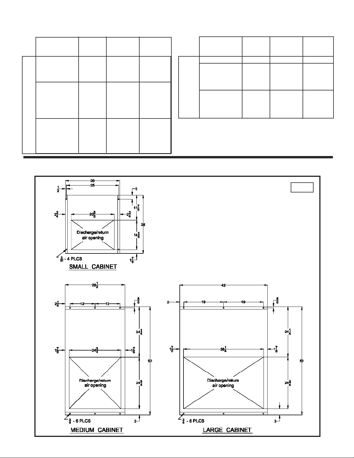
3. Cut a finished opening in the box ceiling to the dimensions shown in the footprint drawings
on page 5. Make sure that the top with the cut-out has the structural integrity to hold the unit.
See table on page 5 for unit weights.
4. Make sure that the surface of the box is clean where the unit gasket will seal around the
opening.
5. Refer to the walk-in box manufacturer's instructions for any procedures that may be necessary
to ensure the integrity of the exposed foam in the panels.
6. Make sure the unit is mounted level - no more than 1/8 inch drop per foot.
7. Place the unit into the provided opening with the evaporator air flow directed toward the door
(See Figure 1 on page 4). Be careful not to damage the grill during installation.
8. Make sure that the condenser air flow is not obstructed.
9. On indoor units, condensate is evaporated by a discharge line loop run through the drain pan
under the compressor, so a drain line is not required.
10. Install the trim pieces around the inside opening.
2

Outdoor Models
Installation is the same as indoor models except as follows:
1. Units must be curb mounted (curb provided by others). To help with curb sizing, see Figure 3 on
page 5 which shows unit footprint dimensions for each cabinet size. (Only medium and large
cabinet units are available for outdoor use.)
2. Make sure curb is level and properly flashed to prevent water leakage into walk-in.
3. Water from rain or snow may get into compressor section of unit. Make sure the curb under this part of
unit is designed with openings so water will not collect inside the curbing.
4. The condensate drain outlet is located on the side of the unit. Field piping may be connected to
the outlet provided it is adequately sloped and heated to prevent freezing, where necessary. The
drain line in the unit is trapped and heated.
5. After connecting electrical power (see Before Unit Start-up), install compressor compartment cover and
weather hood.
Before Unit Start-up
1. Check all mechanical and electrical connections for looseness developed during transit and
tighten as necessary.
2. Adhere to all applicable building and electrical codes when wiring unit.
3. Make sure supply power is correct voltage and phase for unit and is fused properly.
4. If unit is supplied with a power cord, plug unit into power supply.
IMPORTANT:
Do not use extension cords to connect unit to power.
Plug-in to grounded three prong outlet.
Do not remove grounding prong.
Do not use a power adapter.
5. If unit is not supplied with a cord, hard wire to power supply.
After Start-up
1. To protect the compressor (in the event of a brief power interruption), the electronic controller is pro-
grammed for a five minute start-up time delay.
2. See Electronic Controller Operation section to set box temperature (factory settings are 35ºF for coolers
and -10ºF for freezers), and change any control parameters that may have to be changed to fit the appli-
cation. Basic parameters are factory set as follows:
a. Time between defrosts • 6 hours.
b. Defrost termination temperature • 40°F Coolers, 50°F Freezers.
c. Maximum defrost duration before defrost is terminated by time • 50 minutes.
3. Timing for defrosts starts when unit is started, so as set from factory, defrost will occur 6 hours
after start-up and every 6 hours thereafter.
4. Unit defrosting operation should be checked after start-up and periodically thereafter. The
amount and pattern of frosting can vary greatly. Frost build-up is dependent on the temperature
of the room, the type of product being stored, how often new product is brought into the room
and percentage of time the door to the room is open. It may be necessary to periodically change
the number of defrost cycles or adjust the duration of defrost.
3
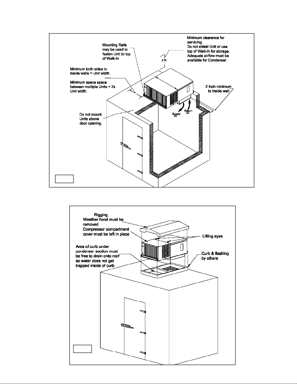
Clearances and Unit Placement
FIG. 1
Outdoor Rigging
FIG. 2
4
Unit Weights
C
O
O
L
E
R
U
N
I
T
S
Model Number
XN026MA**A*
XN029MA**A*
XN037MA**A*
XN050MA**A*
X*050MA**D*
X*068MA**D*
X*076MA**D*
X*106MA**D*
X*106MA**E*
X*134MA**D*
X*134MA**E*
Cabinet
Size
Small
Small
Small
Medium
Medium
Medium
Medium
Large
Large
Large
Large
INDOOR
NET/SHIP
WT. (lbs.)
120 / 185
120 / 185
125 / 190
210 / 305
210 / 305
220 / 315
220 / 315
295 / 420
305 / 430
310 / 435
310 / 435
OUTDOOR
NET/SHIP
WT. (lbs.)
__
__
__
__
220 / 360
230 / 370
230 / 370
310 / 485
320 / 495
325 / 500
325 / 500
F
R
U
E
N
E
I
Z
T
E
S
R
Cabinet Footprints
Model Number
XN018LE44A*
XN024LE44A*
X*024LE44D*
X*031LE44D*
X*043LE44D*
X*051LE44D*
X*051LE44E*
X*068LE44D*
X*068LE44E*
Cabinet
Size
Small
Medium
Medium
Medium
Medium
Large
Large
Large
Large
INDOOR
NET/SHIP
WT. (lbs.)
140 / 200
210 / 305
210 / 305
245 / 340
245 / 340
315 / 445
315 / 445
320 / 450
320 / 450
OUTDOOR
NET/SHIP
WT. (lbs.)
__
__
225 / 365
255 / 400
255 / 400
330 / 510
330 / 510
335 / 515
335 / 515
FIG. 3
Note:
All dimensions are in inches.
5

Maintenance
The following items should be checked every six months. Make sure all power is shut off to unit before performing any maintenance or service.
1. Tighten all electrical connections.
2. Check all wiring and insulators.
3. Check contactor for proper operation.
4. Check all fan motors. Tighten motor mount screws/nuts and fan set screws.
5. Clean the condenser and evaporator coil surfaces.
CAUTION: Avoid contact with sharp edges and coil surfaces. They are potential hazards.
6. Check the operation of the control system. Make sure all safety controls are operating properly.
7. Make sure evaporator is defrosting properly. See item 4 under "After Start-up".
8. Clean the drain pan and drain lines. Check the drain pan and drain line for proper drainage.
On outdoor units make sure the crankcase and drain line heaters, and thermostat are functioning properly.
9.
Sequence of Operation
Coolers
1. When power is supplied to the unit, the compressor, condenser motor(s) and evaporator
motor(s) will run until the box temperature setting is reached.
2. When the box temperature setting is reached, the compressor and condenser motor(s) shut off but
the evaporator motor(s) continue to run. This will provide an off-cycle defrost of the evaporator coil.
3. When the box temperature rises above the set point and the minimum compressor off-time has
elapsed, the compressor and condenser motor(s) will be re-energized.
4. When a defrost is initiated, as set by the electronic controller parameters, the compressor and condenser
motor(s) are shut off until the defrost sensor reaches the termination temperature.
5. Indoor units are not furnished with crankcase heaters, drain line heaters or condenser fan cycling
controls.
Freezers
1. When power is supplied to the unit, the compressor, condenser motor(s) and evaporator motor(s) will run
until the box temperature setting is reached. For outdoor units, depending on the ambient temperature,
condenser fan motor(s) may be off.
2. When the box temperature setting is reached, the compressor and condenser motor(s) shut off
but the evaporator motors continue to run.
3. When the box temperature rises above the set point and the minimum compressor off-time has
elapsed, the compressor and condenser motor(s) will be re-energized.
4. When a defrost is initiated, as set by the electronic controller parameters, the compressor, condenser
motor(s), and evaporator motor(s) are shut off and the defrost heaters are energized.
5. The unit will stay in defrost until the defrost sensor reaches the termination temperature, then
the defrost heaters will de-energized and the unit will go into the drip mode as set on the controller (see
parameter dd).
6

6. After the drip time, the compressor and condenser motor(s) start but the evaporator motor(s) stay off until
defrost sensor reaches the controller parameter settings.
(see parameters F0, F1 & A0)
7. Then the refrigeration cycle is resumed.
ELECTRONIC CONTROLLER OPERATION
The electronic controller controls all of the functions of the APEX system. The following paragraphs explain the
operation of the controller and how to change the settings of the controller parameters. Table 1 shows a listing
of parameteres and settings.
CONTROLLER DISPLAY
During normal operating conditions, the display shows the value measured by the box temperature probe. In
case of an active alarm, the temperature flashes alternately with the alarm code.
LED INDICATIONS ON DISPLAY
Compressor icon illuminated indicates compressor ON
or
Compressor icon flashing indicates compressor in
a time delay status.
Defrost icon illuminated indicates unit in defrost.
Alarm icon illuminated indicates the presence of
an alarm.
7
 Loading...