


www.ruskin.com • 3900 Dr. Greaves Rd. • Kansas City, MO 64030 • (816) 761-7476
INSTALLATION AND OPERATION INSTRUCTIONS
MODEL AMS810 TRANSDUCER
PRODUCT IDENTIFICATION
AMS810 Display Unit OpenAMS810 with Display
MOUNTING
Mount the unit to its mounting surface with four #10 screws through the holes in the mounting feet. The preferred mounting orientation is with the
pressure ports facing down.
Mounting Hole Pattern
Mounting Screws Location
TOOLS & MATERIAL LIST
SCREWDRIVER #10 SCREWS SEALANT FILLED CONNECTORS
DRILL WITH 5/32” BIT WIRE
ALL STATED SPECIFICATIONS ARE SUBJECT TO CHANGE WITHOUT NOTICE OR OBLIGATION. © Ruskin September 2018II-AMS810-918/Replaces II-AMS810/914

OUTPUT TERMINATION
Desired Output Wire connections
4 to 20 mA Red (V+); Black (Return [4 to 20 mA Signal]), White (Not used)
0 to 5 V or 0 to 10 V Red (V+); Black (Ground); White (Output Voltage)
4 to 20 mA is “two wire” operation, the red wire connects to a positive direct current voltage of 7 to 45 VDC, the black wire becomes
the return of the 4 to 20 mA signal and the white wire, while
unused, must be insulated from accidental contact with ground or
any other potential. For 4 to 20 mA signaling only direct current
can be used to power the AMS810.
0 to 5 V or 0 to 10 V is “three wire” operation, the red wire connects
to either 7 to 45 VDC or 7 to 32 VAC (0-5 VDC output) or 13 to 45
VDC or 13 to 32 VAC (0-10 VDC output), the black wire is connect-
ed to ground and the white wire is connected to an analog input of
the controller. Ruskin insulates the white wire in the factory before
shipping to you, please remove the connector and strip the insulation from the white wire for 0-5V or 0-10V operation.
To ensure that all wires are properly terminated, twist the stripped
ends of each circuit together before inserting into the splice terminals. Gently tug on the wire after terminating to make sure of a
good connection. If the wire comes out of the termination repeat
the splice procedure.
DIP SWITCH SETTINGS - INCHES, PASCALS
DIP Switch Settings, Inches W.C. DIP Switch Settings, Pascals
DIP Switch settings for optional, 1-1.0 inch W.C. model DIP Switch settings for optional, 0-250 PA model
PRESSURE RANGE SELECT
To adjust the pressure range, set dip switches 1-4 to the desired pressure range using the label found inside the cover of the unit.
Note: If any of the switches are placed in an undefined combination the
LED will fast blink and the output will be forced to 4mA or zero volts.
OUTPUT RANGE SELECT
To adjust the output range, set dip switches 5 & 6 to the desired output
range using the label found inside the cover of the unit.
Note: If any of the switches are placed in an undefined combination
the LED will fast blink and the output will be forced to 4mA or zero
volts.

AUTO-ZERO SELECT
To auto zero the AMS810 remove the tubing from the pressure
ports (to remove the normal pressure source). Make sure that the
pressure ports are sheltered from any drafts, including the technician’s breath. Ideally the two ports should be connected together
with a short piece of tubing. Turning on switch 7 starts the autozero process. Switches 1 through 6 may be in any allowed configuration. The LED will blink at a fast rate and the output will be forced
to zero (4mA or 0V) while the auto-zero is being performed. When
the LED blinks at a slow rate, turn off switch 7 and reconnect the
pressure source.
Auto-Zero
SWITCH 8
Switch 8 is reserved for factory use, leave in the off posiiton.
TROUBLESHOOTING
PROBLEMS: POSSIBLE SOLUTIONS:
LED does not light - Check power connections for proper power
LED is blinking fast - The unit may be performing an auto-zero. Wait 10 seconds and check again.
(1/2 second on, 1/2 second off)
- The dip switches are in an unsupported configuration, check the dip switch settings, both pressure
and output, and change them to ranges desired
Output stuck (high or low) - Remove pressure from ports and perform auto-zero procedure
Output not tracking pressure properly - Check dip switches for proper pressure range selection
- Check dip switches for proper output range selection
LED OPERATION
LED off No Power
LED Blinking 1/2 sec on, 1/2 sec off Auto-zero or dip switch in undefined configuration
LED on Normal operation
LED Blinking 1/2 sec on, 4 sec off Auto-zero complete
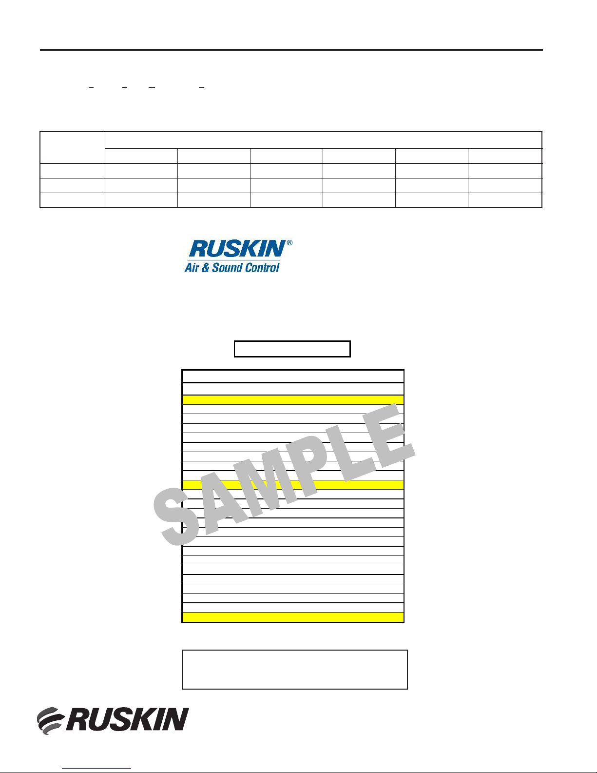
SCALE FORMULAS
SOLD TO: RUSKIN CUSTOMER
C
ONTROL NO: 123456
T
AG: AHU-1
MODEL: AMS050
Ka
3200
Damper Width
17 3/4
1/m 0.5
D
amper Height
17 3/4
A
rea x Ka = 6127.3
N
umber Probes
4
A
rea = 1.9147813
Damper Sections
1
PAMS* CFM
0.005 433
0.01 613
0.02 867
0.03 1,061
0.04 1,225
0.05 1,370
0.06 1,501
0.07 1,621
0.08 1,733
0.09 1,838
0.1 1,938
0.11 2,032
0.12 2,123
0.13 2,209
0.14 2,293
0.15 2,373
0.2 2,740
0.3 3,356
0.4 3,875
0.5 4,333
0.6 4,746
0.7 5,126
0.8 5,480
0.9 5,813
16,127
*PAMS = Pressure Across Measuring Station
0.05 198
3,200
1,431
1,753
2,024
2,479
3,036
2,263
1,154
1,197
2,677
2,862
1,239
640
716
1,012
1,109
784
847
905
960
1,061
10.00
6.00
7.00
8.00
9.00
2.00
3.00
4.00
5.00
1.20
1.30
1.40
1.50
0.80
0.90
1.00
1.10
0.40
0.50
0.60
0.70
3200.10
0.20
0.30
453
554
CFM = (AREA * Ka) * PAMS
(1/m)
Actual Damper Size (inches)
VOLTS FPM
The AMS810 is factory configured for 0-1” W.G. with an output signal of 0-10 VDC. Each Air Measurement Station is shipped with a
PAMS chart (Pressure Across Measurement Station) indicating the
output signal proportional to CFM. Adjusting the dip switch to a different pressure range or analog output signal varies the formulas
used to calculate CFM.
Voltage Range
In order to convert the analog output signal from the pressure transducer to differential pressure use the multiplier in Table 1 for the combination selected. Then use the “Area x Ka” and “1/m” values from the
PAMS chart to calculate CFM with the following formula:
PAMS = Scale Formula x VDC
CFM = (Area x Ka) x (PAMS)
(1/m)
Pressure Range
.10” W.G. .25” W.G. .5” W.G. .75” W.G. 1.0” W.G. 2.5” W.G.
0-10 VDC .01x(VDC) .025x(VDC) .05x(VDC) .075x(VDC) 0.1x(VDC) .25x(VDC)
0-5 VDC .02x(VDC) .05x(VDC) .1x(VDC) .15x(VDC) .2x(VDC) .5x(VDC)
4-20 mA .0063x(mA) - .025 .0156x(mA) - .0625 .0312x(mA) - .125 .0468(mA) - .1875 .0625x(mA) - .25 .1563x(mA) - .625
Table 1: Scale Formulas
NOTE: CFM corrected to 70°F. & 1000 FT elevation for other
elevations add 2% per 1000 ft. increase and 1% per 10°F
increase in temp.
3900 Dr. Greaves Rd.
Kansas City, MO 64030
(816) 761-7476
FAX (816) 765-8955
www.ruskin.com
 Loading...