

Page 1
© All rights reserved to Ruptela UAB
User Manual
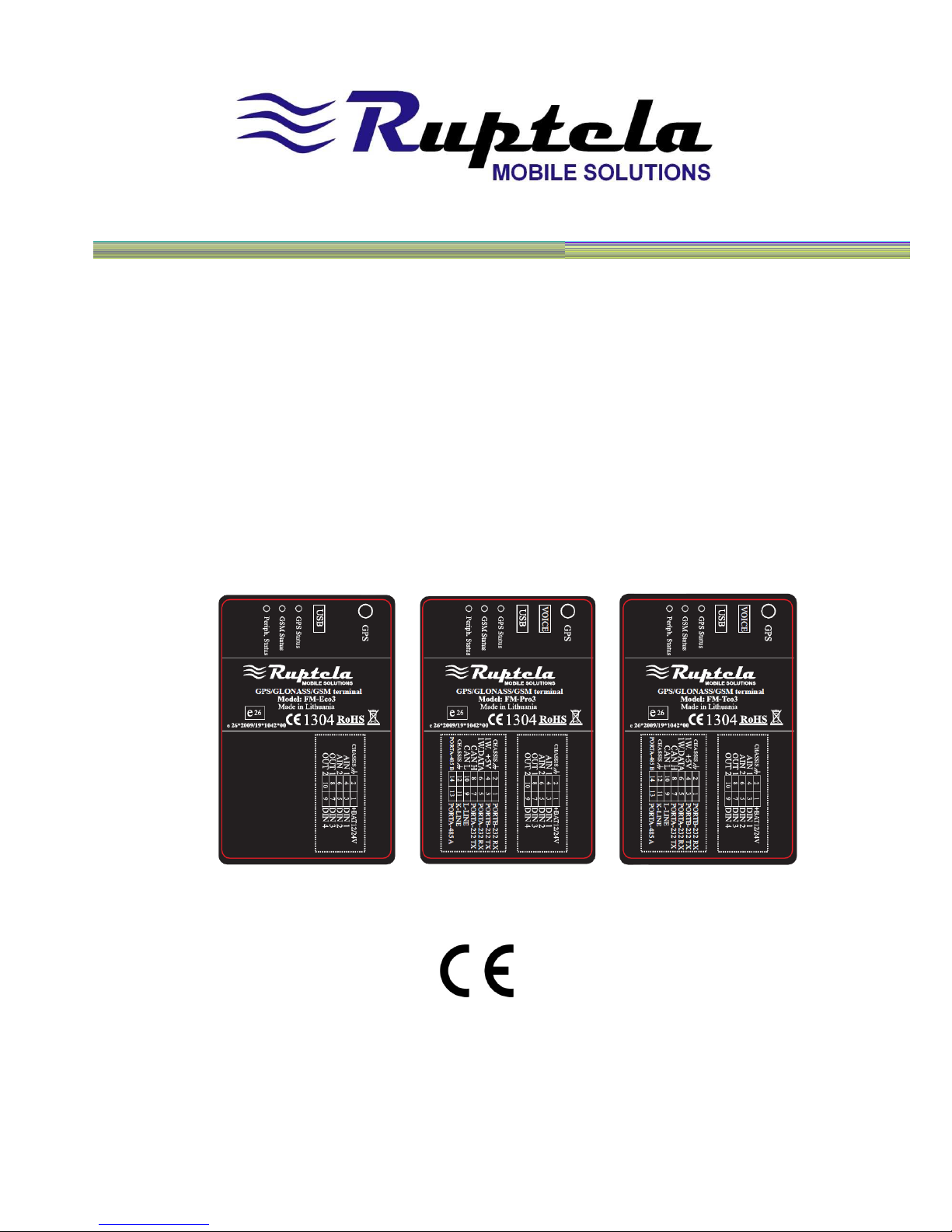
FM
ECO3 / PRO3 / TCO3 /
Version 7. Last update 2013-08-27
Page 2

© All rights reserved to Ruptela UAB
P a g e |
2
Content
1. INTRODUCTION – P
AGE
4-6
1.1.
ACRONYMS AND TERMS USED IN DOCUMENT – P
AGE
4
1.2.
LEGAL NOTICE – P
AGE
4
1.3.
SAFETY REQUIREMENTS – P
AGE
5-6
2.
FM-PRO3 – P
AGE
7-16
2.1.
BASIC DESCRIPTION – P
AGE
7
2.2.
PACKAGE CONTENTS – P
AGE
8
2.3.
ADDITIONAL ACCESSORIES – P
AGE
8
2.4.
BASIC CHARACTERISTICS– P
AGE
9
2.5.
TECHNICAL FEATURES – P
AGE
10
2.6.
FM-PRO3 DIMENSIONS – P
AGE
11
2.7.
LED STATUSES – P
AGE
12-13
2.8.
PINOUT CONNECTION, USB – P
AGE
14-15
2.9.
SPECIAL FEATURES – P
AGE
15
2.10.
QUALIFICATION AND CERTIFICATION – P
AGE
16
3.
FM-ECO3 – P
AGE
17-2 4
3.1.
BASIC DESCRIPTION – P
AGE
17
3.2.
PACKAGE CONTENTS – P
AGE
18
3.3.
ADDITIONAL ACCESSORIES – P
AGE
18
3.4.
BASIC CHARACTERISTICS – P
AGE
19
3.5.
TECHNICAL FEATURES – P
AGE
20
3.6.
FM-ECO3 DIMENSIONS – P
AGE
21
3.7.
LED STATUSES – P
AGE
22
3.8.
PINOUT CONNECTION, USB – P
AGE
23-24
3.9.
SPECIAL FEATURES – P
AGE
24
FM Manual
Page 3

© All rights reserved to Ruptela UAB
P a g e |
3
3.10.
QUALIFICATION AND CERTIFICATION – P
AGE
24
4.
FM-TCO3 – P
AGE
25-3 4
4.1.
BASIC DESCRIPTION – P
AGE
25
4.2.
PACKAGE CONTENTS – P
AGE
26
4.3.
ADDITIONAL ACCESSORIES – P
AGE
26
4.4.
BASIC CHARACTERISTICS – P
AGE
27
4.5.
TECHNICAL FEATURES – P
AGE
28
4.6.
FM-TCO3 DIMENSIONS – P
AGE
29
4.7.
LED STATUSES – P
AGE
30-31
4.8.
PINOUT CONNECTION, USB – P
AGE
32-33
4.9.
SPECIAL FEATURES – P
AGE
33-34
4.10.
QUALIFICATION AND CERTIFICATION – P
AGE
34
5.
INST ALLATION AND CONFIGURATION INST RUCTIONS – P
AGE
35-
5.1.
MODULE INSTALLATION – P
AGE
35-36
5.2.DEVICE
CONNECTION TO A PERSONAL COMPUTER – P
AGE
37
5.2.1.SYSTEM
REQUIREMENTS – P
AGE
37
5.2.2.
PREPARATION FOR CONNECTION – P
AGE
37
5.2.3.
DRIVER INSTALLATION – P
AGE
38-42
5.3.
CONFIGURATOR – P
AGE
42
5.3.1.
INTERFACING TO COM PORT – P
AGE
42-44
5.3.2.
GLOBAL PARAMETER CONFIGURATION – P
AGE
44-46
5.3.3.
PROFILE CONFIGURATION – P
AGE
47-55
5.3.4.
SAVING AND LOADING CONFIGURATION – P
AGE
55-57
5.3.5.
CONFIGURATION EXCHANGE WITH A DEVICE – P
AGE
57
5.4.FIRMWARE
UPDATE – P
AGE
57-58
5.5.
APPENDIX – IO LIST – P
AGE
59-67
FM Manual
Page 4

© All rights reserved to Ruptela UAB
P a g e |
4
1. INTRODUCTION
1.1. ACRONYMS AND TERMS USED IN DOCUMENT
• PC – Personal Computer;
• FM Terminal – FM-Pro3 / FM-Tco3 / FM-Eco3 series device;
• GPRS – General Packet Radio Service;
• GPS – Global Positioning System;
• GSM – Global System for Mobile Communications;
• GLONASS – GLObal NAvigation Satellite System;
• SMS – Short Message Service;
• AC/DC – Alternating Current/Direct Current;
• Record – Data which is stored in FM 3 memory. Data contains GPS and I/O Information;
• FMS – An optional standard interface of different truck manufacturers;
• Simplified RS232 – connection standard between different pieces of equipment. Simplified
RS232 has only Rx and Tx lines;
• RS485 – connection standard between different (multiple) pieces of equipment (physically
connected with Port A, where Simplified RS232 is placed). We can configure a device to use
RS485 or RS232 as Port A;
• LED – Light Emitting Diode;
• CAN-bus – FMS standard interface;
• I/O – Inputs / Outputs;
• OBD - On-Board Diagnostics socket;
•K_Line, L_Line – PINs of OBD interface.
1.2. LEGAL NOTICE
Copyright © 2012 Ruptela. All rights reserved. Reproduction, transfer, distribution or storage of
parts or all of the contents in this document in any form without the prior written permission of
Ruptela is prohibited. Other products and company names mentioned in this document are
trademarks or trade names of their respective owners.
FM Manual
Page 5
© All rights reserved to Ruptela UAB
P a g e |
5
1.3. SAFETY REQUIREMENTS
All the associated (additional) equipment as PC, batteries, sensors and
others, shall meet the requirements of standard EN60950-1.
Do not disassemble the terminal. If the enclosure of the terminal is
damaged, or the insulation of wires is damaged, first of all unplug the
10 pins connector from the terminal carefully
.
All of the wireless data transferring equipment produces interference
that may affect other devices which are placed nearby.
The terminal can be installed or dismounted only by qualified
personnel!
The terminal must be firmly fastened in the predefined location.
Predefined location is explained in the mounting instructions.
The programming must be performed using a 2nd safety class of PCs
(with autonomic power supply).
Be sure that the terminal is installed in a place where it cannot be
reached by water drops and humidity.
Caution!!!! There is a risk of explosion if the battery is replaced by an
incorrect type. Dispose used batteries according to the instructions.
FM Manual
Page 6
© All rights reserved to Ruptela UAB
P a g e |
6
Any installation and/or handling during a lightning storm is prohibited.
Use cables provided with FM device.
Ruptela is not responsible for any harm caused by using wrong cables
for PC <-> FM Terminal connection.
Attention! Do not connect the wires marked (+ battery) wrongly and
(chassis) to battery poles. If poles are mixed, the device will break.
To disconnect the device from the power supply, you need to
disconnect 10 PINs plug and connect to internal battery.
This chapter contains information on how to operate with the FM terminal safely. By following
these requirements and recommendations, you will avoid dangerous situations. You must read
these instructions carefully and follow them strictly before operating the device! The terminal is
supplied from a car battery with these ratings: 12/24V
1A/500mA. The allowed voltage range
for the battery is: 10…32V DC.
To avoid mechanical damage, it is advised to transport the FM terminal in an impact-proof
package.
Before connecting the wires with 14 PINs plug to the vehicle, ensure that 10 PINs plug is
disconnected from the terminal. Be sure that cross-sectional area of wires mounting is at least
0.75 mm2.
To dismount terminal correctly from the vehicle, first of all disconnect 10 PINs plug and only then
other plugs or interfaces can be disconnected.
Always connect 14 PINs plug before connecting 10 PINs plug.
The terminal is intended to be installed in a restricted access location, which is not accessible for
the operator. The terminal is not intended to be used for boats.
FM Manual
Page 7
© All rights reserved to Ruptela UAB
P a g e |
7
2. FM-PRO3
2.1. BASIC DESCRIPTION
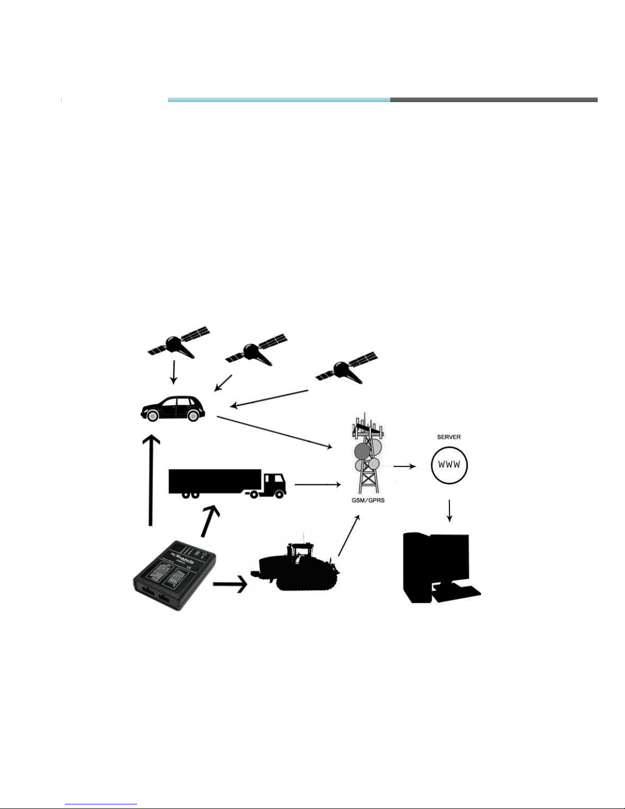
FM-Pro3 is a terminal with GPS/GLONASS / GSM connectivity, which is able to determine the
object’s coordinates and transfer them via the GSM network. This terminal is perfectly suitable for
applications where location acquirement of remote objects is needed. It is important to mention
that FM-Pro3 has additional inputs and outputs, which let control and monitor other remote
objects. 1-Wire® interface (for Dallas Digital Thermometer or I-Button Reader) and CAN-bus
interface are integrated (for data acquisition of trucks FMS data interface). It also has 2 simplified
RS232 ports and one RS485 to connect additional equipment such as Personal Navigation
Device, digital fuel level sensor or other (special firmware is required for this).
Figure1. Example of application of GPS/GLONASS/GSM terminal FM-Pro3 for controlling and monitoring of remote
objects.
FM-Pro3
Page 8
© All rights reserved to Ruptela UAB
P a g e |
8
2.2. BASIC DESCRIPTION
Figure2. FM Pro3 device, power and I/O cables and GPS/GLONASS antenna.
The FM-Pro3 device is supplied to the customer in a cardboard box containing all the
equipment that is necessary for operation. The package contains:
• The FM-Pro3 device;
• 10 PIN plug with wires for power supply and I/O connection;
• Magnetic GPS/GLONASS antenna with sticker;
• 14 PIN plug with wires for CAN-bus, 1-Wire, 2 simplified RS232, RS485 and K_line, L_line
connection.
2.3. ADDITIONAL ACCESSORIES
There are a few standard accessories available for FM-Pro3 that are not included in the
package:
• Analog Temperature sensor;
• 1-Wire Digital Temperature Sensor DS18B20 / DS18S20;
• I-Button.
Note: the manufacturer does not supply a SIM card in the package, which is necessary for
connection to the GSM network! SIM card can be obtained from your local GSM service provider!
SIM card can work with the Terminal only when all SIM card security codes are disabled!
If any of the components are not in the package, please contact the manufacturer’s
representative or the vendor (
www.ruptela.com).
FM-Pro3
Page 9
© All rights reserved to Ruptela UAB
P a g e |
9
2.4. BASIC CHARACTERISTICS
Inputs / Outputs:
IO1 – 10 pin (2x5 plug):
IO2 – 14 pin (2x7 plug):
Paired connection scheme:
Other Inputs / Outputs are not paired. Also two spare Chassis pins can be paired with any I/O,
they are only for easier mounting.
FM-Pro3
Page 10
© All rights reserved to Ruptela UAB
P a g e |
10
2.5. TECHNICAL FEATURES
Power supply
External Battery Ratings:
+12/24V 1A/500mA
Internal battery Ratings:
Li-Po 3.7V 680 mAh (up
to 3 hours)
GPS Ublox module (with
external GPS/GLONASS
antenna)
GPRS/GSM Simcom module (with
internal GSM antenna)
Accelerometer LIS3DH accelerometer
Fuses External fuse (mounted
into +BAT wire):
F 2AL
Internal fuse (mounted
into internal battery
module):
SMD 2A
LED’s GPS fix LED,
GSM LED,
Peripheral LED,
All LED’s are green.
Mini USB Mini USB socket
SIM SIM card holder with lock
Dimensions 111.25 x 75 x 25.2 mm
10 pin plug For ex. Tyco multi-lock
4-794619-0 socket
Weight 140g
14 pin plug For ex. Tyco multi-lock
4-794619-4 socket
Temperatures Operational temp.:
-35°C ... +55°C
Storage temp.:
-40°C ... +65°C
Housing /
Material
UL94-HB Plastic case
2x Simplified
RS232 ports
PORTA Rx, Tx
PORTB Rx, Tx
TRRS
connector
3,5 mm TRRS connector
for handle speaker and
microphone
RS485 port PORTA – 485
Micro SD Micro SD card holder
FM-Pro3
Page 11
© All rights reserved to Ruptela UAB
P a g e |
11
2.6. FM PRO 3 DIMENSIONS
FM-Pro3
Page 12
© All rights reserved to Ruptela UAB
P a g e |
12
2.7. LED STATUSES
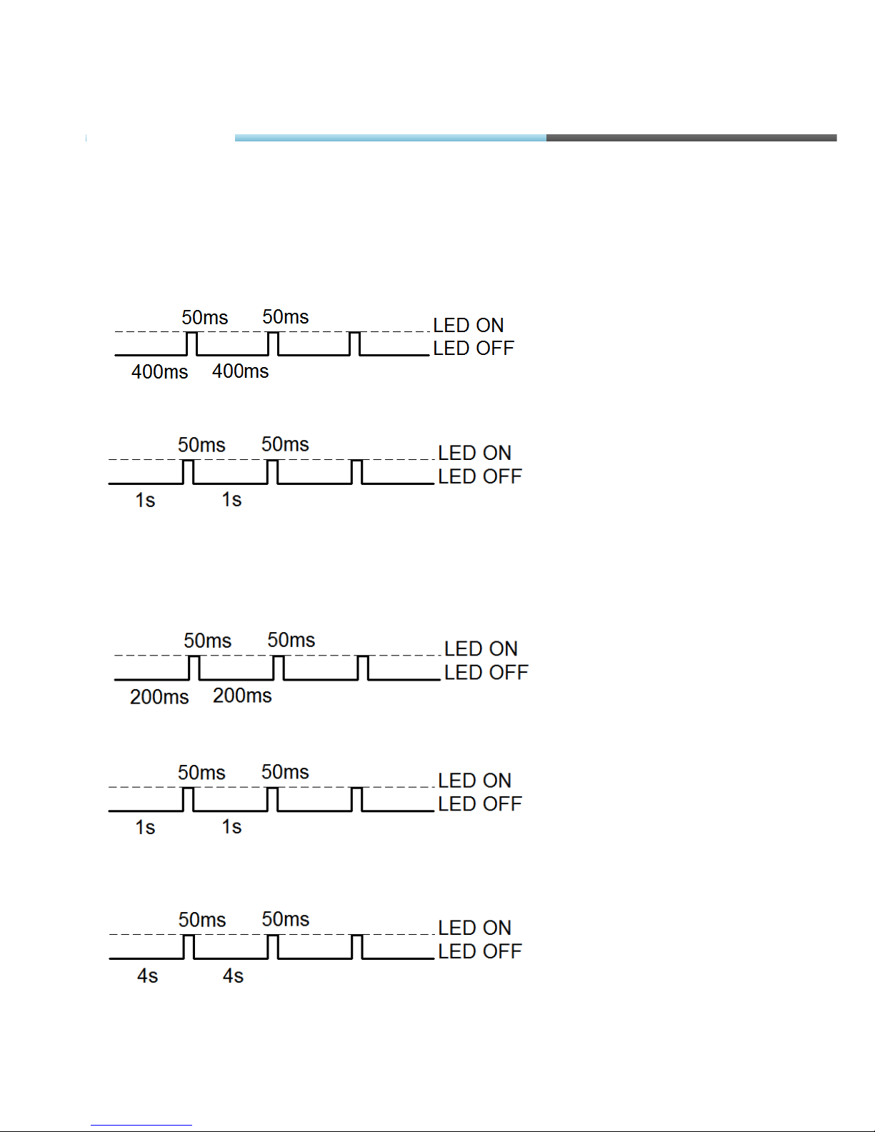
GPS LED
When GPS/GLONASS signal is not received or GPS/GLONASS signal is not accurate, the GPS
LED is blinking as follows:
When accurate GPS/GLONASS signal is received, the GPS LED is blinking as follows:
GSM LED
When GSM signal is not received, GSM LED is blinking as follows:
When device has a good GSM signal, but no GPRS, LED is blinking as follows:
When device has good GSM signal and it is connected to GPRS, then LED is blinking as
follows:
FM-Pro3
Page 13
© All rights reserved to Ruptela UAB
P a g e
|
13
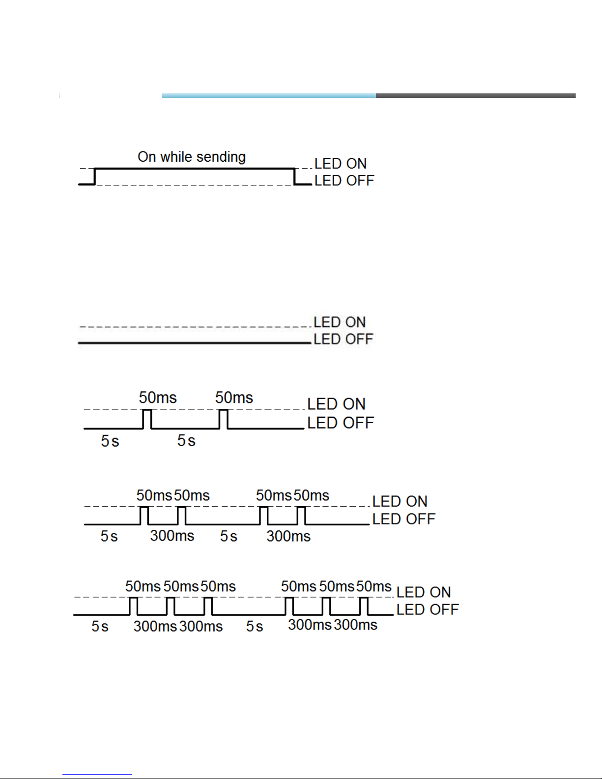
When the FM-Pro3 terminal has GSM signal and it is sending data via GPRS, LED is blinking:
Peripheral LED
To the FM-Pro3 terminal can be attached up to three peripheral interfaces. So there are 3
different types of blinking when one or other peripheral is connected.
When there is no peripheral attached, LED will not blink at all:
When there is 1 out of 3 peripheral interfaces connected, the peripheral LED is blinking:
When there are 2 out of 3 peripheral interfaces connected, peripheral LED is blinking:
When there are 3 out of 3 peripheral interfaces connected, Peripheral LED is blinking:
FM-Pro3
Page 14
© All rights reserved to Ruptela UAB
P a g e |
14
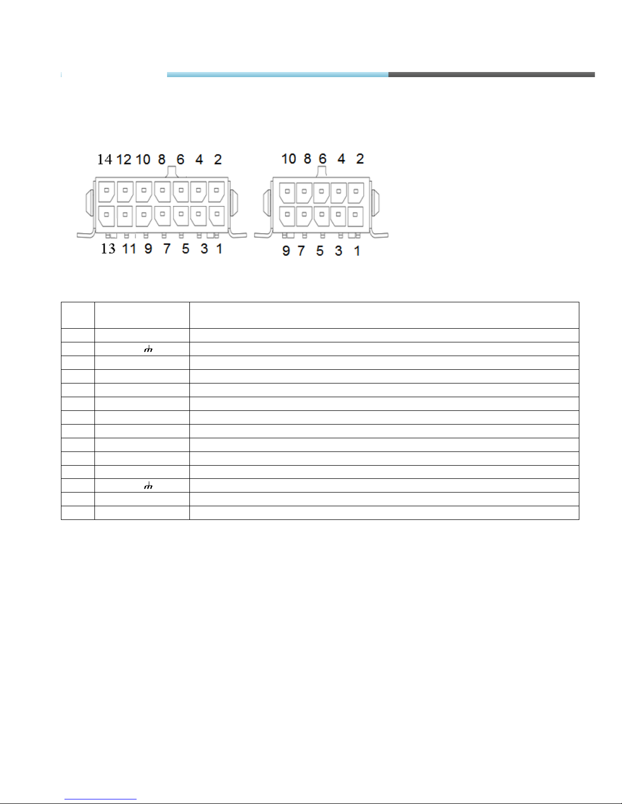
2.8. PINOUT CONNECTION, USB
FM-Pro3 standard plugs, 14 and 10 pins.
Standard FM-Pro3 14 PINs plug description:
Pin
No.
Pin name
Description
1. PortB RX Port B receive signal
2. Chassis The frame or chassis of a car.
3. PortB TX Port B transit signal
4. OUT +5V +5V output for Dallas 1-Wire® devices (max 20 mA)
5. PortA RX Port A receive signal
6. Data Data channel for Dallas 1-Wire® devices
7. PortA TX Port A transit signal
8. CAN H SAE J1939 CAN interface High channel
9. L_Line SAE J1939 CAN interface L_Line channel, diagnostics
10. CAN L SAE J1939 CAN interface Low channel
11. K_Line SAE J1939 CAN interface K_Line channel, diagnostics
12. Chassis The frame or chassis of a car
13. PORTA-485A RS-485 differential signaling line A
14. PORTA-485B RS-485 differential signaling line B
TRRS connector is used for connecting speaker and microphone to FM device. Communication is
half-dulpex, so you can’t listen and speak at the same time (you have to use a switch). To initialize
a conversation - you need to call from your phone to SIM card number, which is inside the device.
Device will automatically answer this call. More information about TRRS is stored in TRRS
connector specification.
FM-Pro3
Page 15
© All rights reserved to Ruptela UAB
P a g e |
15
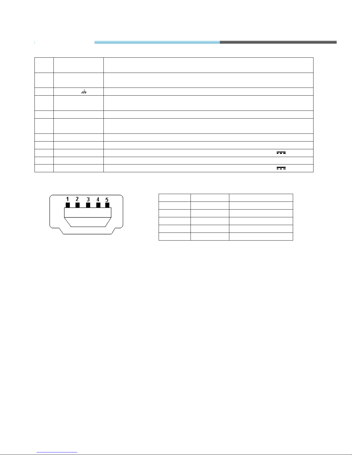
Standard FM-Pro3 10 PINs plug description:
Pin
No.
Pin name
Description
1. +BAT 12/24V Battery rated voltage: 12/24V.
Allowed battery voltage range
: 10...32V
2. Chassis The frame or chassis of a car
3. DIN 1 Digital input, channel 1(It can be also used as a pulse counter).
Threshold 4V
4. AIN 1 Analog input, channel 1. Input range: 0 – 30V
5. DIN 2 Digital input, channel 2(It can be also used as a pulse counter).
Threshold 4V
6. AIN 2 Analog input, channel 2. Input range: 0 – 30V
7. DIN 3 Digital input, channel 3. Threshold 4V
8. OUT 1 Digital output. Channel 1. Open collector output. Max. 32V 250 mA
9. DIN 4 Digital input, channel 4. Threshold 4V
10. OUT 2 Digital output. Channel 2. Open collector output. Max. 32V 250 mA
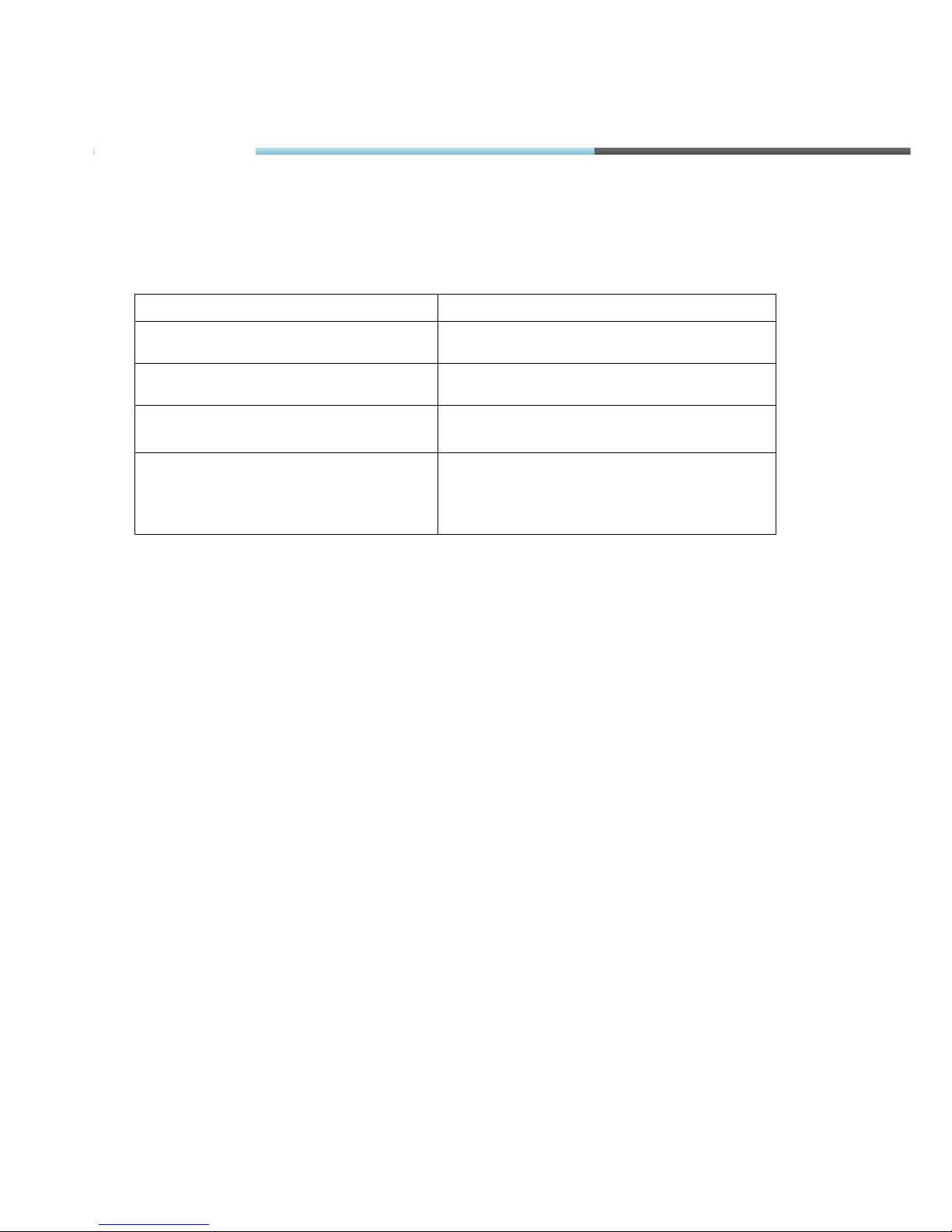
USB
2.9. SPECIAL FEATURES
• Any element event triggers (external sensor, input, speed, temperature, etc.);
• Smart profile switching (GSM operator or any element depended);
• Highly configurable data acquisition and sending;
• Real-time process monitoring;
• Authorized number list for remote access;
• Firmware update via GPRS or Mini USB port;
• Configuration update via GPRS, SMS or Mini USB port;
• TCP/IP or UDP/IP protocol support;
• 16 000 record storing (without micro SD card);
• Up to 32 GB micro SD card as Flash memory extension;
• Ability to connect speaker/ microphone (with switching capability) through 3,5 mm TRRS
connector.
Pin No.
Pin name
Description
1. VBUS Power
2. D- Data -
3. D+ Data +
4. ID NC
5. GND Ground
FM-Pro3
Page 16
© All rights reserved to Ruptela UAB
P a g e |
16
2.10. QUALIFICATION AND CERTIFICATION
The FM-Pro3 terminal complies the essential requirements detailed in the following Articles of
the Directive:
Essential Requirements
Conformed Specifications / Standards
Safety
R&TTE, Article 3.1(a)
EN 60950-1:2006+A11:2009
EMC
R&TTE, Article 3.1(b)
EN 301 489-1 V1.6.1
EN 301 489-7 V1.3.1
Radio Spectrum
R&TTE, Article 3.2
EN 301 511 (v9.0.2)
Environmental testing. Part 2-64.
Tests – Test Fh: Vibration,
broadband random and guidance
(IEC 60068-2-64:2008)
LST EN 60068-2-64:2008
FM-Pro3
Page 17
© All rights reserved to Ruptela UAB
P a g e |
17
3. FM-ECO3
3.1. BASIC DESCRIPTION
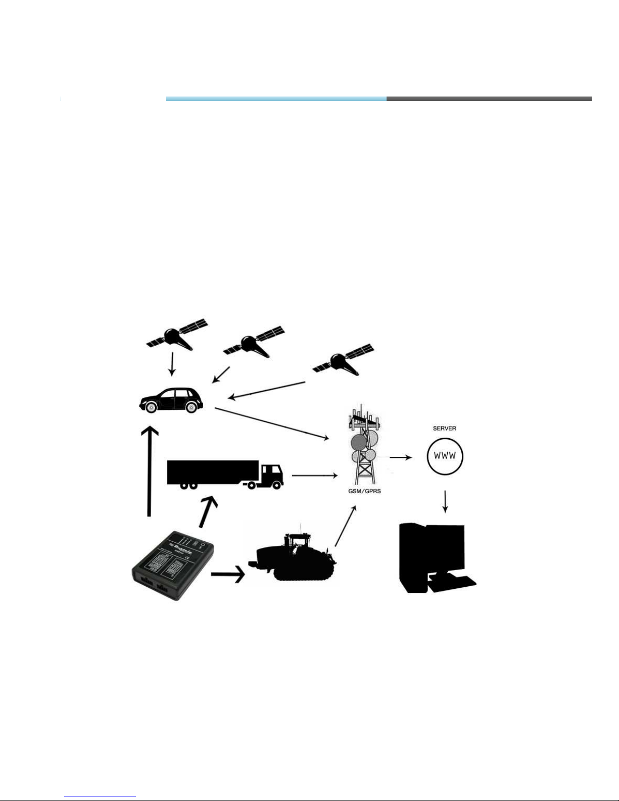
FM-Eco3 is a terminal with GPS/GLONASS / GSM connectivity, which is able to determine the
object’s
coordinates and transfer them via the GSM network. This terminal is perfectly suitable for
applications where location acquirement of remote objects is needed. It is important to mention
that FM-Eco3 has additional inputs and outputs, which let control and monitor other
remote objects.
Figure1. Example of application of GPS/GLONASS/GSM terminal FM-Eco3 for controlling and monitoring of remote
objects.
FM-Eco3
Page 18
© All rights reserved to Ruptela UAB
P a g e |
18
3.2. PACKAGE CONTENTS
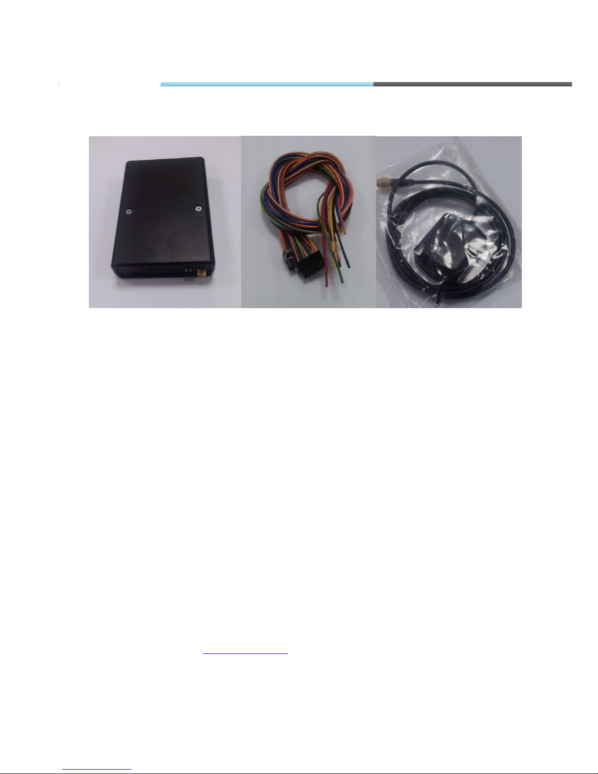
Figure2. FM-Eco3 device, power and I/O cables and GPS/GLONASS antenna
.
The FM-Eco3 terminal is supplied to the customer in a cardboard box containing all the
equipment which is necessary for operation.
The package contains:
• The FM-Eco3 Terminal.
• 10 PIN plug with wires for power supply and I/O connection
• Magnetic GPS/GLONASS antenna with sticker.
3.3. ADDITIONAL ACCESSORIES
There are a few standard accessories available for FM-Eco3 that are not included in the
package:
• Analog Temperature sensor
Note: the manufacturer does not supply a SIM card in the package, which is necessary for
connection to the GSM network! SIM card can be obtained from your local GSM service provider!
SIM card can work with the terminal only when all SIM card security codes are disabled!
If any of the components are not in the package, please contact the manufacturer’s
representative or the vendor (
www.ruptela.com).
FM-Eco3
Page 19
© All rights reserved to Ruptela UAB
P a g e |
19
3.4. BASIC CHARACTERISTICS
Inputs / Outputs:
IO1 – 10 pin (2x5 plug):
Paired connection scheme:
Other Inputs / Outputs are not paired.
FM-Eco3
Page 20

© All rights reserved to Ruptela UAB
P a g e |
20
3.5. TECHNICAL FEATURES
Power supply
External Battery Ratings:
+12/24V 1A/500mA
GPS Ublox module (with
external GPS/GLONASS
antenna)
GPRS/GSM Simcom module (with
internal GSM antenna)
Accelerometer LIS3DH accelerometer
Fuses External fuse (mounted
into +BAT wire):
F 2AL
LED’s GPS fix LED,
GSM LED,
All LED’s are green.
Mini USB Mini USB socket
SIM SIM card holder with lock
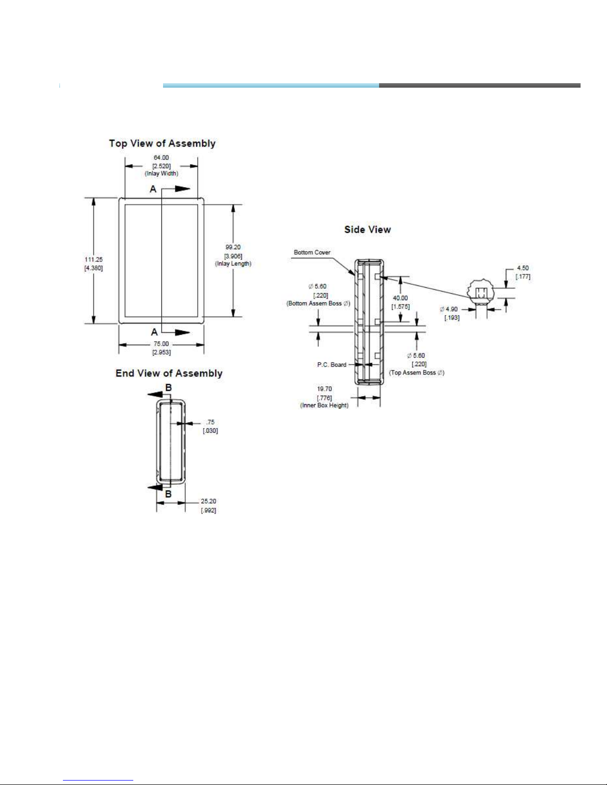
Dimensions 111.25 x 75 x 25.2 mm
10 pin plug Tyco multi-lock 4-
794619-0 socket
Weight 110g
Housing /
Material
UL94-HB Plastic case
Temperatures Operational temp.:
-35°C ... +55°C
Storage temp.:
-40°C ... +65°C
FM-Eco3
Page 21
© All rights reserved to Ruptela UAB
P a g e |
21
3.6. FM-ECO3 DIMENSIONS
FM-Eco3
Page 22
© All rights reserved to Ruptela UAB
P a g e |
22
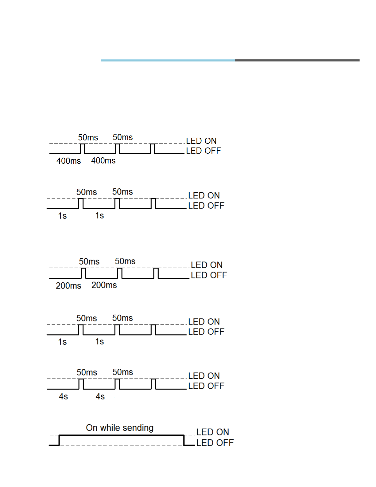
3.7. LED STATUSES
GPS LED
When GPS/GLONASS signal is not received or GPS/GLONASS signal is not accurate, the GPS
LED is blinking as follows:
When accurate GPS/GLONASS signal is received, the GPS LED is blinking as follows:
GSM LED
When GSM signal is not received, GSM LED is blinking:
When device has good GSM signal, but no GPRS, LED is blinking:
When device has good GSM signal and it is connected to GPRS, then LED is blinking:
When the FM-Eco3 terminal has GSM signal and it is sending data via GPRS, LED is blinking:
FM-Eco3
Page 23
© All rights reserved to Ruptela UAB
P a g e |
23
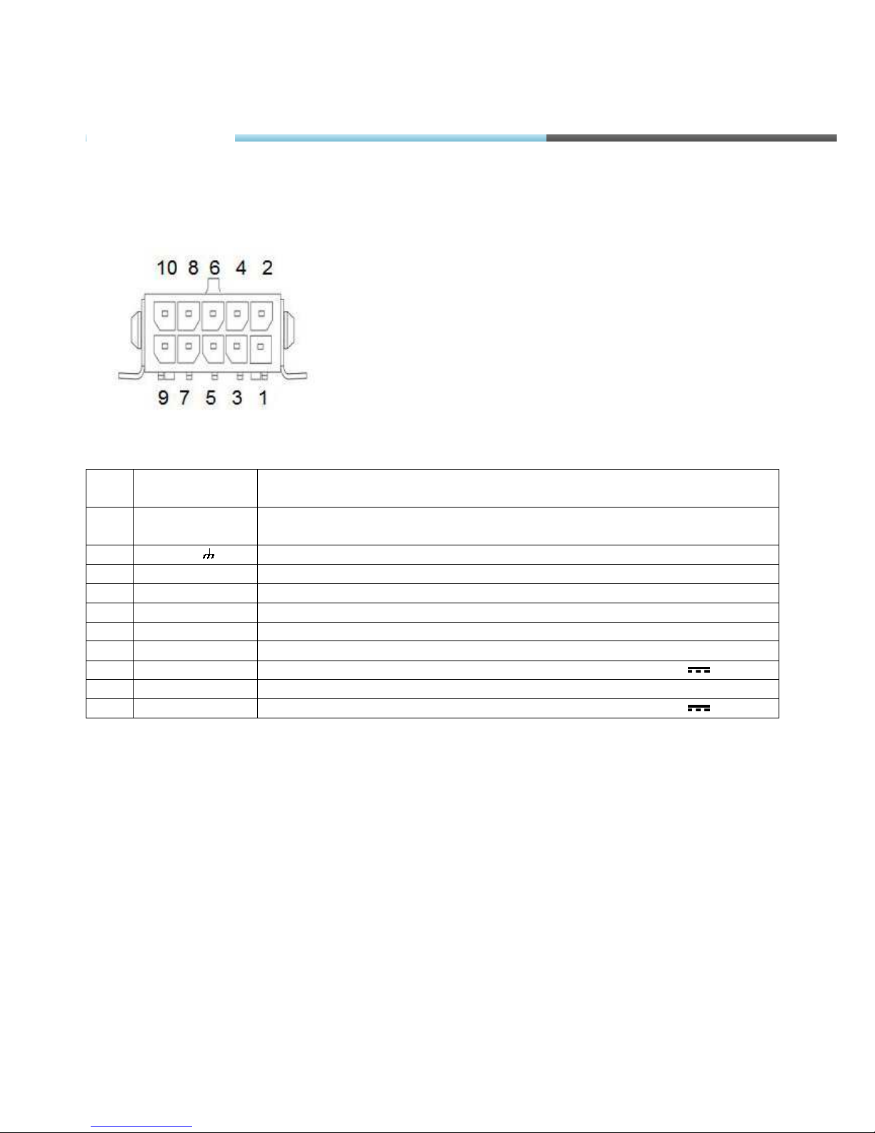
3.8. PINOUT CONNECTION, USB
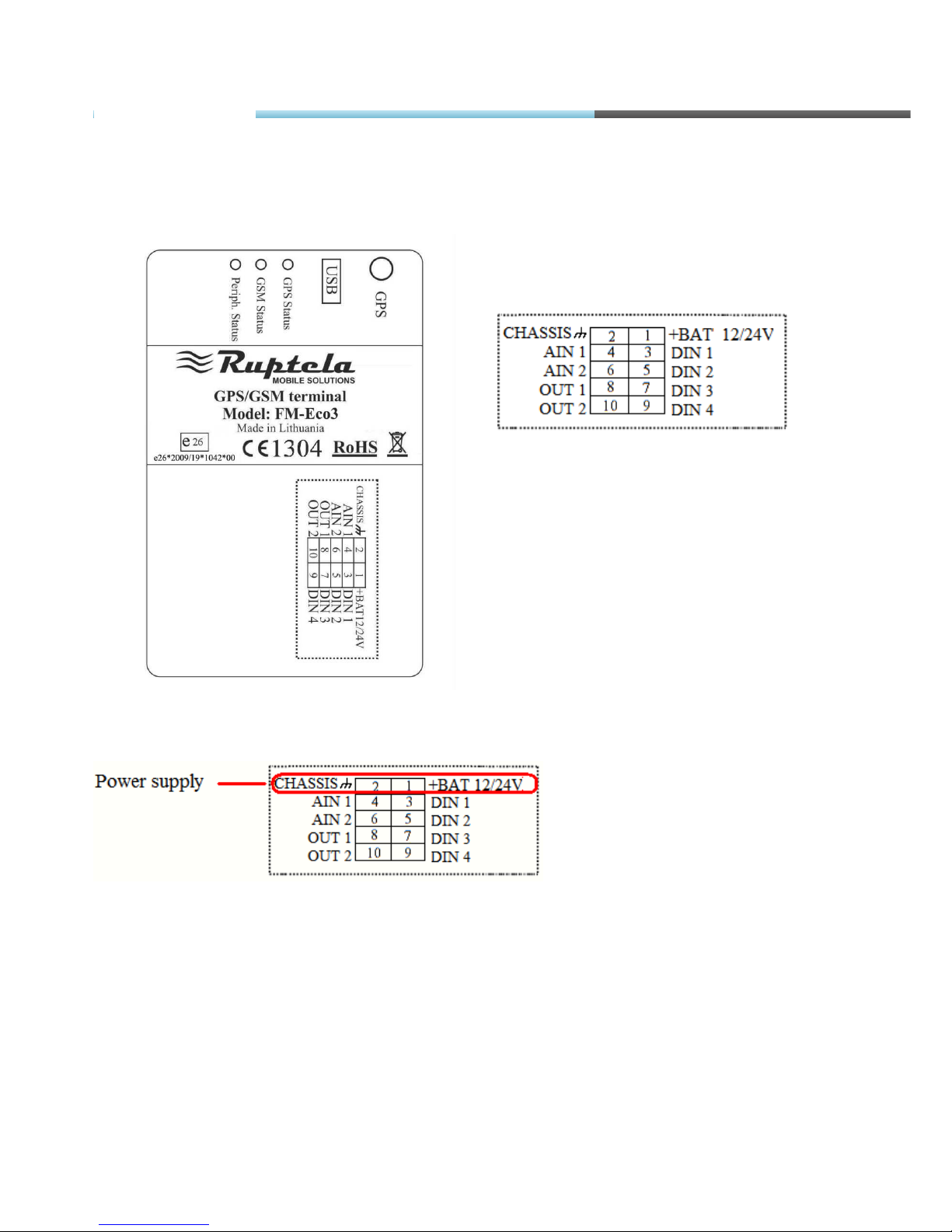
FM-Eco3 standard 10 PINs plug.
Standard FM-Eco3 10 PINs plug description:
Pin
No.
Pin name
Description
1. +BAT 12/24V Battery rated voltage: 12/24V.
Allowed battery voltagerange
: 10...32V
2. Chassis The frame or chassis of a car
3. DIN 1 Digital input, channel 1. Threshold 4V
4. AIN 1 Analog input, channel 1. Input range: 0 – 30V
5. DIN 2 Digital input, channel 2. Threshold 4V
6. AIN 2 Analog input, channel 2. Input range: 0 – 30V
7. DIN 3 Digital input, channel 3. Threshold 4V
8. OUT 1 Digital output. Channel 1. Open collector output. Max. 32V 250 mA
9. DIN 4 Digital input, channel 4. Threshold 4V
10. OUT 2 Digital output. Channel 2. Open collector output. Max. 32V 250 mA
FM-Eco3
Page 24
© All rights reserved to Ruptela UAB
P a g e |
24
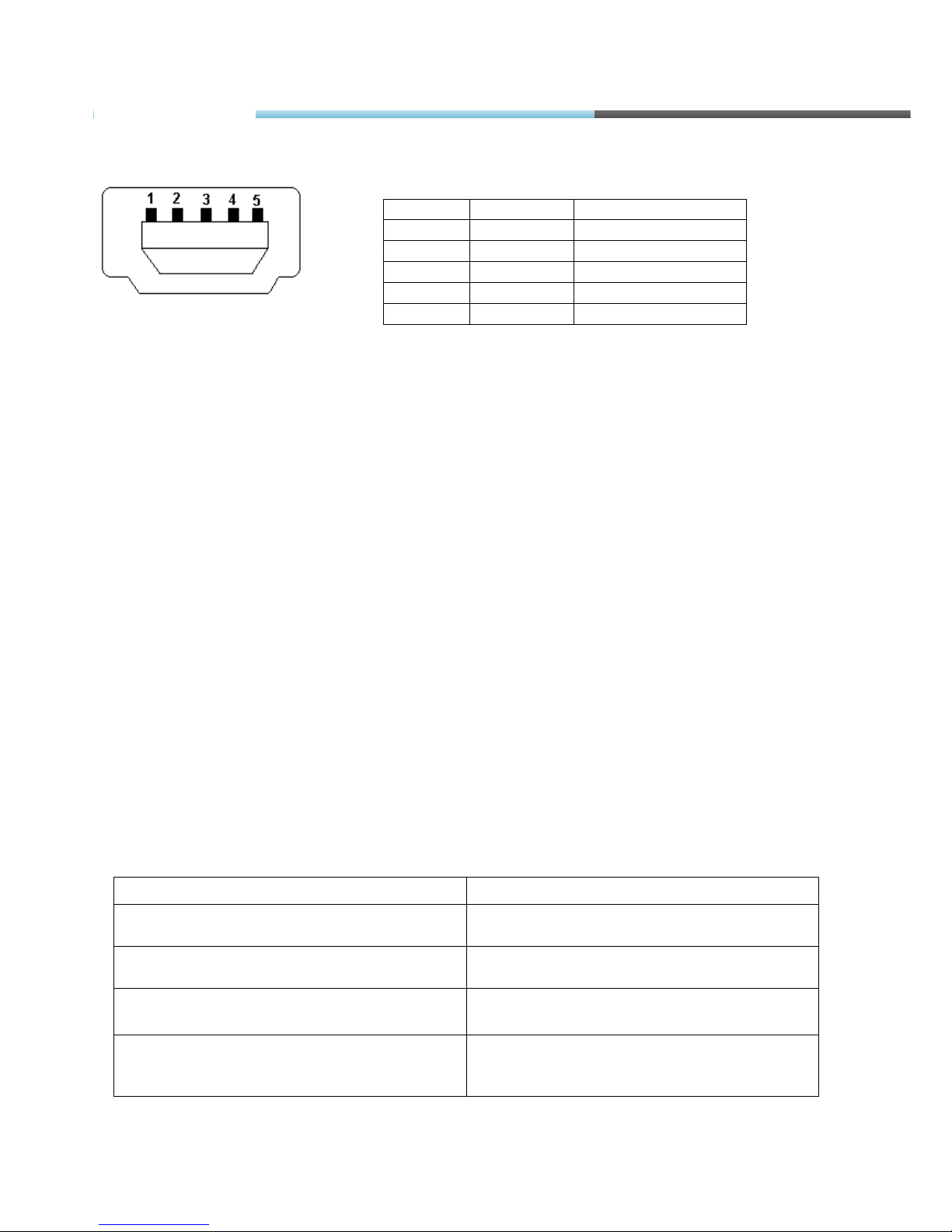
USB
Pin No.
Pin name
Description
1. VBUS Power
2. D- Data -
3. D+ Data +
4. ID NC
5. GND Ground
3.9. SPECIAL FEATURES
• Any element event triggers (external sensor, input, speed, temperature, etc.);
• Smart profile switching (GSM operator or any element depended);
• Highly configurable data acquisition and sending;
• Real-time process monitoring;
• Authorized number list for remote access;
• Firmware update via GPRS or Mini USB port;
• Configuration update via GPRS, SMS or Mini USB port;
• TCP/IP or UDP/IP protocol support;
• 16 000 record storing.
3.10. QUALIFICATION AND CERTIFICATION
The FM-Eco3 terminal complies the essential requirements detailed in the following Articles of
the Directive:
Essential Requirements
Conformed Specifications / Standards
Safety
R&TTE, Article 3.1(a)
EN 60950-1:2006+A11:2009
EMC
R&TTE, Article 3.1(b)
EN 301 489-1 V1.6.1
EN 301 489-7 V1.3.1
Radio Spectrum
R&TTE, Article 3.2
EN 301 511 (v9.0.2)
Environmental testing. Part 2-64. Tests –
Test Fh: Vibration, broadband random and
guidance (IEC 60068-2-64:2008)
LST EN 60068-2-64:2008
FM-Eco3
Page 25
© All rights reserved to Ruptela UAB
P a g e |
25
4. FM TCO3
4.1. BASIC DESCRIPTION
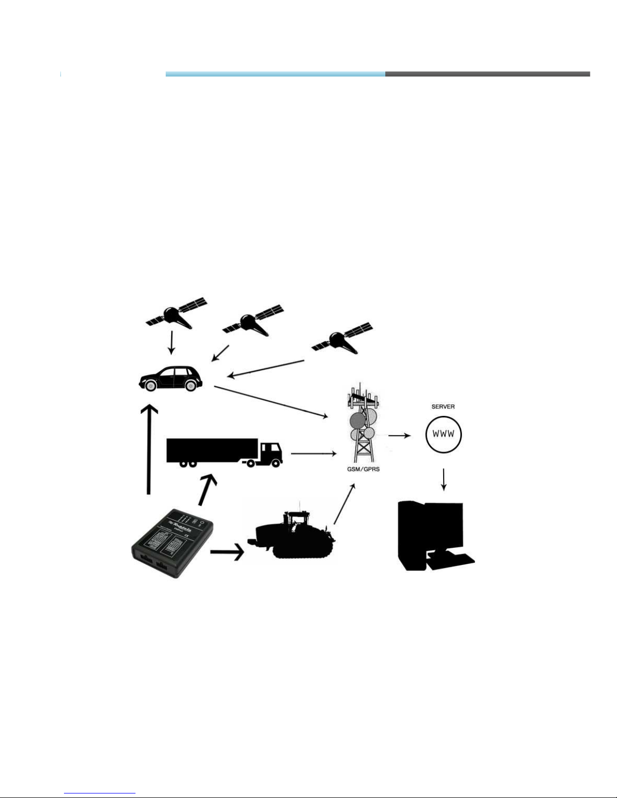
FM-Tco3 is a Terminal with GPS/GLONASS / GSM connectivity, which is able to determine the
object’s coordinates and transfer them via the GSM network. This terminal is perfectly suitable for
applications where location acquirement of remote objects is needed. It is important to mention
that FM-Tco3 has additional inputs and outputs, which let control and monitor other remote
objects. 1-Wire® interface (for Dallas digital thermometer or I-Button reader) and CAN-bus
interface integrated (for trucks FMS interface data acquisition). It also has 2 simplified RS232 ports
for connecting additional equipments such as Personal Navigation Device, digital fuel level sensor
or other (special firmware is needed for this).
Figure1. Example of application of GPS/GLONASS/GSM terminal FM-Tco3 for controlling and monitoring of remote
objects.
FM-Tco3
Page 26
© All rights reserved to Ruptela UAB
P a g e |
26
4.2. BASIC DESCRIPTION
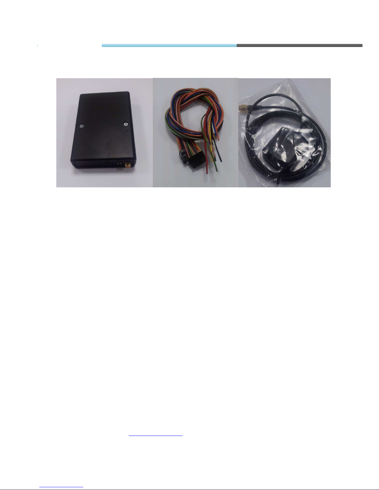
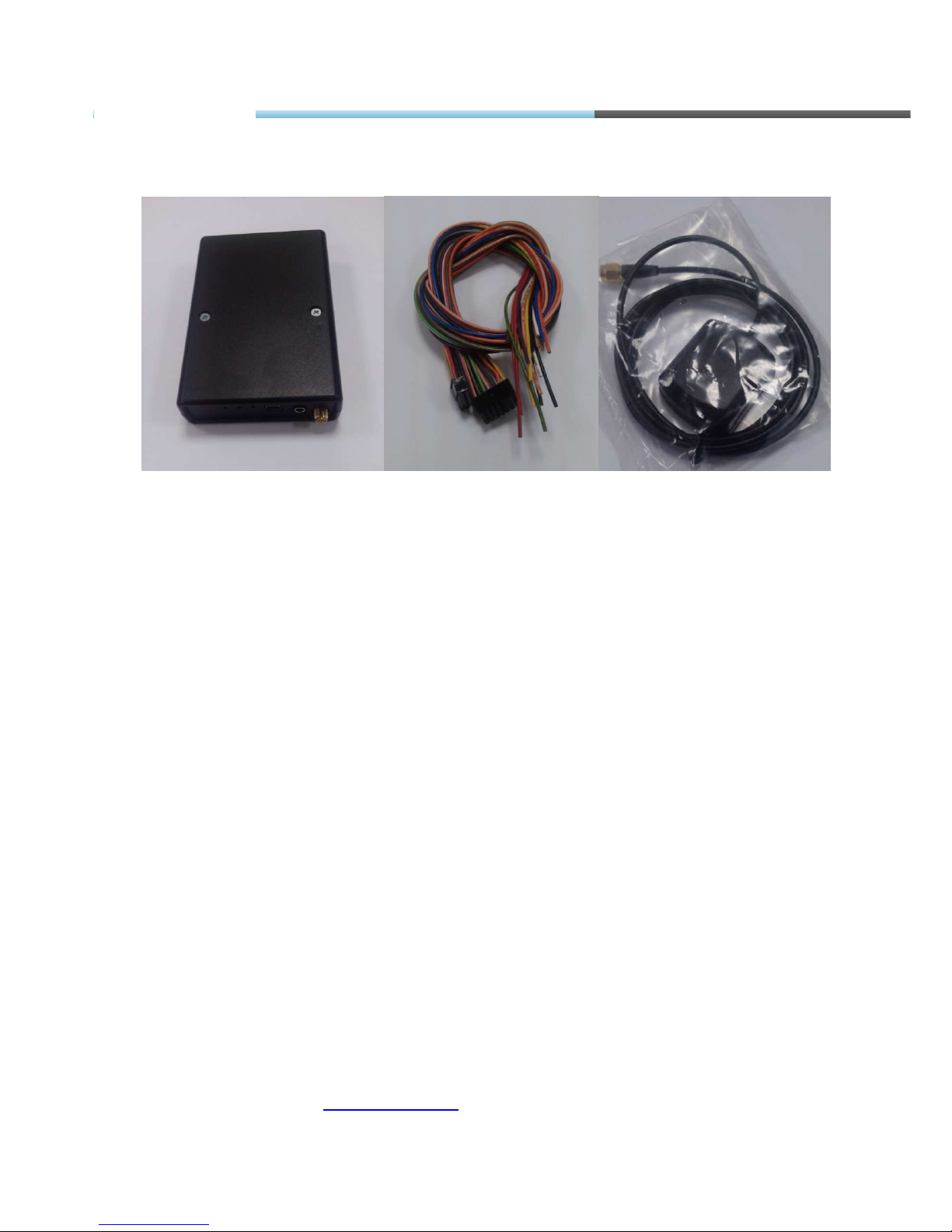
Figure2. FM-Tco3 device, power and I/O cables and GPS/ GLONASS antenna.
The FM-Tco3 device is supplied to the customer in a cardboard box containing all the
equipment that is necessary for operation. The package contains:
• The FM-Tco3 device.
• 10 PIN plug with wires for power supply and I/O connection
• Magnetic GPS/GLONASS antenna with sticker.
• 14 PIN plug with wires for CAN-bus, 1-Wire, 2 simplified RS232, RS485 and K_line, L_line
connection.
4.3. ADDITIONAL ACCESSORIES
There are a few standard accessories available for FM-Tco3 that is not included in the package:
• Analog Temperature sensor;
• 1-Wire Digital Temperature Sensor DS18B20 / DS18S20;
• I-Button.
Note: the manufacturer does not supply a SIM card in the package, which is necessary for
connection to the GSM network! SIM card can be obtained from your local GSM service provider!
SIM card can work with the Terminal only when all SIM card security codes are disabled!
If any of the components are not in the package, please contact the manufacturer’s
representative or the vendor (
www.ruptela.com).
FM-Tco3
Page 27
© All rights reserved to Ruptela UAB
P a g e |
27
4.4. BASIC CHARACTERISTICS
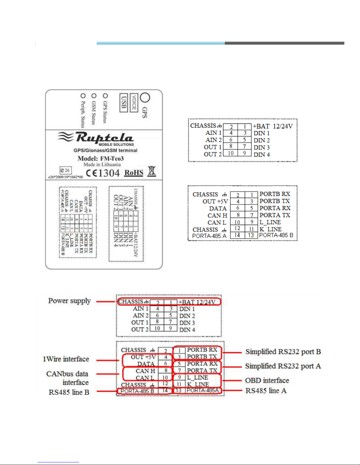
Inputs / Outputs:
IO1 – 10 pin (2x5 plug):
IO2 – 14 pin (2x7 plug):
Paired connection scheme:
Other Inputs / Outputs are not paired. Also two spare Chassis pins can be paired with any I/O,
they are only for easier mounting.
FM-Tco3
Page 28
© All rights reserved to Ruptela UAB
P a g e |
28
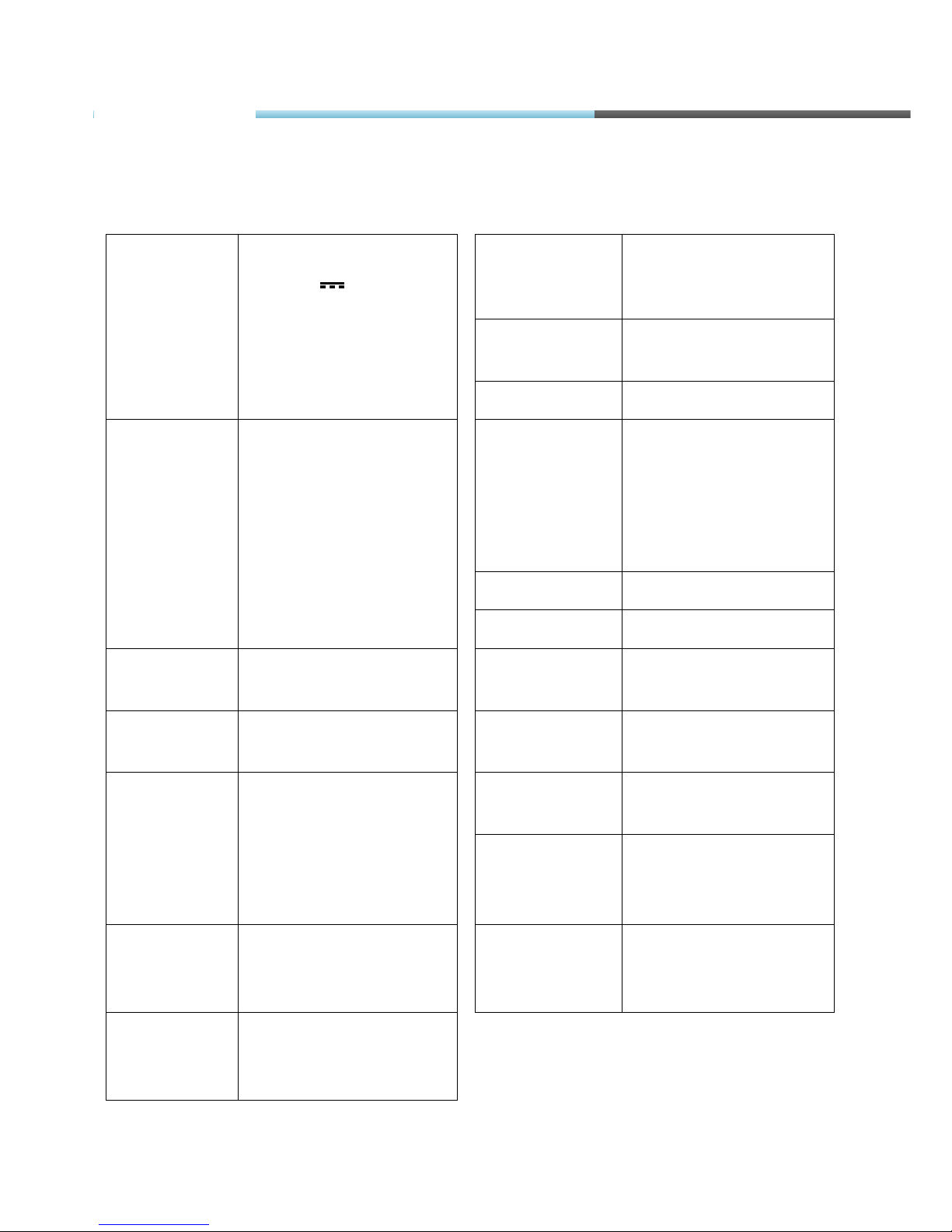
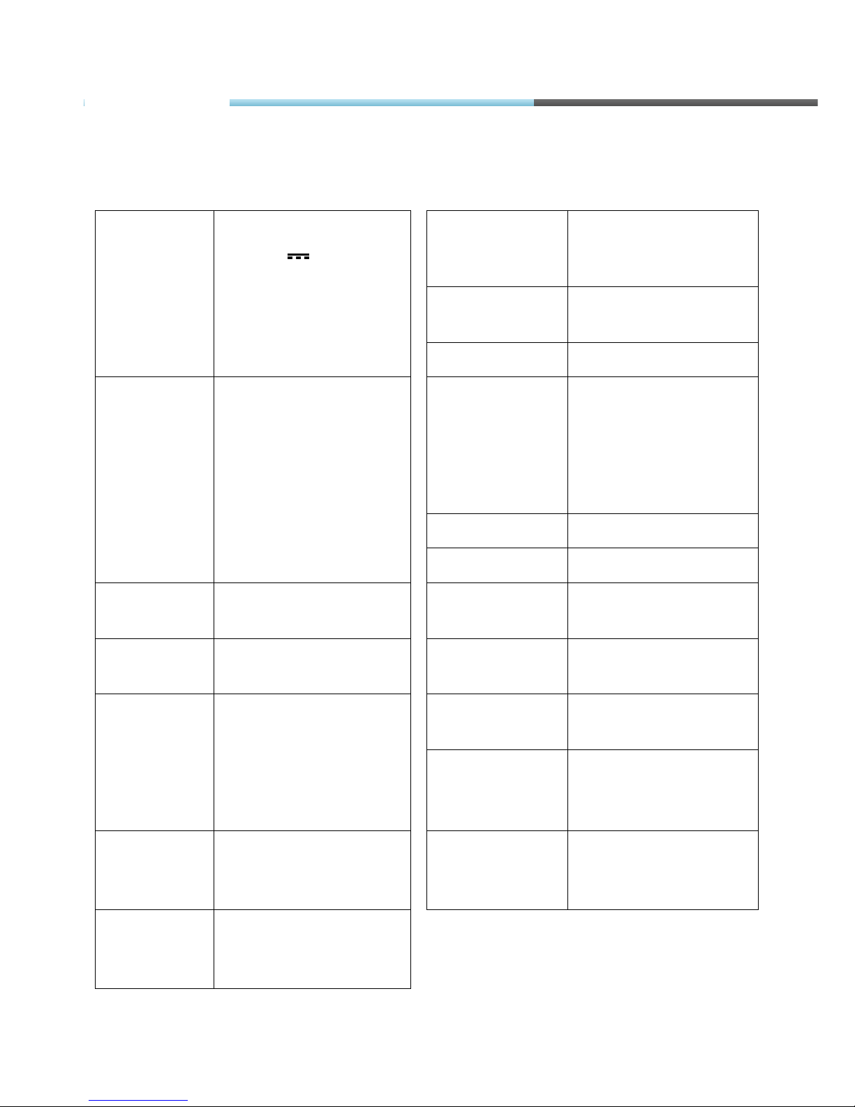
4.5. TECHNICAL FEATURES
Power supply
External Battery Ratings:
+12/24V 1A/500mA
Internal battery Ratings:
Li-Po 3.7V 680 mAh (up
to 3 hours)
GPS Ublox module (with
external GPS/GLONASS
antenna)
GPRS/GSM Simcom module (with
internal GSM antenna)
Accelerometer LIS3DH accelerometer
Fuses External fuse (mounted
into +BAT wire):
F 2AL
Internal fuse (mounted
into internal battery
module):
SMD 2A
LED’s GPS fix LED,
GSM LED,
Peripheral LED,
All LED’s are green.
Mini USB Mini USB socket
SIM Sim card holder with lock
Dimensions 111.25 x 75 x 25.2 mm
10 pin plug For ex. Tyco multi-lock
4-794619-0 socket
Weight 140g
14 pin plug For ex. Tyco multi-lock
4-794619-4 socket
Temperatures Operational temp.:
-35°C ... +55°C
Storage temp.:
-40°C ... +65°C
Housing /
Material
UL94-HB Plastic case
2x Simplified
RS232 ports
PORTA Rx, Tx
PORTB Rx, Tx
Micro SD Micro SD card holder
TRRS connector 3,5 mm TRRS connector
for handle speaker and
microphone
RS485 port PORTA – 485
FM-Tco3
Page 29
© All rights reserved to Ruptela UAB
P a g e |
29
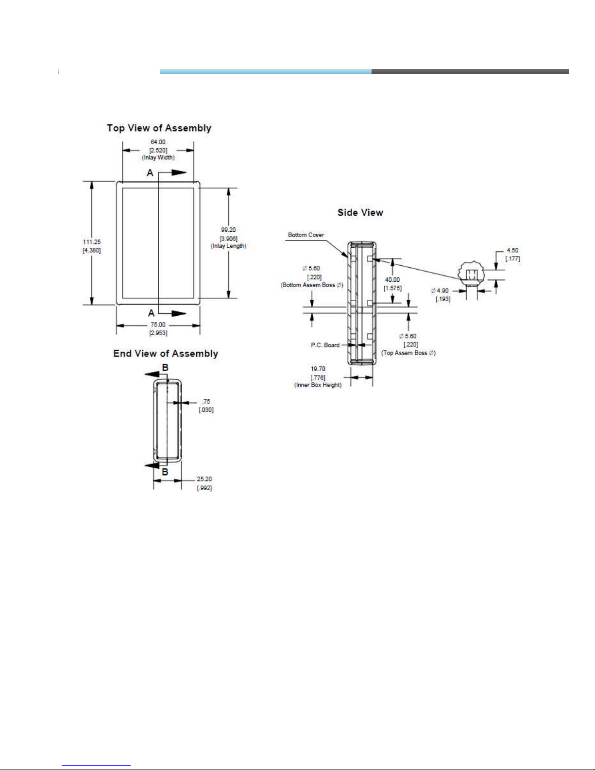
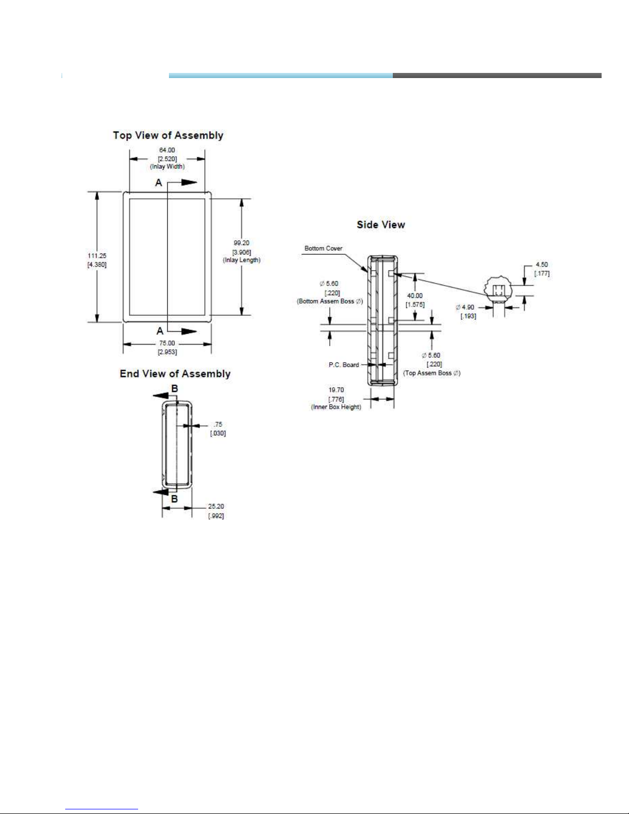
4.6. FM-TCO3 DIMENSIONS
FM-Tco3
Page 30
© All rights reserved to Ruptela UAB
P a g e |
30
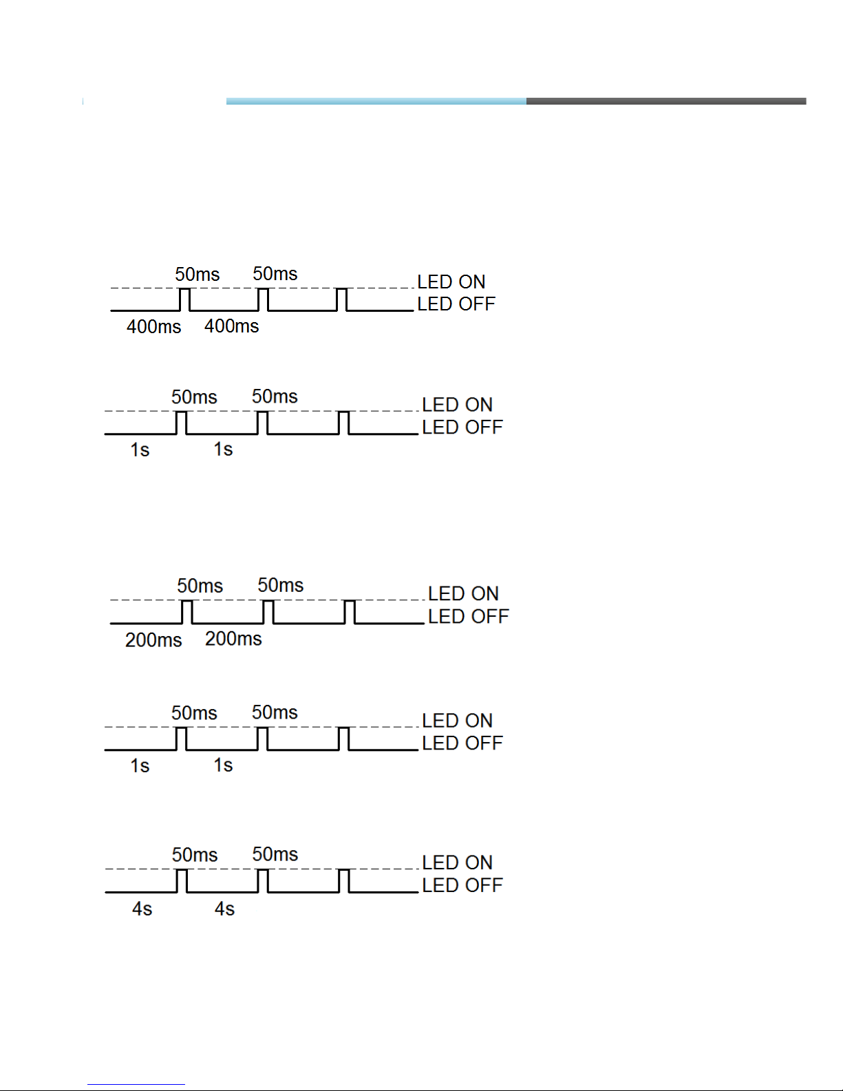
4.7. LED STATUSES
GPS LED
When GPS/GLONASS signal is not received or GPS/GLONASS signal is not accurate, the GPS
LED is blinking as follows:
When accurate GPS/GLONASS signal is received, the GPS LED is blinking as follows:
GSM LED
When GSM signal is not received, GSM LED is blinking as follows:
When device has a good GSM signal, but no GPRS, LED is blinking as follows:
When device has good GSM signal and it is connected to GPRS, then LED is blinking as
follows:
FM-Tco3
Page 31
© All rights reserved to Ruptela UAB
P a g e |
31
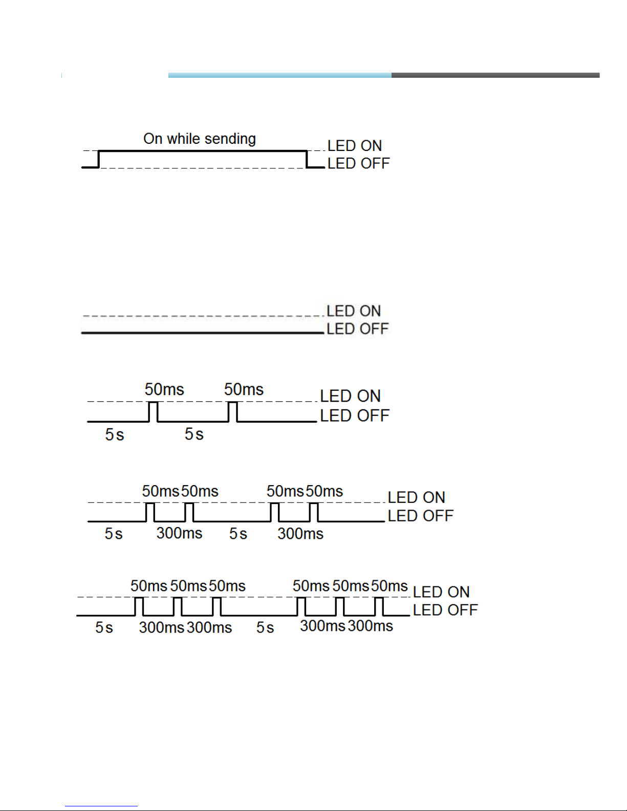
When the FM-Tco3 terminal has GSM signal and it is sending data via GPRS, LED is blinking:
Peripheral LED
To the FM-Tco3 terminal there can be up to three peripheral interfaces attached. So there are 3
different types of blinking when one or other peripheral is connected.
When there is no peripheral attached, LED will not blink at all:
When there is 1 out of 3 peripheral interfaces connected, Peripheral LED is blinking:
When there are 2 out of 3 peripheral interfaces connected, Peripheral LED is blinking:
When there are 3 out of 3 peripheral interfaces connected, Peripheral LED is blinking:
FM-Tco3
Page 32
© All rights reserved to Ruptela UAB
P a g e |
32
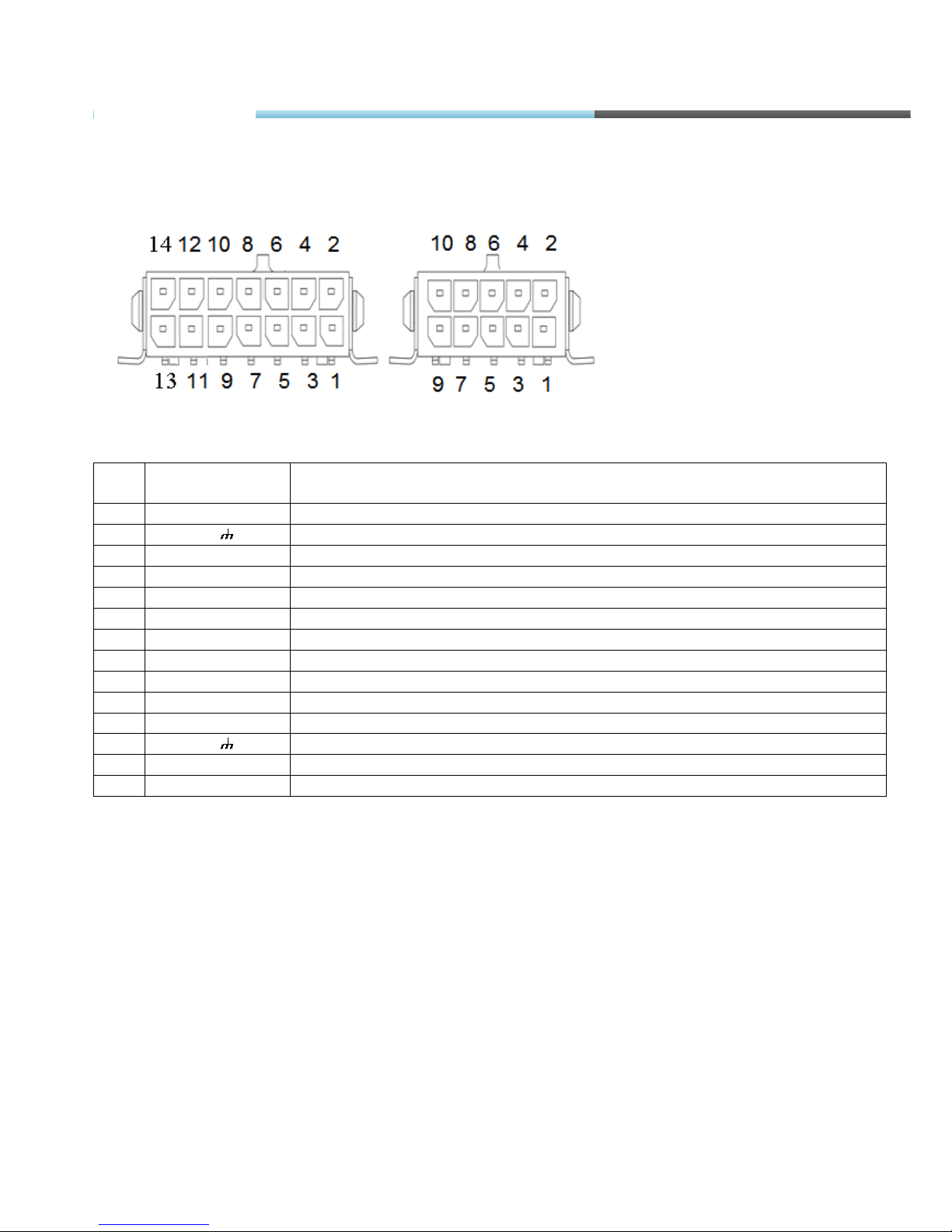
4.8. PINOUT CONNECTION, USB
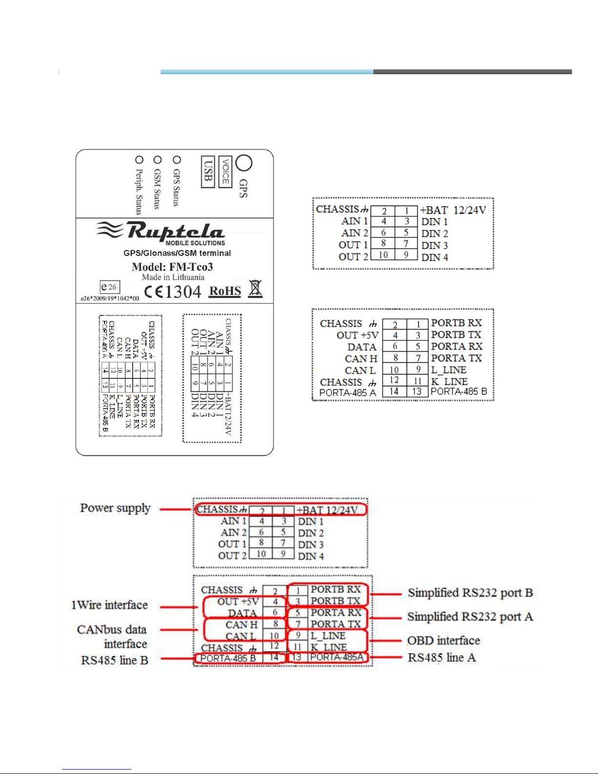
FM-Tco3 standard plugs, 14 and 10 PINs.
Standard FM-Tco3 14 PINs plug description:
Pin
No.
Pin name
Description
1. PortB RX Port B receive signal
2. Chassis The frame or chassis of a car.
3. PortB TX Port B transit signal
4. OUT +5V +5V output for Dallas 1-Wire® devices (max 20 mA)
5. PortA RX Port A receive signal
6. Data Data channel for Dallas 1-Wire® devices
7. PortA TX Port A transit signal
8. CAN H SAE J1939 CAN interface High channel
9. L_Line SAE J1939 CAN interface L_Line channel, diagnostics
10. CAN L SAE J1939 CAN interface Low channel
11. K_Line SAE J1939 CAN interface K_Line channel, diagnostics
12. Chassis The frame or chassis of a car
13. PORTA-485A RS-485 differential signaling line A
14. PORTA-485B RS-485 differential signaling line B
TRRS connector is used for connecting speaker and microphone to FM device. Communication is
half-dulpex, so you can’t listen and speak at the same time (you have to use a switch). To initialize
a conversation - you need to call from your phone to SIM card number, which is inside the device.
Device will automatically answer this call. More information about TRRS is stored in TRRS
connector specification.
FM-Tco3
Page 33
© All rights reserved to Ruptela UAB
P a g e |
33
Standard FM-Tco3 10 PINs plug description:
Pin
No.
Pin name
Description
1. +BAT 12/24V Battery rated voltage: 12/24V.
Allowed battery voltage range
: 10...32V
2. Chassis The frame or chassis of a car
3. DIN 1 Digital input, channel 1(It can be also used as a pulse counter).
Threshold 4V
4. AIN 1 Analog input, channel 1. Input range: 0 – 30V
5. DIN 2 Digital input, channel 2(It can be also used as a pulse counter).
Threshold 4V
6. AIN 2 Analog input, channel 2. Input range: 0 – 30V
7. DIN 3 Digital input, channel 3. Threshold 4V
8. OUT 1 Digital output. Channel 1. Open collector output. Max. 32V 250 mA
9. DIN 4 Digital input, channel 4. Threshold 4V
10. OUT 2 Digital output. Channel 2. Open collector output. Max. 32V 250 mA
USB
Pin No.
Pin name
Description
1. VBUS Power
2. D- Data -
3. D+ Data +
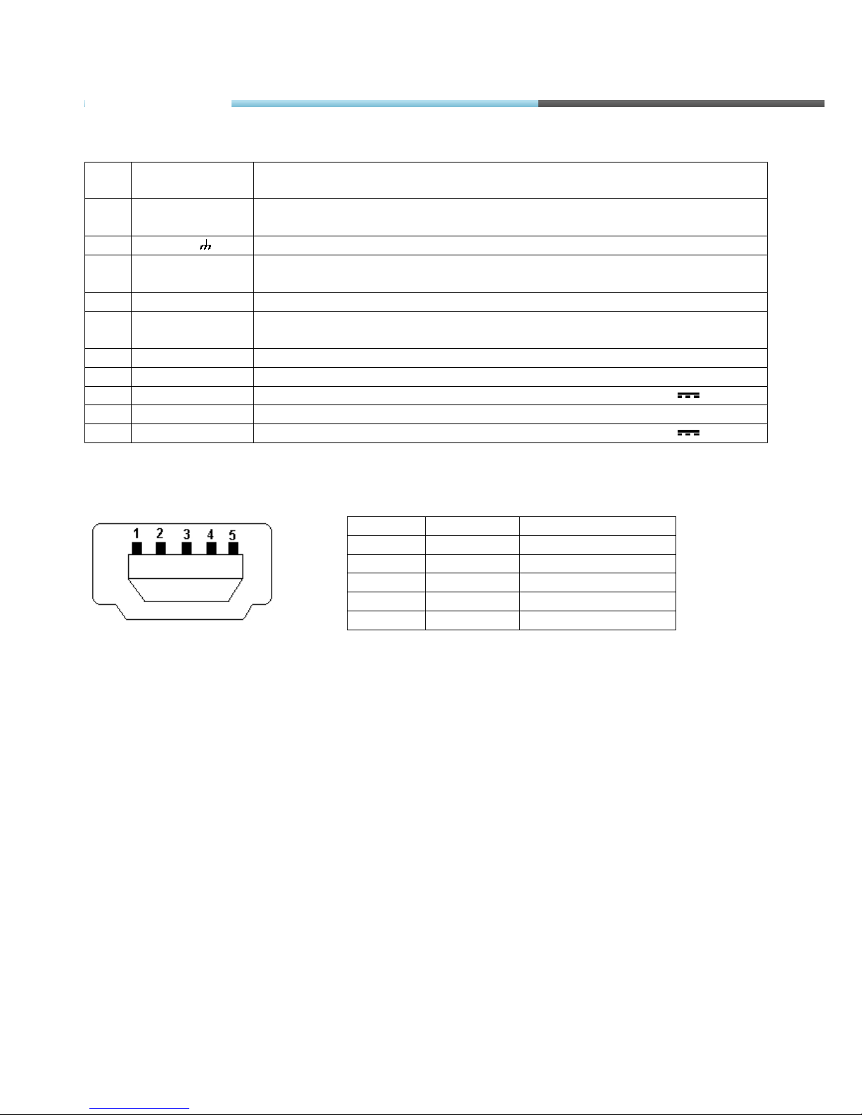
4. ID NC
5. GND Ground
4.9. SPECIAL FEATURES
• Any element event triggers (external sensor, input, speed, temperature, etc.);
• Smart profile switching (GSM operator or any element depended);
• Highly configurable data acquisition and sending (incl. data from tachograph*);
• Real-time process monitoring;
• Authorized number list for remote access;
• Firmware update via GPRS or Mini USB port;
• Configuration update via GPRS, SMS or Mini USB port;
• TCP/IP or UDP/IP protocol support;
• 16 000 record storing (without micro SD card).
FM-Tco3
Page 34

© All rights reserved to Ruptela UAB
P a g e |
34
• Up to 32 GB micro SD card as Flash memory extension.
• Ability to connect speaker/ microphone (with switching capability) through 3,5 mm TRRS
connector.
* Data from tachograph: vehicle's VIN and registration numbers, driver's identification number, driver's state
(Rest/Work/Drive/Available), driver card status (inserted/removed), total distance, trip distance, speed, RPM.
4.10. QUALIFICATION AND CERTIFICATION
The FM-Tco3 terminal complies the essential requirements detailed in the following Articles of
the Directive:
Essential Requirements
Conformed Specifications / Standards
Safety
R&TTE, Article 3.1(a)
EN 60950-1:2006+A11:2009
EMC
R&TTE, Article 3.1(b)
EN 301 489-1 V1.6.1
EN 301 489-7 V1.3.1
Radio Spectrum
R&TTE, Article 3.2
EN 301 511 (v9.0.2)
Environmental testing. Part 2-64. Tests –
Test Fh: Vibration, broadband random and
guidance (IEC 60068-2-64:2008)
LST EN 60068-2-64:2008
FM-Tco3
Page 35
© All rights reserved to Ruptela UAB
P a g e |
35
5. INSTALLATION AND CONFIGURATION INSTRUCTIONS
5.1. MODULE INSTALLATION
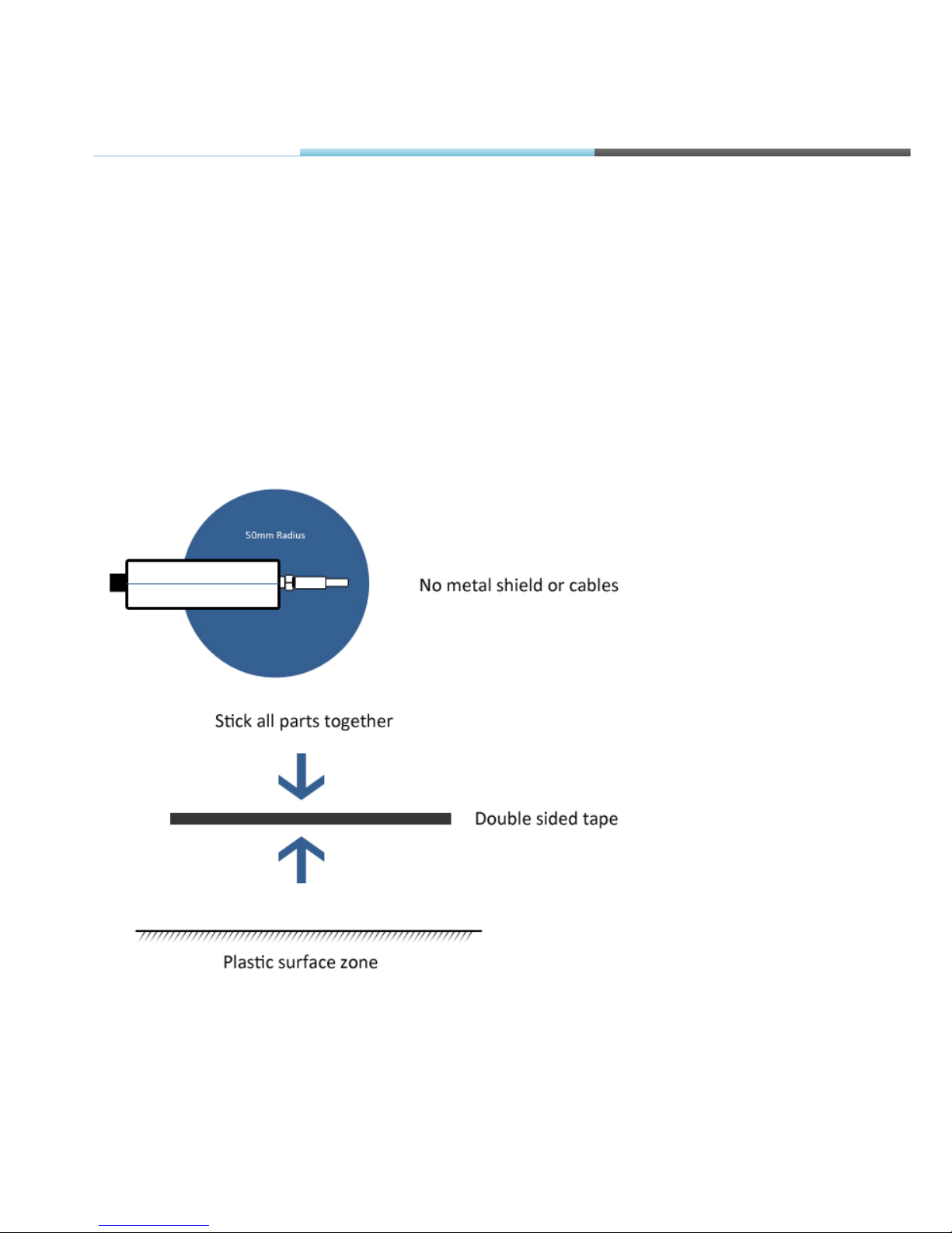
• Module should not be seen or easily reached.
• Module should be firmly fixed to the surface. Please avoid mounting module near the metal
surface or cables (see the picture below). Wrong module mounting may be the cause of
module malfunction.
• Module cannot be fixed to heat emitting or moving parts.
• SIM card should be inserted in the module while the connector is plugged off (while module has
no power).
• Module must be fitted with double sided stick tape!
FM Manual
Page 36
© All rights reserved to Ruptela UAB
P a g e |
36
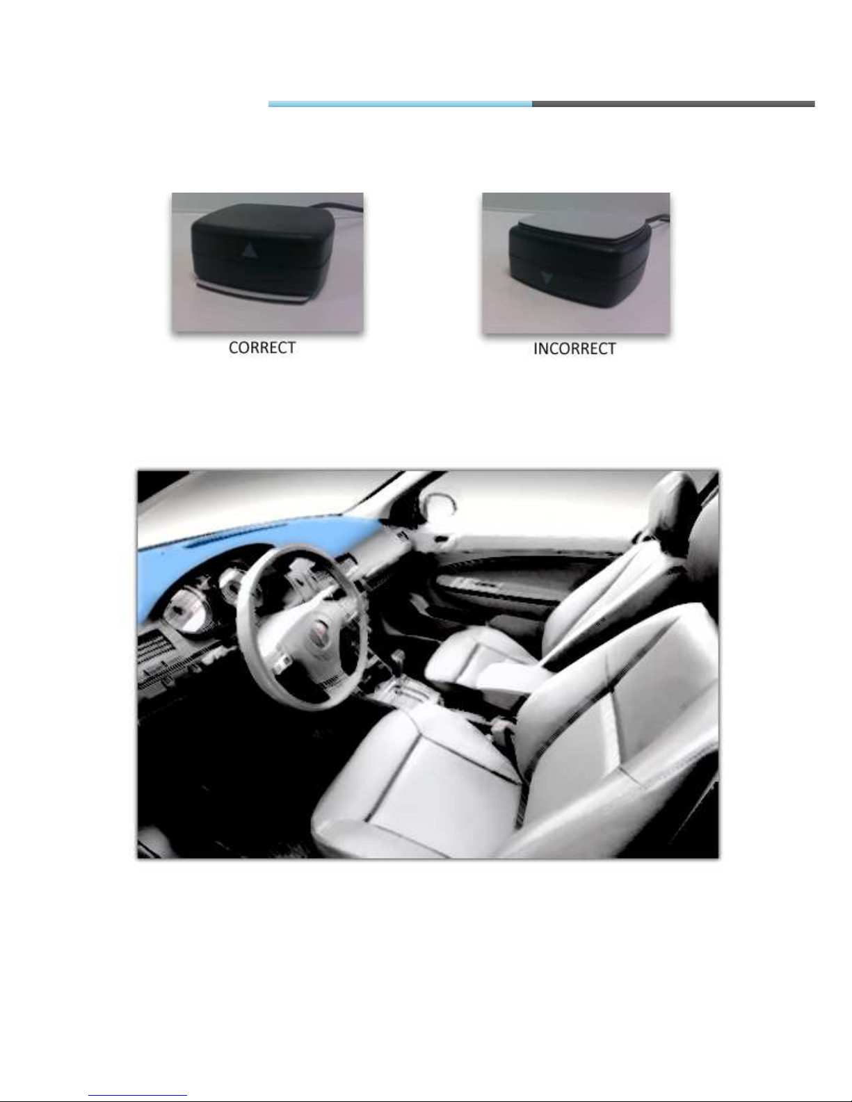
GPS/GLONASS antenna connection
It is recommended to place GPS/GLONASS antenna behind the dashboard as close to the
window as possible. A good example of GPS/GLONASS antenna placement is displayed in a
picture below (area colored in blue).
FM Manual
Page 37
© All rights reserved to Ruptela UAB
P a g e |
37
5.2. DEVICE CONNECTION TO A PERSONAL COMPUTER
All examples of connection and configuration will be provided on a personal computer
(PC) running Microsoft Windows XP SP3 32bit operating system. Usually identical or analogue
procedures should be applied on newer versions of Windows family operating systems.
5.2.1.SYSTEM REQUIREMENTS
Hardware requirements:
• CPU: 1,5GHz or better.
• RAM: 512MB or more.
• USB port
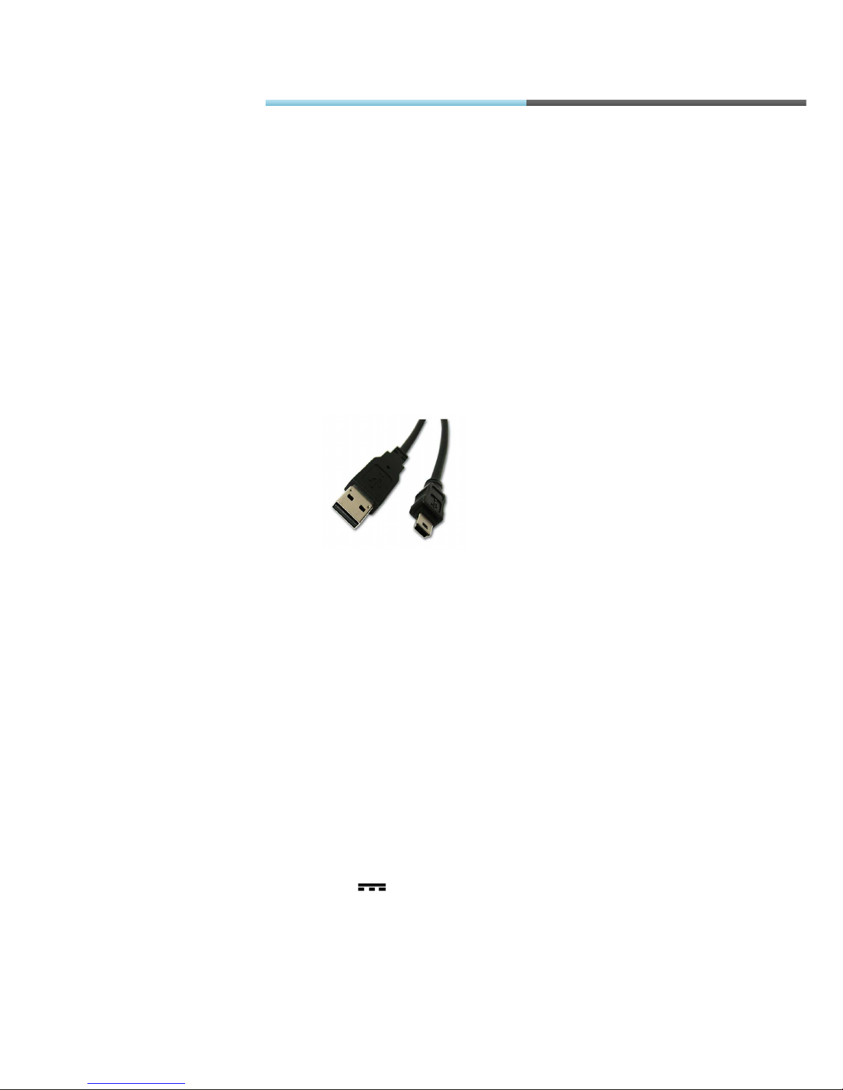
• USB A to mini USB cable (Fig.5.2.1.1)
o Software requirements
• Operating system: Microsoft Windows XP, or Microsoft Windows Vista, or Microsoft
Windows 7 (32-bit and 64-bit)
• Microsoft .NET framework 4 (available as a free download from
http://www.microsoft.com/downloads/en/details.aspx?FamilyID=9cfb2d51-5ff4-4491-b0e5b386f32c0992 ).
5.2.2.PREPARATION FOR CONNECTION
Before connecting FM Terminal to PC please check if you have the latest configuration software.
You can download it from here: ftp://dev.ruptela.lt (user name:ftp, password: ftp).
At first connect device to +12/24V 1A/500mA power supply, this will prevent from
damaging PC when FM device is active. You can use an AC/DC stabilized converter for this (not
supplied with the device). When the device is powered up, it is safe to plug in USB cable.
FM Manual
Fig. 5.2.1.1 USB A to mini USB cable.
Page 38
© All rights reserved to Ruptela UAB
P a g e |
38
5.2.3.DRIVER INSTALLATION
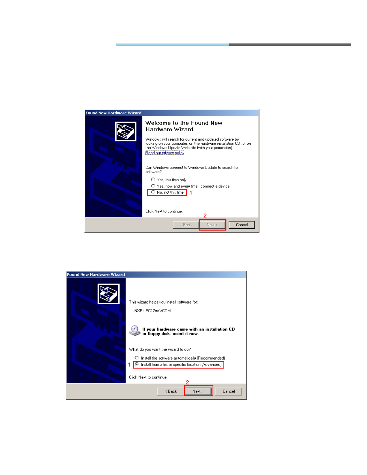
1. When the FM device is connected to PC for the first time, a notification should pop up
that new hardware was found and configuration window is shown (Fig. 5.2.3.1). Select
„No, not this time“, and click button „Next“.
2. In the next window select „Install from a list or specific location (Advanced)“ (Fig.
5.2.3.2.).
Fig. 5.2.3.2. Driver installation
FM Manual
Fig. 5.2.3.1. Driver installation
Page 39
© All rights reserved to Ruptela UAB
P a g e |
39
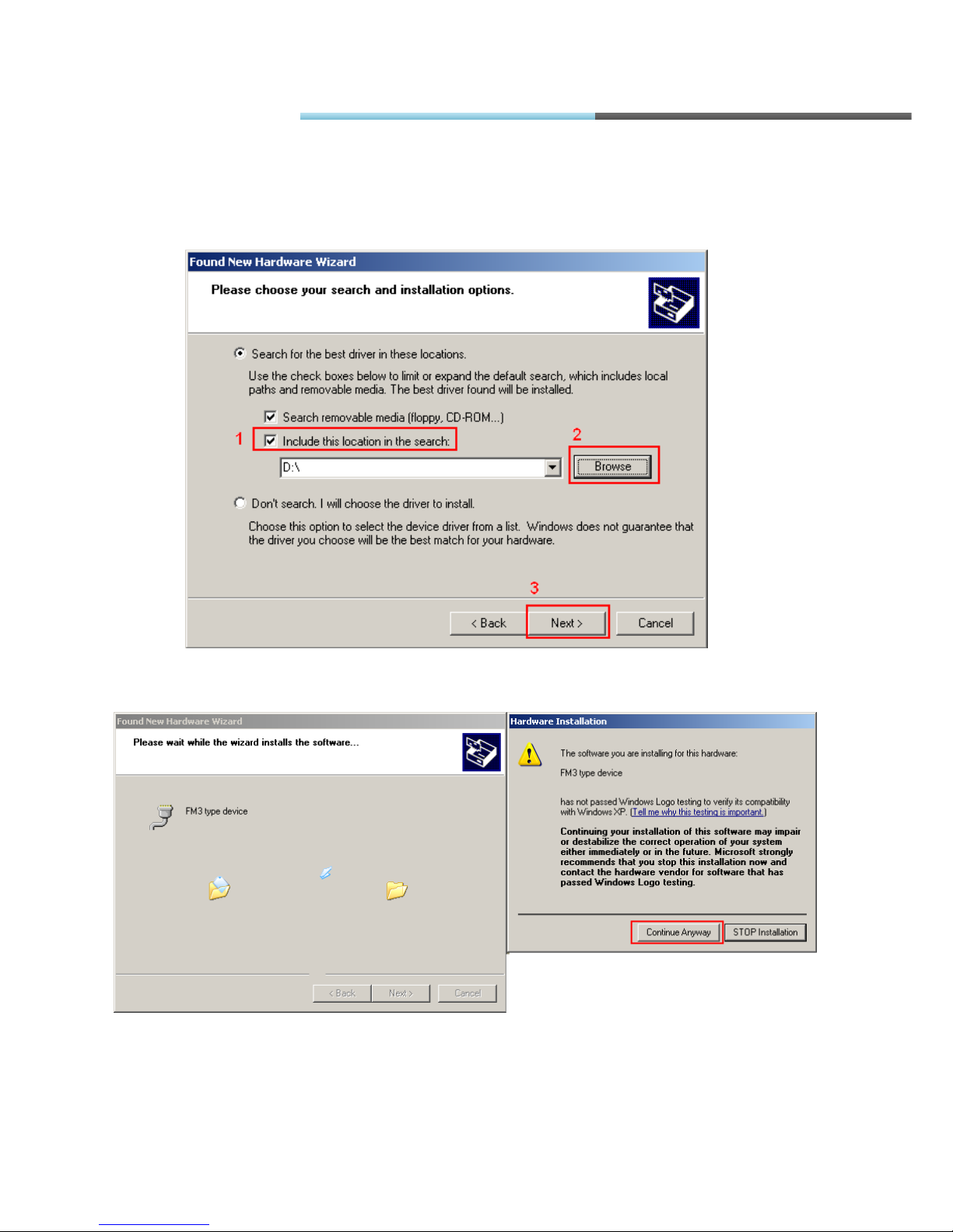
3. In the next window select „Include this location in the search:“ and click „Browse“ and
navigate to folder where configuration software is saved (i.e. F:\FM3 configurator
00.01.15) then click next(Fig. 5.2.3.3.).
4. Then driver installation should proceed. If asked, click „Continue Anyway“ (Fig. 5.2.3.4.).
Fig. 5.2.3.4. Driver installation
Fig. 5.2.3.3 Driver installation
FM Manual
Page 40
© All rights reserved to Ruptela UAB
P a g e |
40
5. The driver should be installed and work.
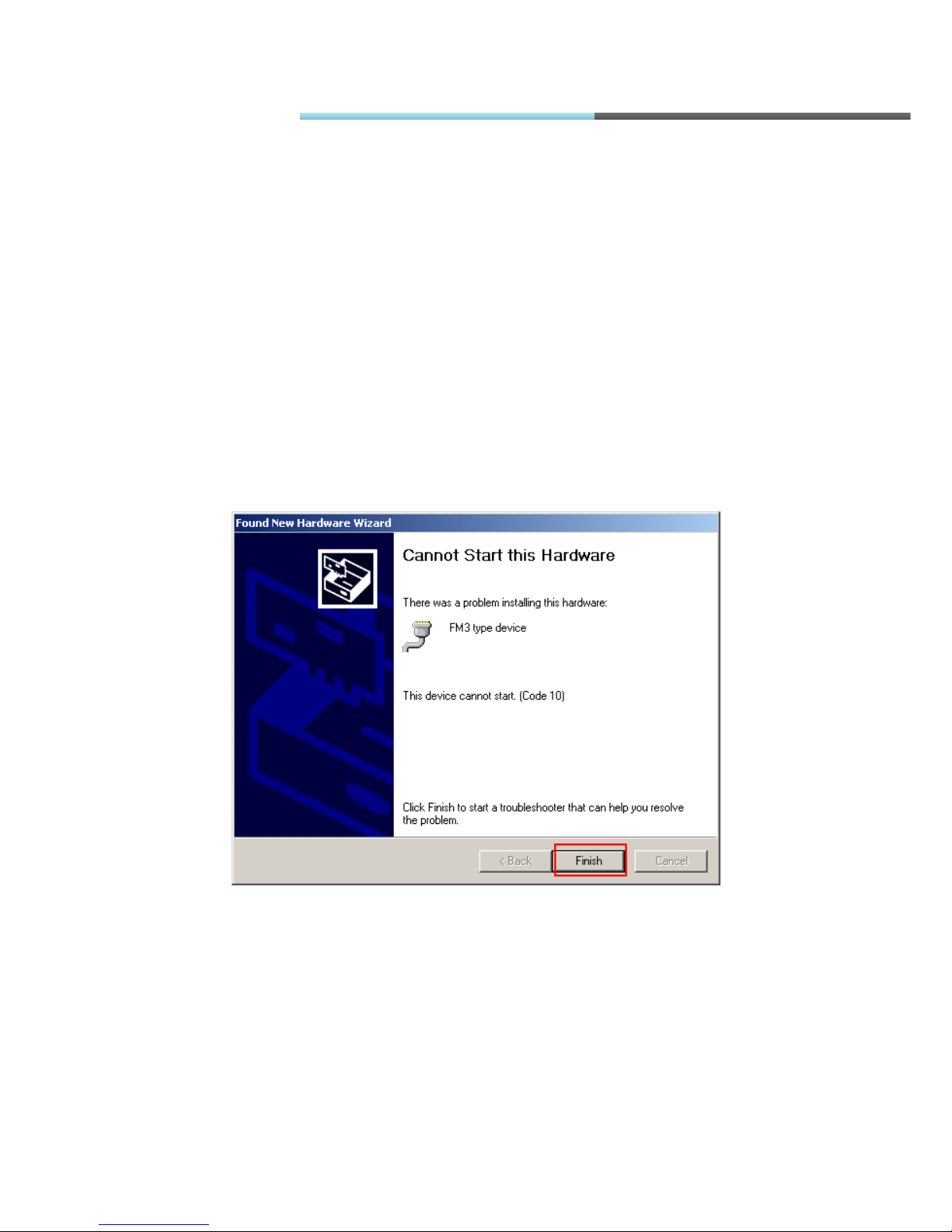
If an error pops up that PC „Cannot Start this hardware“ (Fig. 5.2.3.5.), you should restart
the PC or do the following actions:
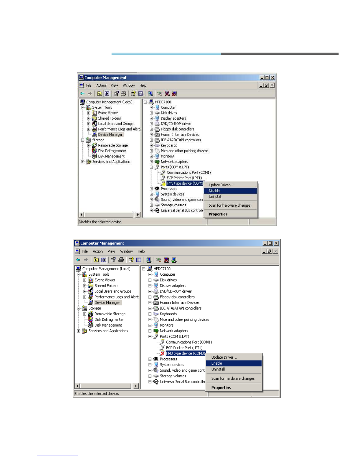
1) Click finish and go to „Device Manager“.
2) In device manager go to „Ports (COM & LPT)“,
3) Expand section then right-click on “FM type device (COMXX)”
4) Select “Disable” (Fig. 5.2.3.6.).
5) When asked for confirmation click “Yes”.
6) Then, again, right-click on “FM type device (COMXX)”
7) Select “Enable” (Fig. 5.2.3.7.).
8) Driver now should be completely installed and ready to use (Fig. 5.2.3.8.)
Fig. 5.2.3.5. Driver installation
FM Manual
Page 41
© All rights reserved to Ruptela UAB
P a g e |
41
Fig. 5.2.3.6. Driver installation
Fig. 5.2.3.7. Driver installation
FM Manual
Page 42
© All rights reserved to Ruptela UAB
P a g e |
42
Fig. 5.2.3.8. Driver installation
5.3. CONFIGURATOR
In order to use configurator go to folder where you saved configuration software and launch
„VCP.exe“ file. This configurator is intended to configure FM-Eco3, FM-Pro3 and FM-Tco3 devices.
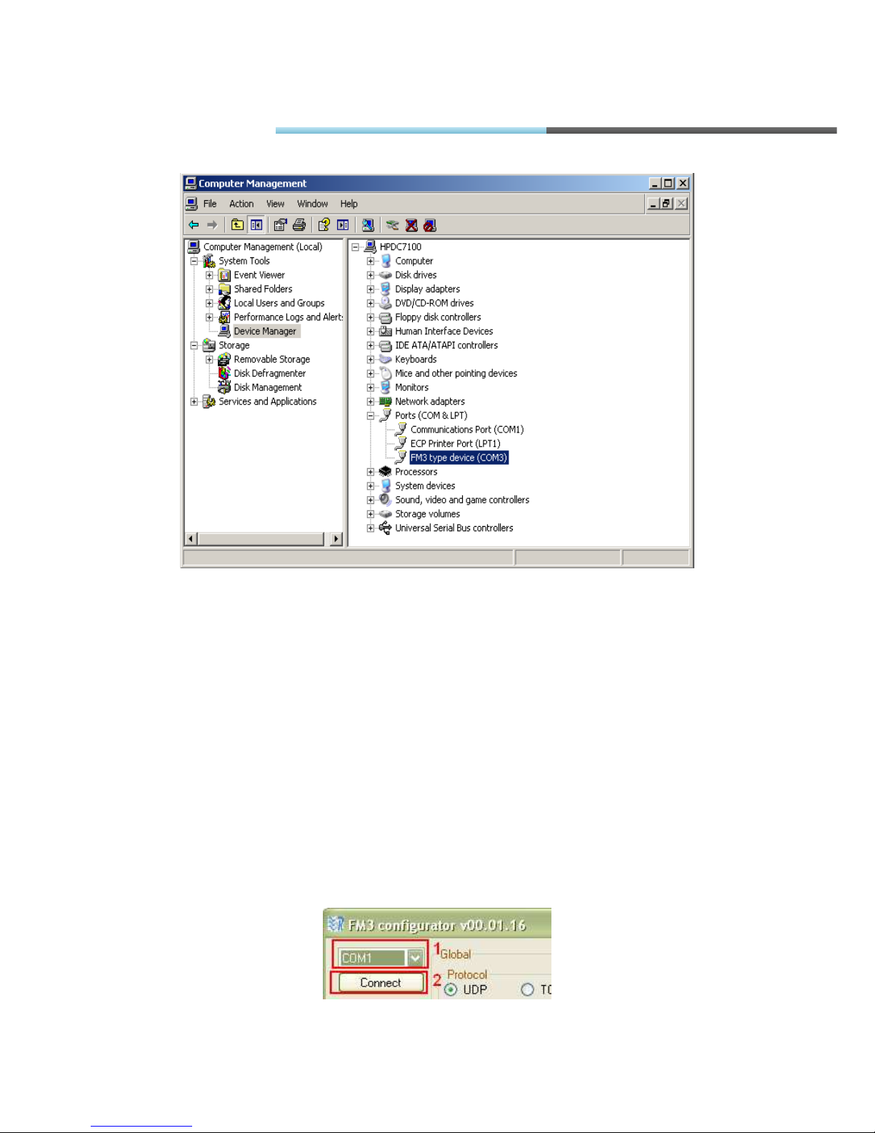
5.3.1.INTERFACING TO COM PORT
In the main view upper left corner there is a drop box which contains COM ports list. You should
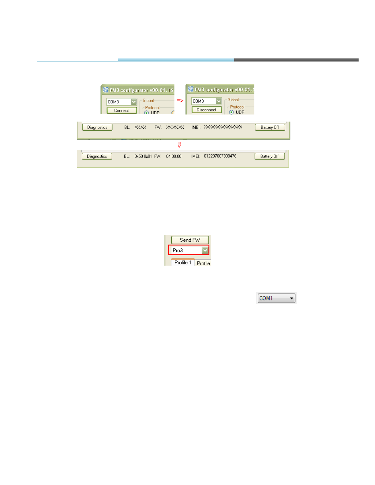
select port corresponding to your device (you can check it in “Device manager”) and click
“Connect” button. If connection is successful, “Connect” button changes into “Disconnect” and in
the bottom of the main view there should be information available about software, hardware and
IMEI number (Fig. 5.3.1.2.). Also while connected, the device type will be detected (Fig. 5.3.1.3.)
Fig. 5.3.1.1 COM port drop-box
FM Manual
Page 43
© All rights reserved to Ruptela UAB
P a g e |
43
Fig. 5.3.1.2 Changes after connection to COM port
In order to disconnect click the “Disconnect” button. Sometimes when connected IMEI is displayed
as a few unconditional characters, this means that device is not fully ready. Try to disconnect, wait
half a minute or longer and connect again – this should fix the problem.
Fig. 5.3.1.3 Device type selection drop-box
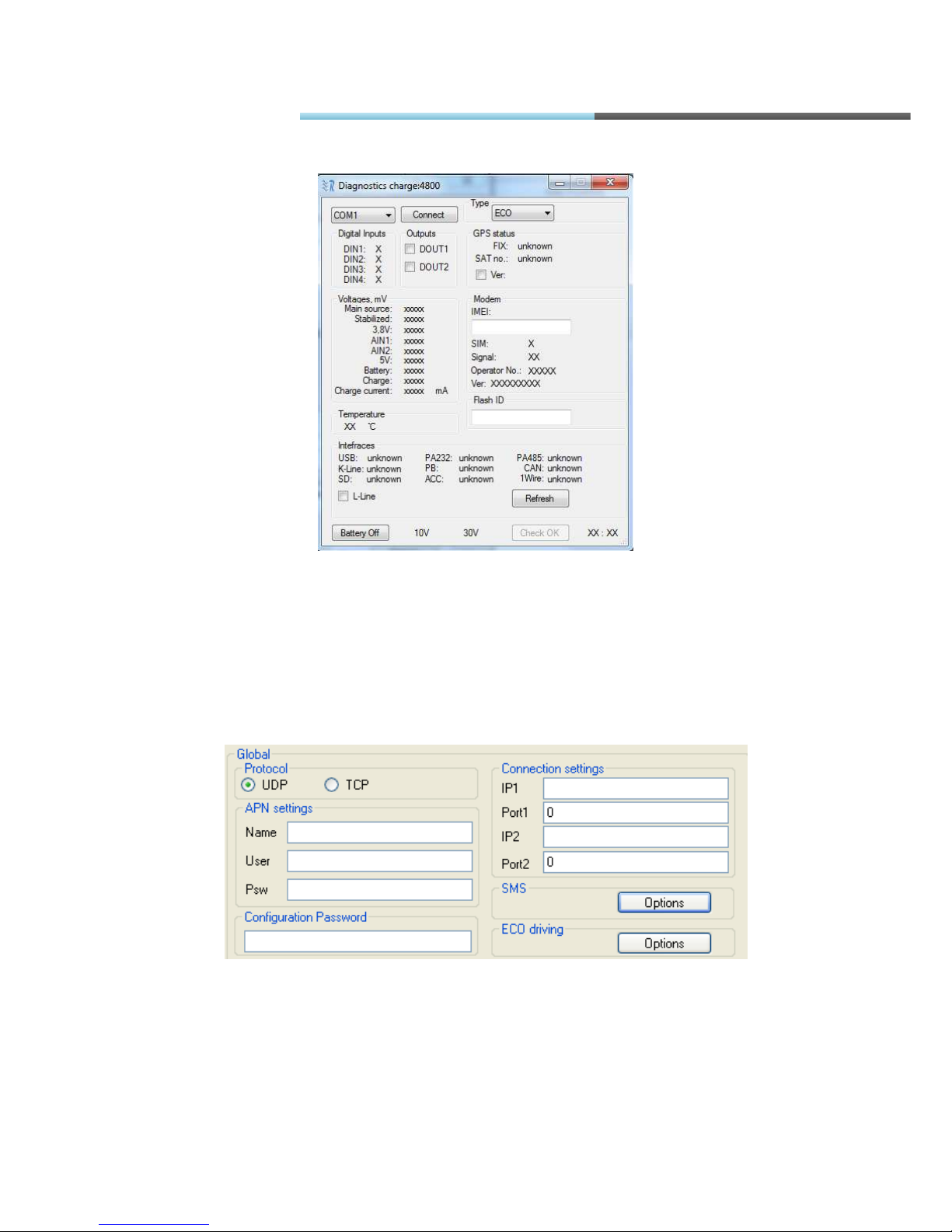
If you want to enter Diagnostics tool, you need to click on COM port (i.e. ) and then
press Ctrl + Alt + D buttons. A new button “Diagnostics” will appear in the left bottom corner. You
will need to connect to exact COM port there. After that you will be able to see:
• Voltage of analog inputs
• Voltage of internal battery and power supply
• Charge current
• Status of digital inputs
• Modem information
• GPS/GLONASS module information
• Digital outputs status (you will be able to change them)
• Modem temperature
• Loopback of different interfaces
FM Manual
Page 44
© All rights reserved to Ruptela UAB
P a g e |
44
Fig. 5.3.1.4. Diagnostics function
5.3.2. GLOBAL PARAMETER CONFIGURATION
Global parameters are parameters which apply to the system in general. Global
parameters are constant and do not change while the device is working, unless they are
configured by user (Fig.5.3.2.1.).
Fig. 5.3.2.1. Global parameter view
FM Manual
Page 45

© All rights reserved to Ruptela UAB
P a g e |
45
Protocol is a formal description of digital message formats and the rules for exchanging those
messages between system’s elements. This parameter sets how FM device communicates with
the server. Options:
• UDP – consumes less traffic (amount of data send/received), but less reliable.
• TCP – consumes more traffic (about 30% more), but more reliable.
In case of UDP, if data is lost during transfer to server, the device will repeat the same message in
next GPRS session, until transfer is successful. This means that in case of UDP there will be more
retries to send, but server will receive all the data anyway.
APN (Access Point Name) is a communication protocol that allows user's device to access the
internet using the mobile phone network. Name, User and Psw (password) parameters should be
provided by your mobile operator as GPRS settings.
Connection settings:
• IP1 – Internet Protocol address of your server in Ipv4 form (i.e. 127.0.0.1)
• Port1 – port number through which server is accessible (i.e. 7001)
• IP2 – second Internet Protocol address of your server in Ipv4 form
• Port2 – alternative port number through which server is accessible
Firslty FM device tries to send data to IP1, if it is valid. If first 5 tries were unsuccessful, device
tries to connect IP2 for five times. If tries are unsuccessful – gets back to first IP.
When connection occured (means that device got a response to it’s sent packet), device sets this
IP (IP1 or IP2) as a primary IP. So all further packets are sent to this primary IP.
After firmware or configuration file update, after restart – primary IP is set to IP1 and device tries to
send data to it.
You can change primary IP (a change between IP1 and IP2) with the help of SMS message. You
can find examples of such messages in additional manual of SMS commands.
Configuration Password – password which restricts device configuration through USB cable.
When it is not blank, you will be asked to enter the password every time when you start receiving
or sending configuration session with device. Leave it blank, if you want everyone to be able to
configure your device. If you forget the password, you can reset or delete it by sending
configuration via GPRS from your server account, because then you will not be requested for
password.
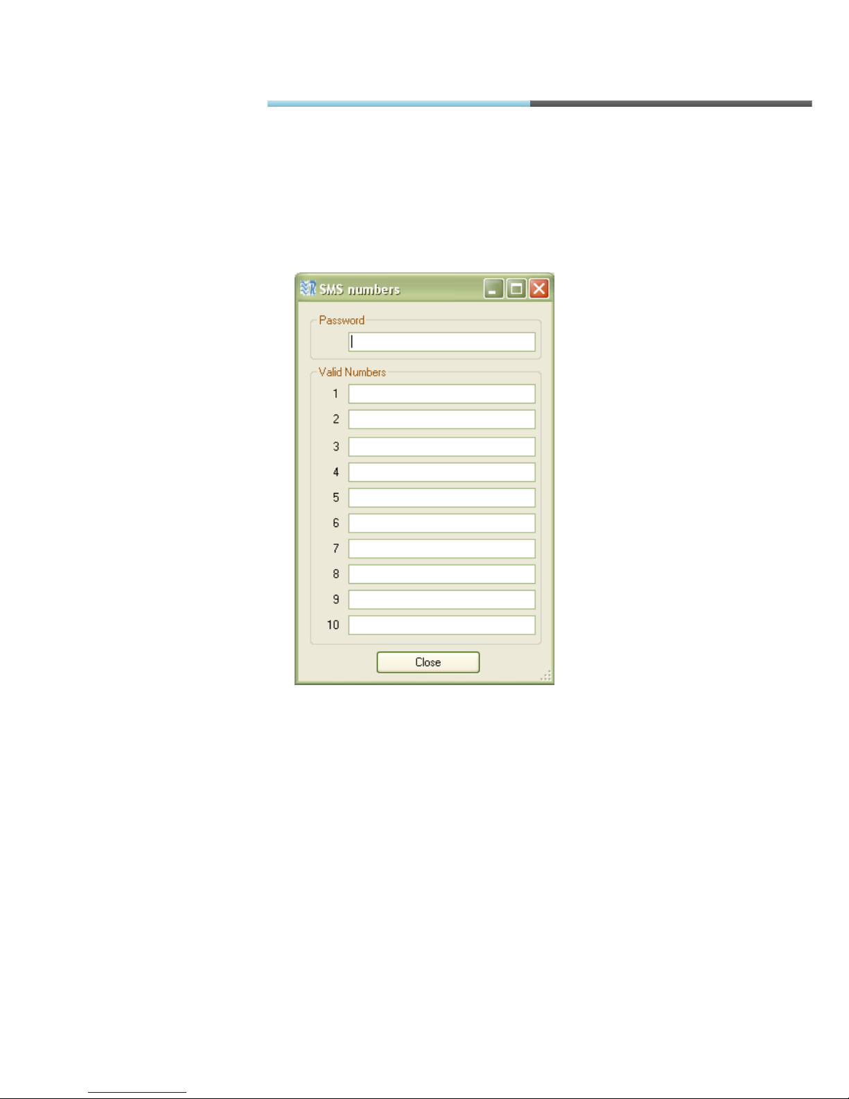
SMS are group of settings to manage your device via SMS messages. Click “Options” to see them
(Fig. 5.3.2.2.). FM device can accept and send specific SMS messages, like device location
information or status. In order to prevent third party eavesdropping you can restrict their usage to
FM Manual
Page 46
© All rights reserved to Ruptela UAB
P a g e |
46
up to 10 authorised numbers with one password for all of them. Device will receive and send SMS
messages only from those Valid Numbers. Numbers are written without spaces and without plus
sign in front (i.e. 37012312345678). Leave them blank, if you want to allow everyone to send SMS
to the device. Every request with SMS must be sent with password, if device is protected. Leave it
blank, if you are not using this feature.
Fig. 5.3.2.2. SMS numbers and password
Warning! If you leave authorised number and password fields empty, then 3rd parties who know
SIM card number will be able to change configuration or do any other action with the device.
ECO driving(only for PRO3 and TCO3 devices) - group of settings, where you can choose
profiles with calculated parameters for trucks, light vehicles or write down your own inputs (i.e.
Overspeeding limit, Harsh braking limit, etc.) for your ECO driving functionality.
FM Manual
Page 47
© All rights reserved to Ruptela UAB
P a g e |
47
5.3.3. PROFILE CONFIGURATION
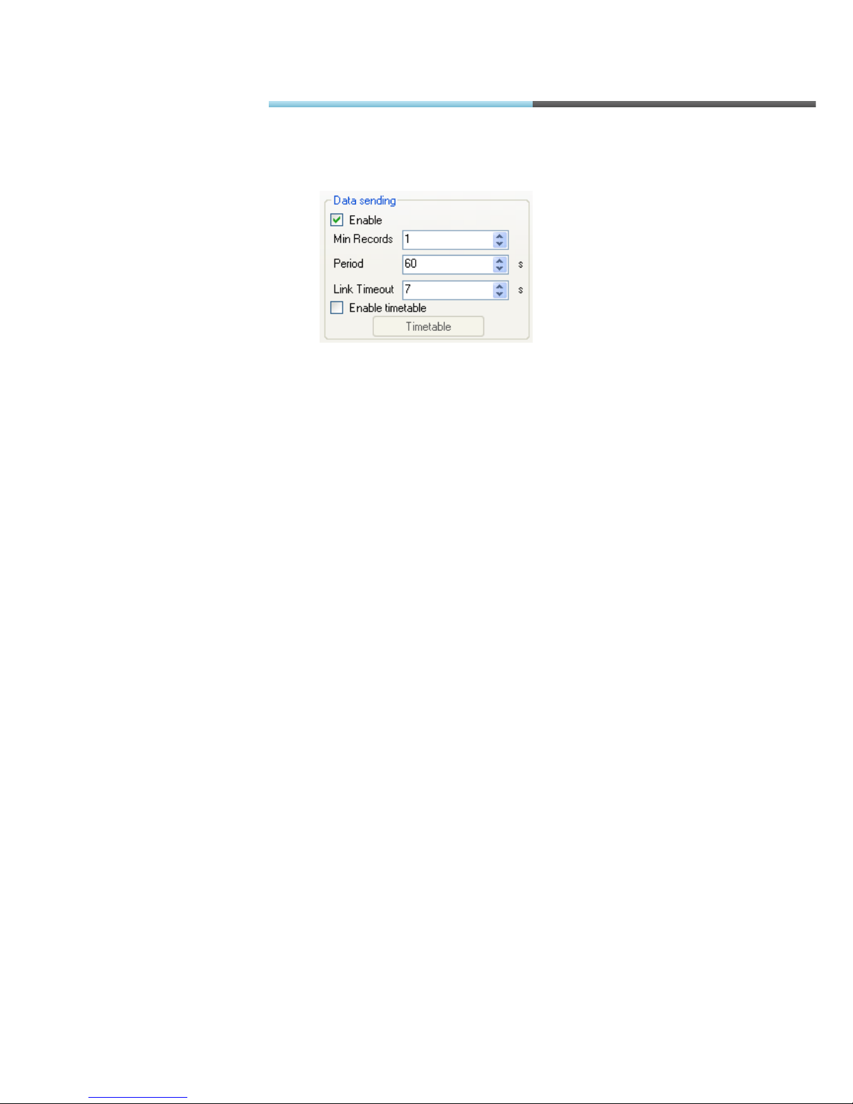
Fig. 5.3.3.1. Data sending options view
Data sending parameters (bottom left) are used to set-up sending rules. User can disable data
sending via GPRS. In this case device will act as black box and only collect records. About 16000
records (without micro SD card) can be stored and after this, device will start overwriting oldest
records. User also defines minimum number of records in order to start session (saves traffic if
your GSM operator has a big session rounding like 10kb or 100kb)and sending period (Fig.
5.3.3.1). “Link timeout” describes, how much seconds system will wait before opening gate to send
records if “Min Records” condition wasn’t fulfilled. System will wait for another “Period” of time to
send records if there weren’t enough records for “Min records” condition after “Link Timeout”
period expires. For advanced sending
rules user can use timetable by enabling it and configuring (click
“Timetable”).
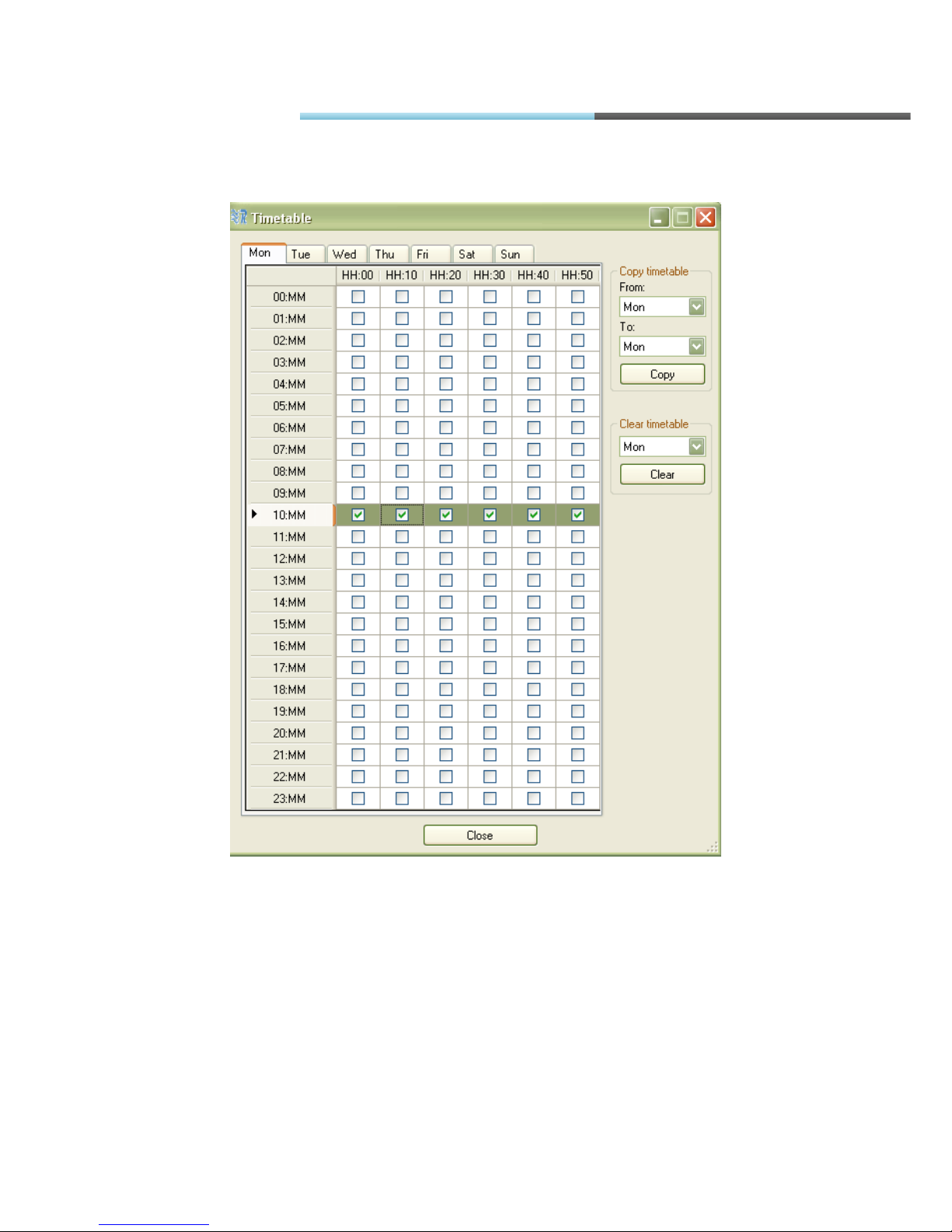
In timetable a week is divided into periods of 10 minutes (Fig. 5.3.3.2.). User can select day of
week and exact time, when GPRS sending is allowed. In order to select/deselect whole hour, user
should click on row header cell. It is possible to configure timetable and copy it to another day of
the week (or whole week). Also similar options are available for timetable clearing. It is important to
note that “Timetable” has a higher priority than “Period” important. Let’s say Period=3600s (1 hour)
and timetable allows sending only from 12:30 to12:40 that day. If sending will start at 00:00, next
time it will send data at about 01:00. Eventually, device will attempt to send 12:00 and 13:00, but
timetable only allows sending 12:30-12:40, so no data will be sent that day. So it is not
recommended to have “Period” longer than the smallest consecutive timetable period (according
to Fig. 5.3.3.2 “Period” should be no longer than 1h=3600s).
FM Manual
Page 48
© All rights reserved to Ruptela UAB
P a g e |
48
Fig. 5.3.3.2. Timetable view
FM Manual
Page 49
© All rights reserved to Ruptela UAB
P a g e |
49
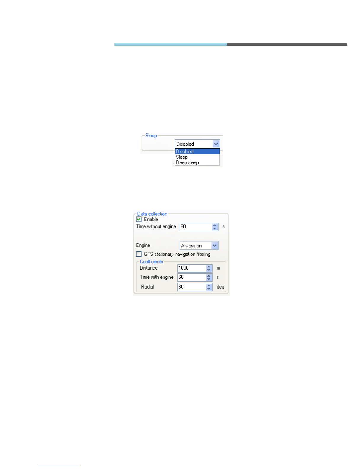
Sleep can be enabled (Fig. 5.3.3.9) to reduce power usage of the device, but sleep also reduces
response from the device, because GSM modem and GPS/GLONASS are switched off (the
device does not collect records based on GPS/GLONASS information and does not respond to
SMS commands). Device enters into sleep mode when no movement or ignition (depends on
“Engine” selection (Fig. 5.3.3.3)) detected for 10minutes. If you have chosen “Deep sleep” –
device will try to enter deep sleep mode after 10 minutes, but if there will be unsent records it will
not enter it. Still, if after next 10 minutes (we mean 20 minutes in total) there will be unsent records
– deep sleep mode will be enabled by force. In deep sleep, not only GPS/GLONASS module and
GSM modem are disabled, but RS232, RS485, 1wire, CAN, OBD K-line and L-line interfaces are
disabled too. Device resumes instantly after ignition detected.
Fig. 5.3.3.9 Sleep selection buttons
Data collection parameters (bottom middle (Fig. 5.3.3.3)) are used to set-up record collection
rules.
Fig. 5.3.3.3. Data collection option view
“Time without engine” sets maximum period within which device must make records. It is mostly
used to make records when device is not moving, so this parameter should not be longer than
“Time with engine“ in coefficients section. “Engine” selection defines how FM device detects
whether it is moving or standing still, this mostly affects record collection time-out:
• “Always on” – device collects records only according to “Time with engine”(i.e. Time without
engine=120s, Time with engine=60s, then it will always collect data with 60s time-out)
• “Ignition (DIN4)” – device considers that it is moving when ignition is turned on ( on digital
input 4 (DIN4) voltage level is high)(i.e. Time without engine=120s, Time with engine=60s,
then if ignition is on time-out will be 60s, if ignition is off time-out will be 120s)
• “MovSensor” – device will take built-in movement sensor data to state if it is moving (i.e.
Time without engine=120s, Time with engine=60s, then if motion sensor detects vibration,
the time-out will be 60s, if no vibrations are detected - time-out will be 120s).
FM Manual
Page 50

© All rights reserved to Ruptela UAB
P a g e |
50
“Engine” selection also defines how device wakes up from the sleep mode. If “Ignition (DIN4)”
mode is selected, then the device will wake up from high level on DIN4. Else (“Always on” or
“MovSensor”) movement will be detected from built-in movement sensor.
“GPS stationary navigation filtering” function filters invalid coordinates, which can occur when
GPS/GLONASS connection is low.
Coefficients section defines how often device collects records based on GPS/GLONASS readings
“Distance” parameter defines what distance a vehicle has to go to make a record. “Time” how
much time must pass to make a record. “Radial” how many degrees a vehicle has to turn to make
a record. All coefficients are counted from last generated record (i.e. Distance=1000m, Time=60s,
Radial=60deg and device was moving for 60s, gone 650m and turned 30 degrees, so record will
be made based on time, and counters will be reset, so device must go for another 1000m, or 60s,
or 60deg to make another record).
FM device has a profiled structure, so according to circumstances device can send, collect and
store the data in different ways. Profile switching is done in two ways: by GSM operator or by IO
event. It is recommended to use single type of switching to avoid confusion. Although advanced
users can combine dual switching. At first, when device starts and has no operator, it jumps to first
profile. As soon as registered to a GSM network, device checks up operator lists (from 1
st
profile to
4
th
) and if it finds GSM operator code (http://en.wikipedia.org/wiki/Mobile_Network_Code) in that
list, it jumps to corresponding profile. If no matching profile list is found, device jumps to first profile
with empty operator list, so it is recommended to leave 4
th
profile with empty operator list. If the
same operator code is entered in two profiles lists, then after the GSM network operator change, it
will jump to first of them – let’s say operator X is listed in 2
nd
profile operator list and 3rd profile
operator list and device works in 1
st
profile, when GSM operator will change to X, device will jump
to 2
nd
profile. If using IO event switching, just set “Switch to” to desired profile (Fig. 5.3.3.6).
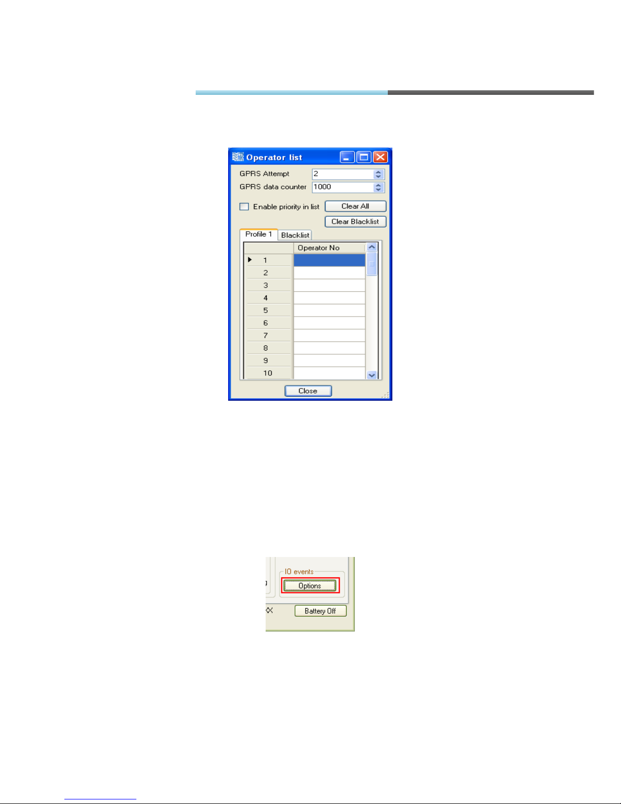
Operator list is placed in the middle right on the main view and is accessible by clicking options
(Fig. 5.3.3.4). In the new opened window you can set up to 50 preferred mobile network operators
for each profile. Operators are added as numbers (up to six digits). If you want to add Afghanistan
AWCC operator, you should enter 41201 (Fig.5.3.3.5). If you want to remove operator, select
operator (by clicking it on the list) and then erase it. Also you can clear all operators from the list
by clicking “Clear All”. You can also click on “Enable priority in list”, so the system will choose
operator, which is above in your list if more than one operator can be chosen. You can also add
operators, which you don’t want to connect in a blacklist.
Fig. 5.3.3.4. Operator list options button
FM Manual
Page 51
© All rights reserved to Ruptela UAB
P a g e |
51
Fig. 5.3.3.5. Operator list view
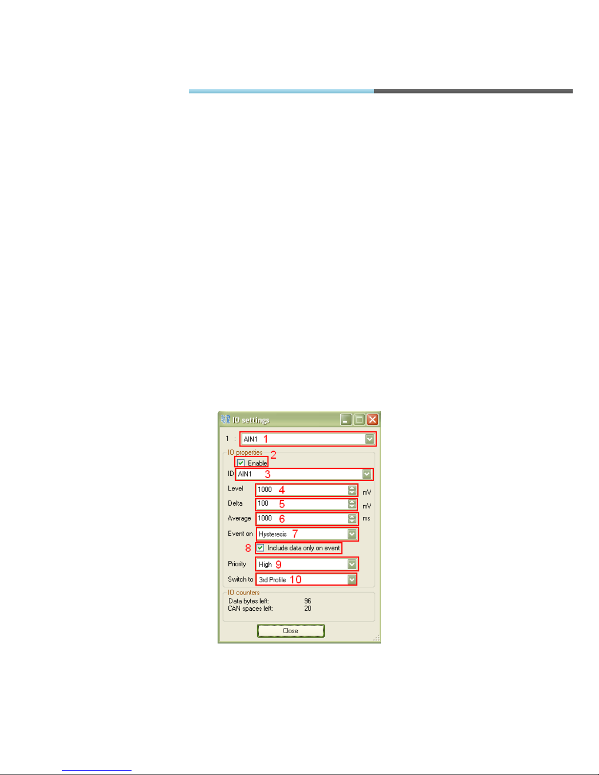
IO events settings are located in the bottom right corner on the main view and are accessible by
clicking “Options” button (Fig. 5.3.3.6). IO is a specific property, which can be measured by FM
device and sent to server. IO event is a reaction to measured value. When IO event occurs, device
makes a record into its memory with measured values, date, time and location. IO events can
initiate GPRS session. Also IO can change device operation (by switching profile). You can select
up to 110 IO events.
Fig. 5.3.3.6. IO events settings buttons
To add IO to data record and create IO event (Fig 5.3.3.7):
• Select space for IO. If it is “Disabled” then it is empty and new IO will be added, otherwise
you will overwrite IO and it will be replaced with new one.
FM Manual
Page 52
© All rights reserved to Ruptela UAB
P a g e |
52
• Check “Enable”.
• Select property ID you want to measure.
• Set “Level” (optional, used for Hysteresis (explained below), IO dependant).
• Set “Delta” (optional, used for Hysteresis (explained below), IO dependant).
• Set “Average” (averaging is used to ensure that IO value is long time result and not short
impulse value). Some parameters, which has static values (like iButton ID) ignores
averaging.
• Select “Event on”(Monitoring – no event generation, only include value to record; Hysteresis
– event generation defined by “Level” and “Delta”; Change – event generated when
measured property changes, that means its value is different from previous registered
value).
• Select whether to always include value to record or only when event is generated.
• Select priority (Low – do not start GPRS session after event and send data according to
timing defined in parameters “Period” and “Timetable”(Fig. 5.3.3.1.), High – start GPRS
session after event and send data if “Timetable” allows GPRS activity at that time).
• Select whether to switch profile on this event or not.
Fig. 5.3.3.7. IO events settings buttons
FM Manual
Page 53
© All rights reserved to Ruptela UAB
P a g e |
53
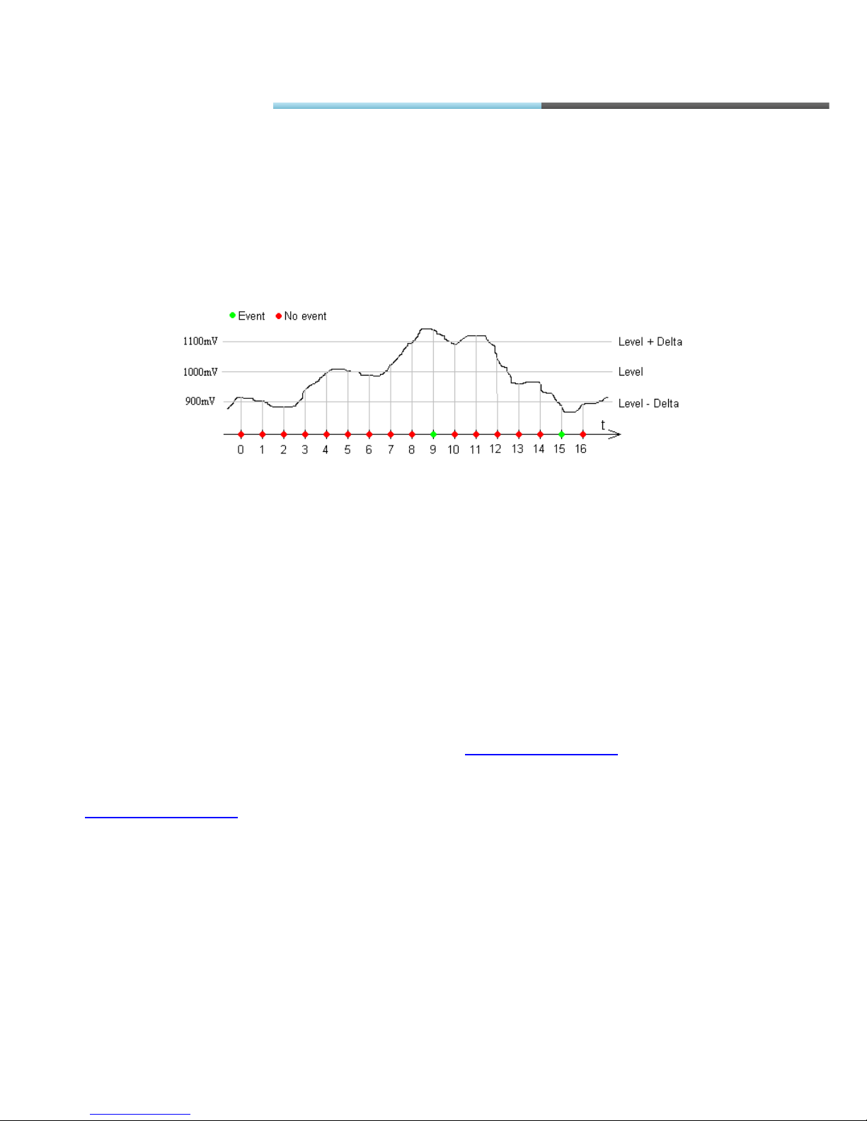
Hysteresis principle is applied to reduce amount of events generated and thus reduce
GPRS traffic. For example, take configuration from Fig. 5.3.3.7: voltage on analogue1 input (AIN1)
will be measured, event will be generated on hysteresis then signal on analogue rises from 1000100=900mV to 1000+100=1100mV, or falls from 1100mV to 900mV, with samples averaged within
1s intervals; data will be included only when event is generated; and when an event is generated,
GPRS session will be initiated and device will switch to 3
rd
profile. To generate event on
“Hysteresis” property value must travel from Level-Delta to Level+Delta or vice versa. In Fig.
5.3.3.8 event will be generated on 9
th
and 15th seconds.
Fig. 5.3.3.8. Hysteresis explanation
Some IO options have conventional parameter measurement units (analogue inputs, temperature
measurements, etc.) while others are defined in specific standards (as CAN FMS 2.0).
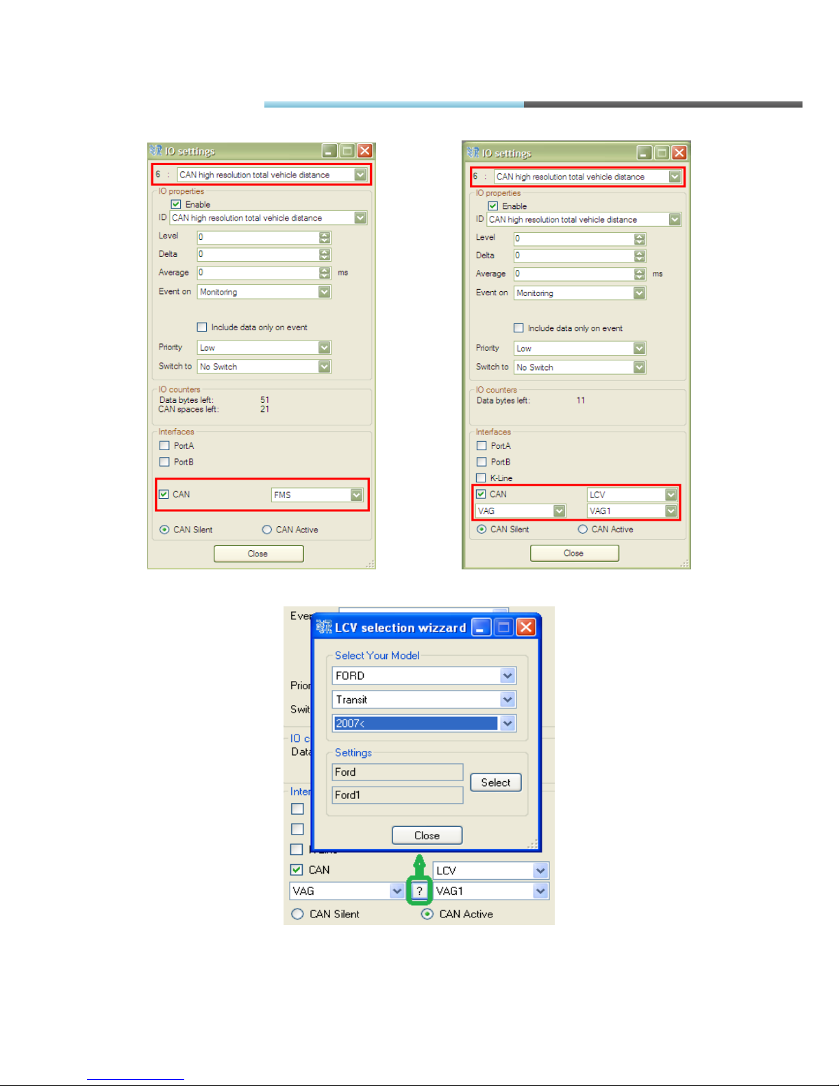
CANbus parameters settings. settings are located in the bottom right corner on the main view
and are accessible by clicking “Options” button (Fig. 5.3.3.6). For different vehicles, different
settings must be used.
Different devices supports different type of CANbus:
PRO3 – supports only FMS standard CANbus;
TCO3 – supports FMS standard CANbus, CANbus OBD, OBD through K-line, light and
commercial vehicles (LCV) CANbus and other types of CANbus. More information about CANbus
supported vehicles, please ask Ruptela support team
upports FMS standard CANbus for light and commercial vehicles (LCV) CANbus and other types
of CANbus. More information about CANbus supported vehicles, please ask Ruptela support team
To set CANbus parameters correctly for PRO3 units, please see an example Fig. 5.3.3.9.
To set CANbus parameters correctly for TCO3 units, please see an example Fig. 5.3.3.10.
FM Manual
Page 54
© All rights reserved to Ruptela UAB
P a g e |
54
Fig. 5.3.3.9. FMS standard CANbus settings Fig. 5.3.3.10. LCV CANbus settings
Fig. 5.3.3.11 LCV CANbus settings
FM Manual
Page 55
© All rights reserved to Ruptela UAB
P a g e |
55
You can also select “?” for help in configuration (fig. 5.3.3.11).
PRO3, TCO3 units can read CANbus from vehicles in Silent and in Active mode.
CAN Silent – means device is not communicating with vehicle Board computer, it only listens for
the data which is on CANbus line.
CAN Active - this type of CAN communication is when our device communicates with Board
computer and sends commands to get one or another CANbus parameter from Board computer.
Mostly this is used when OBD connection is used or some extra (third part) CANbus converter
between vehicle and PRO3,TCO3 devices is connected.
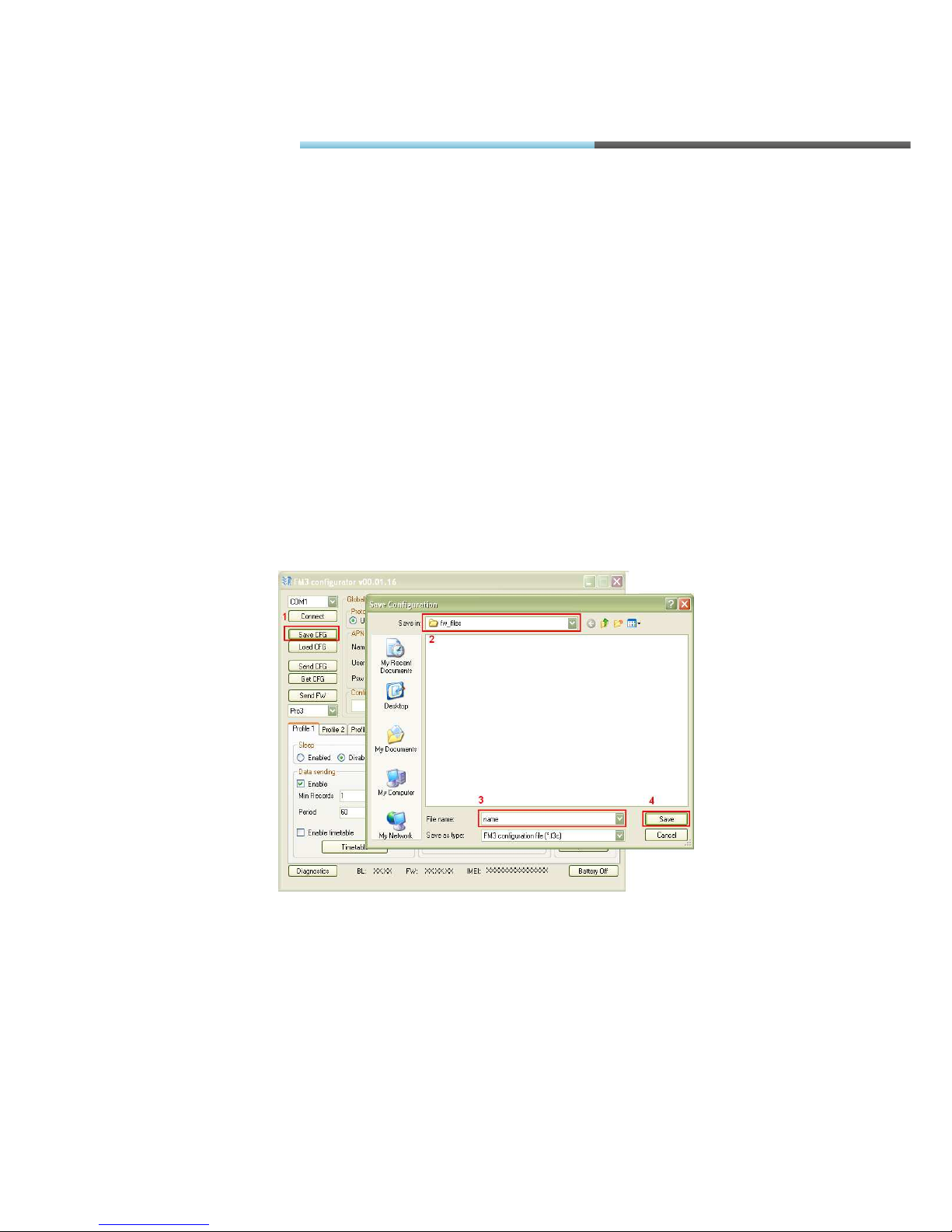
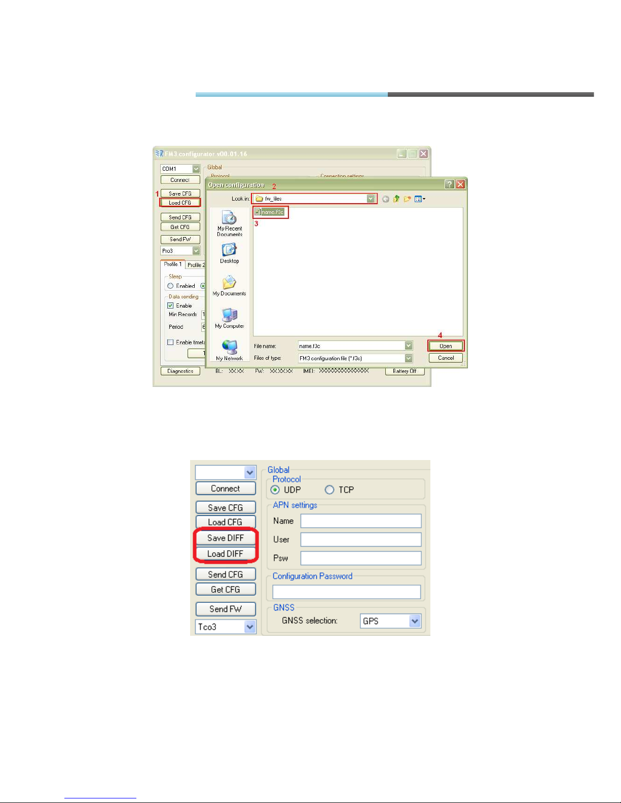
5.3.4. SAVING AND LOADING CONFIGURATION
Fig. 5.3.4.1. Configuration saving scheme
In the main view upper left corner there are “Save CFG” and “Load CFG” buttons, which save and
load configuration files. In order to save file click “Save CFG”, go to folder where to save
configuration, give name to file and click “Save” (Fig. 5.3.4.1). In order to load configuration, click
“Load CFG”, navigate to folder where configuration file is saved, select file and click “Open”.
FM Manual
Page 56
© All rights reserved to Ruptela UAB
P a g e |
56
Fig. 5.3.4.2. Configuration loading scheme
There’s an ability to save and load only a difference in configurations. When loading difference,
new parameters will be applied from loaded configuration (fig. 5.3.4.3).
Fig. 5.3.4.3. Saving and loading differences
FM Manual
Page 57

© All rights reserved to Ruptela UAB
P a g e |
57
Both actions, saving and loading, can be completed whether the device is connected or
disconnected from PC.
Different device types (FM-Eco3, FM-Pro3, FM-Tco3) have slightly different configuration options.
So when configuring without connected device, pay attention to which type is selected (Fig.
5.3.4.2.). Each device type has its own configuration file extension: FM-Eco3 – .fe3c, FM-Pro3 –
.fp3c, FM-Tco3 – .ft3c.
5.3.5. SAVING AND LOADING CONFIGURATION
In the main view upper left corner there are “Send CFG” and “Get CFG” buttons, which are
responsible for configuration exchange with device. These actions can only be performed when
connected to COM port (chapter 5.3.1). In order to get configuration from device click “Get CFG”
button. The controls will be frozen for a while and on the bottom you will see progress bar active.
Analogue actions should be done to send configuration to device. All profiles are saved and
loaded from device at once. Report will be written at the bottom of main view after action.
Possible reports:
• Configuration Sent Successfully
• Configuration Send Error!
• Configuration Received Successfully
• Configuration Receiving Error!
If you receive error report, retry your last action once again. In most cases this should fix the
problem. If you are still having this problem, please contact our support engineers
([email protected])
5.4. FIRMWARE UPDATE
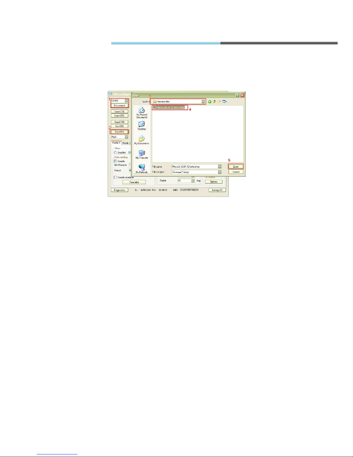
Configurator is also used to update firmware version of FM terminal type device. There is
“Send FW” button (on the middle left on the main view (Fig 5.4.1)), it opens dialogue window to
search for firmware file. Different device type has its own firmware file: FM-Eco3 – .efwe, FM-Pro3
– .efwp, FM-Tco3 – .efwt. User has to open device COM port, click “Send FW”, navigate to
appropriate folder, select file and click “Open” (Fig. 5.4.2).
Fig. 5.4.1. Firmware update button
FM Manual
Page 58
© All rights reserved to Ruptela UAB
P a g e |
58
After sending firmware file to the device, notification will pop up on the bottom of the device and
LEDs will glow continuously for about a minute. Firmware update takes up to 5 minutes, so device
must be powered up during that time. Device is completely ready to use when LEDs start blinking.
Fig. 5.4.2. Firmware update scheme
FM Manual
Page 59
© All rights reserved to Ruptela UAB
P a g e |
59
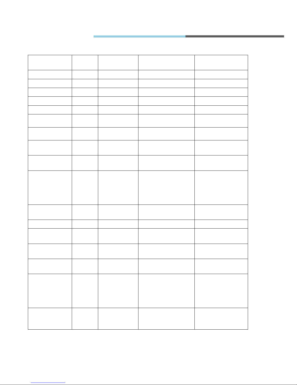
5.5. APPENDIX – IO LIST
IO name
IO size,
B
IO value range
IO value explanation
Notes
AIN1 2 0-65535
mV
AIN2 2 0-65535
mV
Accelerometer X 1 -127...127
Acceleration in X direction 0,05 bitgain
Accelerometer Y 1 -127...127
Acceleration in Y direction 0,05 bitgain
Accelerometer Z 1 -127...127
Acceleration in Z direction 0,05 bitgain
Battery current 2 0-65535
mA
Should not exceed
250mA
Battery Voltage 2 0-65535
mV
Should be between 3300
and 4300mV
CAN accelerator
pedal position 1
1 0-255
0-
100% pressed, by 0,4%
steps
128=51% -
pedal
pressed to the middle
CAN ambient air
temperature
2 0-65535
0.03125 °C/Bit gain
-273 °C offset
9376=20°C
CAN a
t least one
PTO engaged
1 0-3
0=No PTO drive is
engaged
1=At least one PTO drive
is engaged
2=Error
3=Not available
CAN axle
location
1 0-15
Defined in FMS 2.0
standard
CAN axle weight 2 0-65535
0.5 kg / Bit gain 20000=10000kg
CAN brake
switch
1 0-1
0=pedal released
1=pedal pressed
CAN clutch
switch
1 0-1
0=pedal released
1=pedal pressed
CAN cruise
control active
1 0-1
0=switched off
1=switched on
CAN diagnostics
supported
1 0-3
0=diagnostics is not
supported
1=diagnostics is
supported
2=reserved
3=don´t care
CAN engine
coolant
temperature
1 0-255
1°C / Bit gain
-40°C offset
128=88°C
FM Manual
Page 60

© All rights reserved to Ruptela UAB
P a g e |
60
IO name
IO size,
B
IO value range
IO value explanation
Notes
CAN engine
speed
2 0-65535
0.125 rpm / Bit gain 8000=1000rpm
CAN engine
hours
4 0-4294967295
0.05 h / Bit gain 200000=10000h
CAN engine
percent load at
current speed
1 0-125
1%/bit,
0 to 125% op. range
60=60%
CAN engine total
fuel used
4 0-4294967295
0,5 L / Bit gain 20000=10000L
CAN first driver
ID
16 - Driver ID = Card
Number
CAN fuel level1 1 0-255 0,4 % / Bit gain 128=51%
CAN fuel rate 2 0-64255 0.05L/h per bit
0 to 3212,75L/h
600=30L/h
CAN high
resolution
engine total fuel
used
4 0- 4211081215
0.001 L/bit
0 to 4211081,215 L
1000000=1000L
CAN high
resolution total
vehicle distance
4 0-4294967295
5 m/Bit gain 10000=50000m
CAN
instantaneous
fuel economy
2 0-64256 1/512 km/L per b
0 to 125,5 km/L
2560=5km/L
CAN requests
supported
1 0-3 0=request is not
supported
1=request is
supported
2=reserved
3=don´t care
CAN second
driver ID
16 - Driver ID = Card
Number
FM Manual
Page 61

© All rights reserved to Ruptela UAB
P a g e |
61
IO name
IO size,
B
IO value range
IO value explanation
Notes
CAN tacho
driver 1 card
1 0-1 0=Card not present
1=Card present
CAN service
distance
2 0-65535 5 km / Bit gain
-160 635 km offset
32327=1000km
(negative means
service passed)
CAN system
event
1 0-1 0=no tachogr. Event
1=tachogr. Event
CAN SW-
version
supported
4 Defined in FMS 2.0
standard
CAN tacho
direction
indicator
1 0-1 0=Forward
1=Reverse
CAN tacho
driver 1 time
related status
1 0-15 0=normal
1=15 min bef. 4 ½ h
2=4 ½ h reached
3=15 min bef. 9 h
4=9 h reached
5=15 min bef. 16 h
6=16h reached
14=Error
15=not available
CAN tacho
driver 2 card
1 0-1 0=Card not present
1=Card present
CAN tacho
driver 2 time
related status
1 0-15 0=normal
1=15 min bef. 4 ½ h
2=4 ½ h reached
3=15 min bef. 9 h
4=9 h reached
5=15 min bef. 16 h
6=16h reached
14=Error
15=not available
FM Manual
Page 62

© All rights reserved to Ruptela UAB
P a g e |
62
IO name
IO size,
B
IO value range
IO value explanation
Notes
CAN tacho
vehicle
overspeed
1 0-1 0=No overspeed
1=Overspeed
CAN tacho
driver1 working
state
1 0-7 0=Rest
1=Driver available
2=Work
3=Drive
6=Error
7=not available
CAN tacho
driver2 working
state
1 0-7 0=Rest
1=Driver available
2=Work
3=Drive
6=Error
7=not available
CAN tacho
handling
information
1 0-1 0=no handling
information
1=handling
information
CAN tacho
vehicle motion
1 0-1 0=Vehicle motion not
detected
1=vehicle motion
detected
CAN tachograph
performance
1 0-1 0=Normal
performance
1=Performance
analysis
CAN tachograph
vehicle speed
2 0-65535 1/256km/h Bit gain 15360=60km/h
CAN tire location
1 0-15 Defined in FMS 2.0
standard
CAN vehicle ID 24 - Defined in FMS 2.0
standard
FM Manual
Page 63

© All rights reserved to Ruptela UAB
P a g e |
63
IO name
IO size,
B
IO value range
IO value explanation
Notes
CAN wheel
based speed
2 0-65535 1/256km/h Bit gain 15360=60km/h
Current profile 1 0-4 0=default pfile
1=1st profile
2=2nd profile
3=3rd profile
4=4th profile
Digital Fuel
Sensor A1
2 0-1023 Relative to size 1023= full, 0= empty
Digital Fuel
Sensor A2
2 0-1023 Relative to size 1023= full, 0= empty
Digital Fuel
Sensor A3
2 0-1023 Relative to size 1023= full, 0= empty
Digital Fuel
Sensor A4
2 0-1023 Relative to size 1023= full, 0= empty
Digital Fuel
Sensor A5
2 0-1023 Relative to size 1023= full, 0= empty
Digital Fuel
Sensor A6
2 0-1023 Relative to size 1023= full, 0= empty
Digital Fuel
Sensor A7
2 0-1023 Relative to size 1023= full, 0= empty
Digital Fuel
Sensor A8
2 0-1023 Relative to size 1023= full, 0= empty
Digital Fuel
Sensor A9
2 0-1023 Relative to size 1023= full, 0= empty
Digital Fuel
Sensor A10
2 0-1023 Relative to size 1023= full, 0= empty
Digital Fuel
Sensor B
2 0-1023 Relative to size 1023= full, 0= empty
Din1 Hour
counter
4 0-4294967295 Time counter when
Din is in high state in
seconds
FM Manual
Page 64

© All rights reserved to Ruptela UAB
P a g e |
64
IO name
IO size,
B
IO value range
IO value explanation
Notes
Din2 Hour
counter
4 0-4294967295 Time counter when
Din is in high state in
seconds
Din3 Hour
counter
4 0-4294967295 Time counter when
Din is in high state in
seconds
Din4 Hour
counter
4 0-4294967295 Time counter when
Din is in high state in
seconds
DIN1 1 0-1 0=low level on input
1=high level on input
DIN2 1 0-1 0=low level on input
1=high level on input
DIN3 1 0-1 0=low level on input
1=high level on input
ECO brake
counter
1 0-255
Braking event counter
ECO cruise
control timer
4 0-4294967295 Split parameter for
time when cruise
control was on and
cruise control should
be on
ECO engine on
timer
2 0-65535 Time when engine
was on
ECO extreme
and harsh brake
counter
1 0-255 Split counter for
extreme and harsh
braking
ECO idling timer
2 0-65535 Time when engine
was idling
ECO max RPM 2 0-65535 Maximum RPM value
ECO max speed
1 0-255 Maximum speed
value
FM Manual
Page 65
© All rights reserved to Ruptela UAB
P a g e |
65
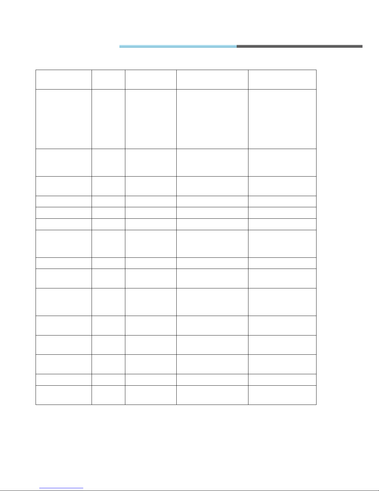
IO name
IO size,
B
IO value ran
ge IO value explanation
Notes
GSM signal level
1 0-31 0=-115dBm or less
1=-111dBm
2...30=-110...-54dBm
31=-52dBm or
greater
99=not known or
detectable
ECO
overspeeding
timer
2 0-65535 Time whed speed
was above limit
ECO RPM in red
band timer
2 0-65535 Time when RPM was
not optimal
Fuel Counter 1 2 0-65535 Depends on Counter
Fuel Counter 2 2 0-65535 Depends on Counter
GPS speed 1 0-255 Value km/h
GSM operator 4 0-4294967295
Unique Mobile
operator code
http://en.wikipedia.or
g/wiki/Mobile_Netwo
rk_Code
iButton ID 8 - Unique iButton ID
Ignition(DIN4) 1 0-1 0=low level on input
1=high level on input
Movement
sensor
1 0-1 0=No motion
detected
1=Motion detected
Modem
temperature
1 -40-90 °C
PCB
temperature
1 -40-80 °C
Power supply
voltage
2 0-65535 mV
TCO distance 4 0-4294967295
5 m/Bit gain 10000=50000m
TCO engine
speed
2 0-65535 0.125 rpm / Bit gain 8000=1000rpm
FM Manual
Page 66

© All rights reserved to Ruptela UAB
P a g e |
66
IO name
IO size,
B
IO value range
IO value explanation
Notes
TCO first
driver card
1 0-1 0=Card not present
1=Card present
TCO first
driver ID
16 - Driver ID = Card
Number
TCO first
driver state
1 0-7 0=Rest
1=Driver available
2=Work
3=Drive
6=Error
7=not available
TCO
registration
number
16 - License plate number
TCO second
driver card
1 0-1 0=Card not present
1=Card present
TCO second
driver ID
16 - Driver ID = Card
Number
TCO second
driver state
1 0-7 0=Rest
1=Driver available
2=Work
3=Drive
6=Error
7=not available
TCO first
driver card
1 0-1 0=Card not present
1=Card present
TCO first
driver ID
16 - Driver ID = Card
Number
TCO first
driver state
1 0-7 0=Rest
1=Driver available
2=Work
3=Drive
6=Error
7=not available
TCO
registration
number
16 - License plate number
TCO second
driver card
1 0-1 0=Card not present
1=Card present
FM Manual
Page 67

© All rights reserved to Ruptela UAB
P a g e |
67
IO name
IO size,
B
IO value range
IO value explanation
Notes
TCO second
driver ID
16 - Driver ID = Card
Number
TCO trip
distance
4 0-4294967295 5 m/Bit gain 10000=50000m
TCO vehicle ID 24 - Defined in FMS 2.0
standard
TCO vehicle
speed
2 0-65535 1/256km/h Bit gain 15360=60km/h
Temperature
sensor0
2 -550-1250 0,1 °C / Bit gain 200=20°C
2001 – 1wire bus
short-circuit
2002 – CRC error
2003 – no sensors
2004 – abnormal
temperature
Temperature
sensor0 ID
8 - Unique temperature
sensor ID
Temperature
sensor1
2 -550-1250 0,1 °C / Bit gain 200=20°C
2001 – 1wire bus
short-circuit
2002 – CRC error
2003 – no sensors
2004 – abnormal
temperature
Temperature
sensor1 ID
8 - Unique temperature
sensor ID
Temperature
sensor2
2 -550-1250 0,1 °C / Bit gain 200=20°C
2001 – 1wire bus
short-circuit
2002 – CRC error
2003 – no sensors
2004 – abnormal
temperature
Temperature
sensor2 ID
8 - Unique temperature
sensor ID
Virtual odometer
4 0-4294967295 m
FM Manual
 Loading...