

Page 1
Page 2

Table of contents
1 Preface ......................................................................................................................................... 2
1.1 Use of this document .............................................................................................................. 2
1.2 Document change log ............................................................................................................. 2
2 Introduction .................................................................................................................................. 3
2.1 Purpose ................................................................................................................................. 3
2.2 Acronyms ............................................................................................................................... 3
2.3 Legal information .................................................................................................................... 3
2.4 Safety .................................................................................................................................... 3
2.5 References ............................................................................................................................. 4
3 Device description ......................................................................................................................... 6
3.1 About .................................................................................................................................... 6
3.2 Package contents ................................................................................................................... 6
3.3 Physical characteristics ............................................................................................................ 7
3.4 Technical characteristics .......................................................................................................... 7
3.5 IO pin out .............................................................................................................................. 8
3.6 Interfaces and peripheral accessories ..................................................................................... 10
3.7 Certification .......................................................................................................................... 11
3.8 LED status ........................................................................................................................... 11
3.8.1 GNSS LED ..................................................................................................................... 11
3.8.2 GSM LED ....................................................................................................................... 11
3.8.3 Peripheral LED ............................................................................................................... 12
3.8.4 LED status in sleep and deep sleep modes ....................................................................... 13
4 Device configuration .................................................................................................................... 14
4.1 Driver installation.................................................................................................................. 14
4.2 Sample configuration ............................................................................................................ 16
4.3 Advanced configuration ......................................................................................................... 18
4.3.1 Global settings ............................................................................................................... 19
4.3.2 Profile settings ............................................................................................................... 24
4.3.3 IO settings .................................................................................................................... 29
4.4 Integration protocol .............................................................................................................. 35
5 Installation recommendations ....................................................................................................... 36
5.1 Device installation ................................................................................................................. 36
5.2 FM-Pro4 BT device ................................................................................................................ 36
5.3 Antenna installation .............................................................................................................. 36
Page 3
Date
Version
Change details
2016-06-16
1.0
Initial draft
2016-08-30
1.1
Added FW and FM4 configurator compatibility check description in
“Advanced configuration” chapter. Added “Shock detection” description in
“Global settings” chapter.
2016-10-14
1.2
Added “CAN HCV” and “DXP CAN” modes descriptions in the “IO settings”
chapter.
2016-11-29
1.3
Information about FM-Pro4 BT device in “Technical characteristics”, “Global
settings” and “Installation recommendations” chapters.
2016-12-13
1.4
“Constant TCP link” functionality description in “Profile settings” chapter.
2017-01-30
1.5
In the “IO settings” chapter: CANbus data filter by engine sate described.
“Keep TCO parameter values when engine is OFF” described.
2017-03-09
1.6
Changed DIFF file description in “Advanced Configuration” chapter.
1 Preface
1.1 Use of this document
This document provides required information for proper device handling, preparation, configuration and
installation to a vehicle. This document has a linear structure – from the device package box reception to
the recommendations on how to install the device to the vehicle. However it is not overfilled with
unnecessary information. You will find only basic descriptions about various functions and actions needed
to start using the device. Additionally, there will be references to a more detailed descriptions.
The following markings are used to highlight important information:
Notes contain important information that you need to pay attention to.
Note
Notes like this contain important information!
Actions and various elements of the software required for configuration of the device are marked
in bold.
All actions are described in sequence in the following five sections: Introduction, Device
description, Device preparation, Device configuration and Installation recommendations.
1.2 Document change log
Page 4
All the associated (additional) equipment such as PC’s, batteries, sensors etc., shall meet the
requirements of standard EN60950-1.
Do not disassemble the terminal. If the enclosure of the terminal is damaged, or the insulation of
wires is damaged, first of all disconnect power supply cables from power supply source.
All of the wireless data transferring equipment produces interference that may affect other
devices, which are placed nearby.
The terminal can be installed or dismounted only by qualified personnel!
The terminal must be firmly fastened in the predefined location. Predefined location is described
in the mounting instructions.
The programming must be performed using a 2nd safety class PCs (with an autonomic power
supply).
2 Introduction
2.1 Purpose
The purpose of this document is to provide physical and technical data of the device, to explain device’s
behavior and how various conditions are indicated. Device preparation for the operation and its
configuration instructions are included as well.
2.2 Acronyms
PC – Personal Computer;
GPRS – General Packet Radio Service;
GPS – Global Positioning System;
GSM – Global System for Mobile Communications;
GLONASS – Global Navigation Satellite System;
GNSS – Global Navigation Satellite System;
SMS – Short Message Service;
AC / DC – Alternating Current/Direct Current;
PCB – Printed Circuit Board;
LED – Light Emitting Diode;
I / O – Inputs / Outputs;
2G – second generation of mobile telecommunications technology;
3G – third generation of mobile telecommunications technology;
UMTS – Universal Mobile Telecommunications System;
BT - Bluetooth
2.3 Legal information
Copyright © 2016 Ruptela. All rights reserved. Reproduction, transfer, distribution or storage of parts or all
of the contents in this document in any form without the prior written permission of Ruptela is prohibited.
Other products and company names mentioned in this document are trademarks or trade names of their
respective owners.
2.4 Safety
Page 5
Make sure that the terminal is installed in a place, where it will not be subjected to harsh
environmental conditions for extended time periods.
Caution! If an incorrect type of battery is used for replacement, there is a high explosion risk.
Dispose used batteries according to the environmental requirements.
Any installation and/or handling during a lightning storm is prohibited.
For configuration use cables that were purchased from Ruptela. Ruptela is not responsible for
any harm caused, while using wrong cables for the PC ↔ Terminal connection.
Attention! Do not connect the wires marked red (power supply) and black (chassis) to the wrong
battery poles. Device has a reverse polarity protection, however if connected incorrectly, the
device will not work
To disconnect the device from the power supply, you need to disconnect 12 PINs plug from the
device or disconnect the wires from the vehicle‘s power supply.
This crossed-out wheelie bin symbol means that waste equipment should not be disposed of with
your other household waste. The product must be taken to separate collection points at the
product`s end-of life.
This chapter contains procedures to help you safely operate the FM terminal. By following these
requirements and recommendations, you will avoid dangerous situations. You must read these instructions
carefully and follow them strictly before operating the device! The terminal is supplied from a car battery
with these ratings: 12/24 V DC. The allowed voltage range from the battery is from 10 volts to 32 volts DC.
Max. current for FM-Pro4 is 250 mA @ 12 V DC. Max. current for FM-Pro4 3G / Pro4 BT is 350 mA @ 12 V
DC.
To avoid mechanical damage, it is advised to transport the FM terminal in an impact-proof package.
Before connecting wires of the 12 PIN cable to the vehicle, it is recommended to ensure that the crosssectional area of wires mounting is at least 0.75 mm2.
To correctly dismount the terminal from the vehicle, first of all disconnect power supply wires (12 PIN
connector). Only then other plugs or interfaces can be disconnected.
The terminal is intended to be installed in a restricted access location, which is not accessible for the
operator.
2.5 References
This document is designed to work in a conjunction with other documents. Documentation is kept light,
unnecessary information is omitted. Additional and extensive explanations can be found in the
documentation referenced below:
FM-Pro4 / Pro4 3G / Pro4 BT Datasheets – Contains technical data of the FM-Pro4 / Pro4 3G / Pro4
BT device. Datasheets can be acquired from [email protected]
Quick start guide – A quick guide for a better understanding of the device configuration process and
functions.
Peripheral accessories – Instructions on how to use peripheral accessories together with the FM-
Pro4 / Pro4 3G / Pro4 BT device.
Website – Our documentation website that contains the most recent firmware, configurator and
sample configuration files.
Page 6

Microsoft Framework – This additional software is required in order to run our configurator.
VCOM drivers – Drivers required for device connection to PC.
All links are also provided in corresponding sections, where additional information might be needed.
Note
Ruptela documentation website address: doc.ruptela.lt
Page 7
3 Device description
3.1 About
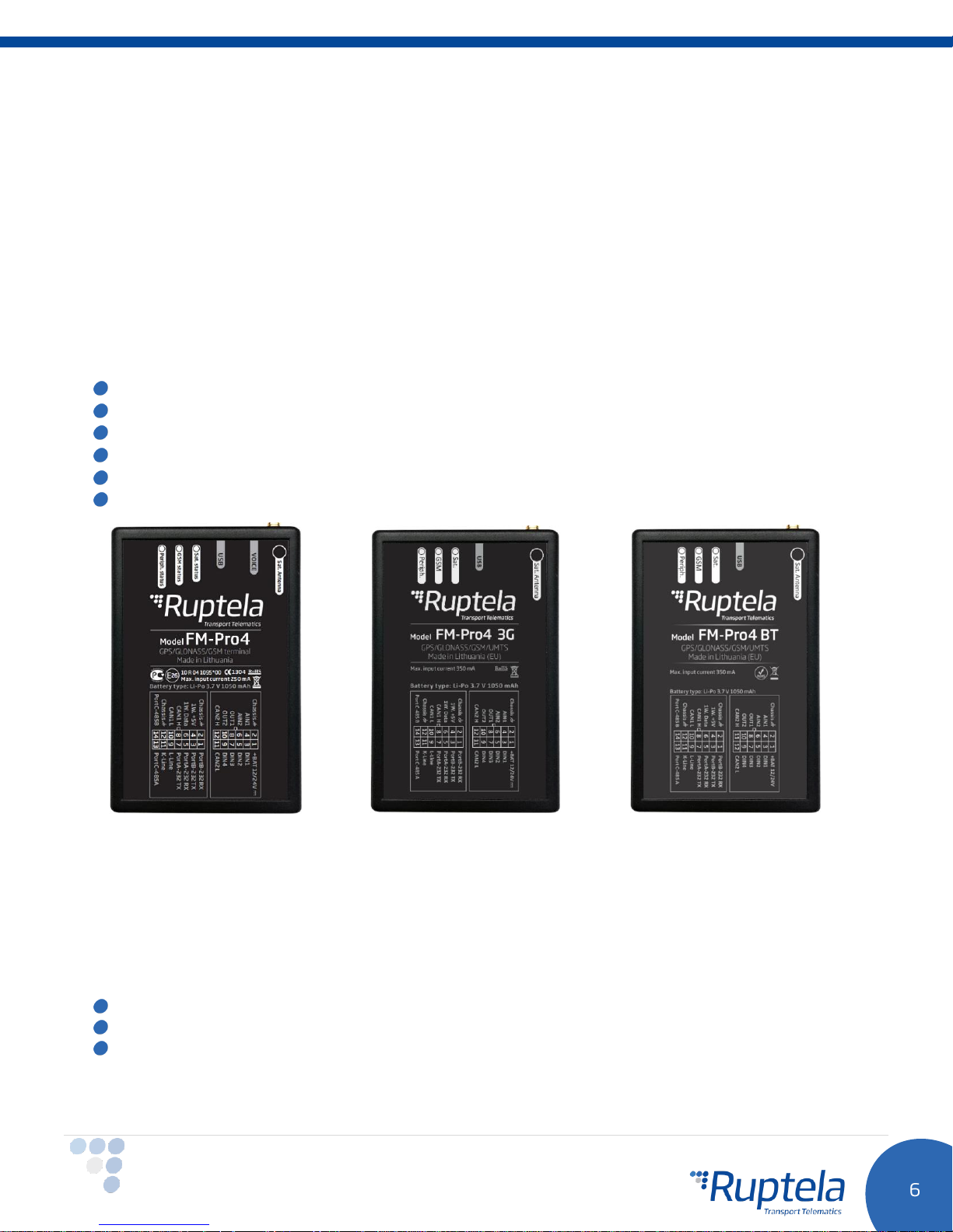
Ruptela‘s FM-Pro4 / Pro4 3G / Pro4 BT is 4th generation advanced, low power consumption but powerful
tracking device. It acquires it’s position by a GPS/GLONASS signal and transfers data to a server via cellular
3G or GSM/GPRS network.
3G network support was not previously available for FM4 devices. This new feature in FM-Pro4 3G is the
main advantage over the FM-Pro4 devices.
FM-Pro4 BT device contains Bluetooth module. This feature further extends its accessories list and adds
new configuration capabilities.
Some common FM-Pro4 / Pro4 3G / Pro4 BT advantages over previous generation FM-Pro3 devices:
Lower power consumption
More powerful 1-wire interface
USB power supply for configuration
2 x RS232 and 1 x RS485 ports work at the same time
2 SIM card slots (on demand, only for FM-Pro4 / Pro4 BT)
Gyroscope (on demand)
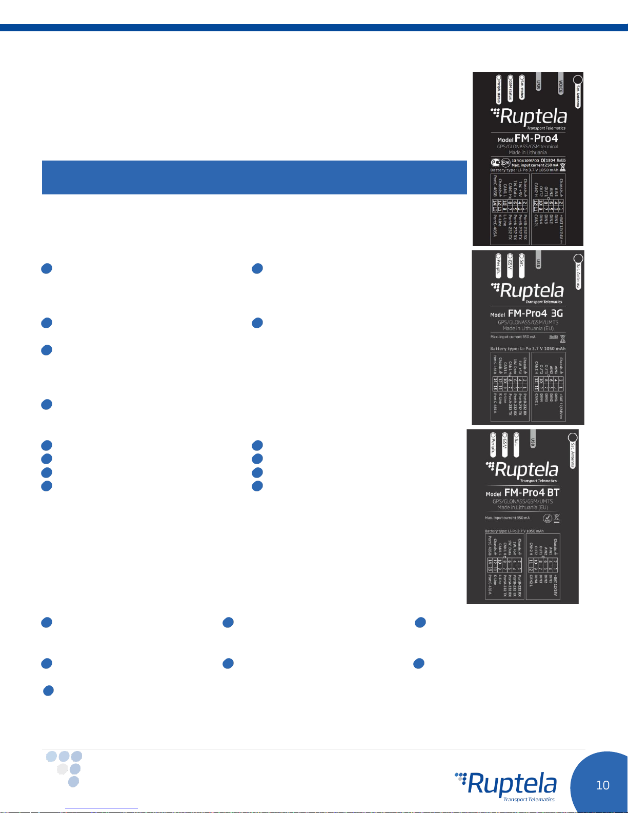
FM-Pro4 FM-Pro4 3G FM-Pro4 BT
3.2 Package contents
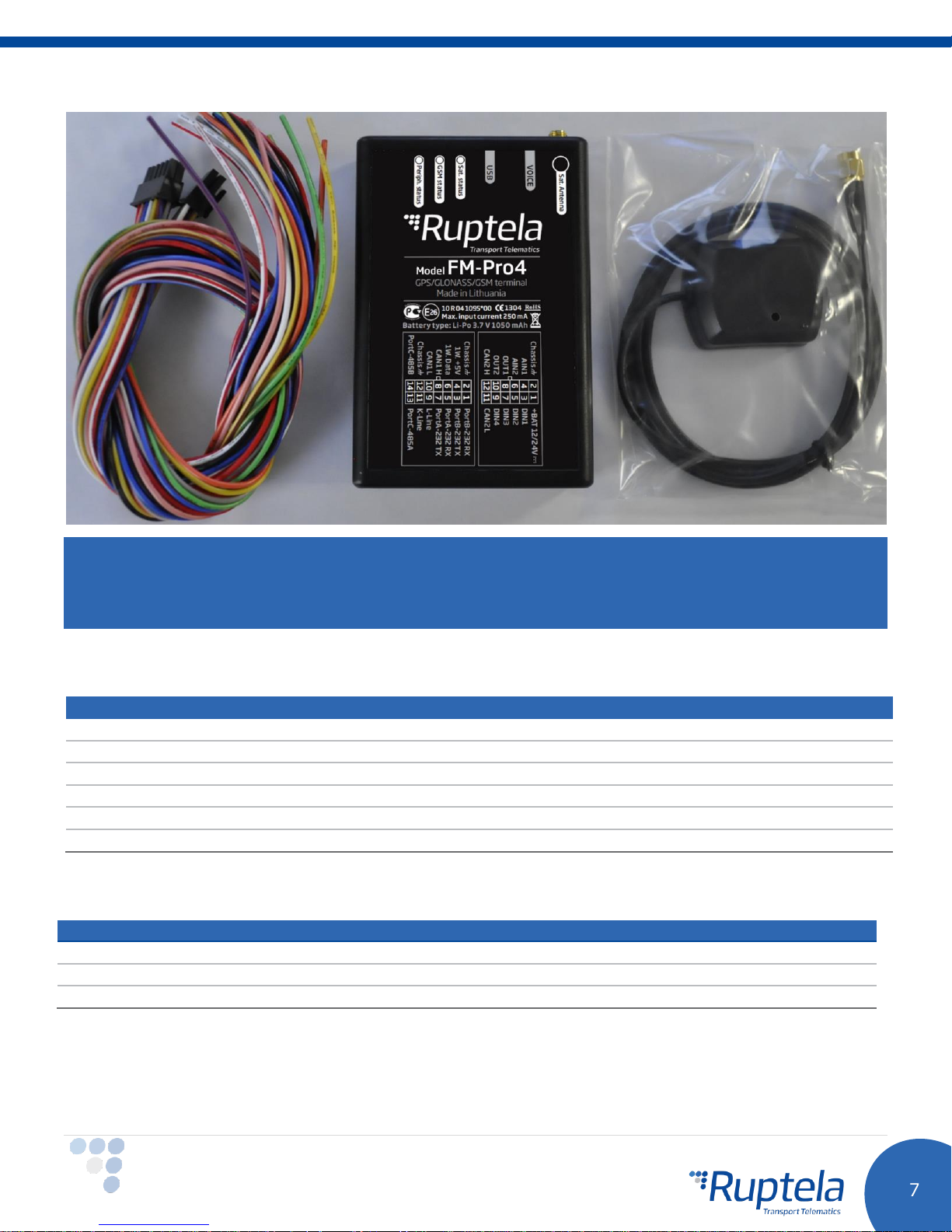
FM-Pro4 / Pro4 3G / Pro4 BT device is supplied in cardboard package. GPS/GLONASS antenna and IO
cables are disconnected from device. Package contents:
FM- Pro4 / Pro4 3G / Pro4 BT device
12 PINs and 14 PINs cables
GPS/GLONASS all-in-one antenna
Page 8
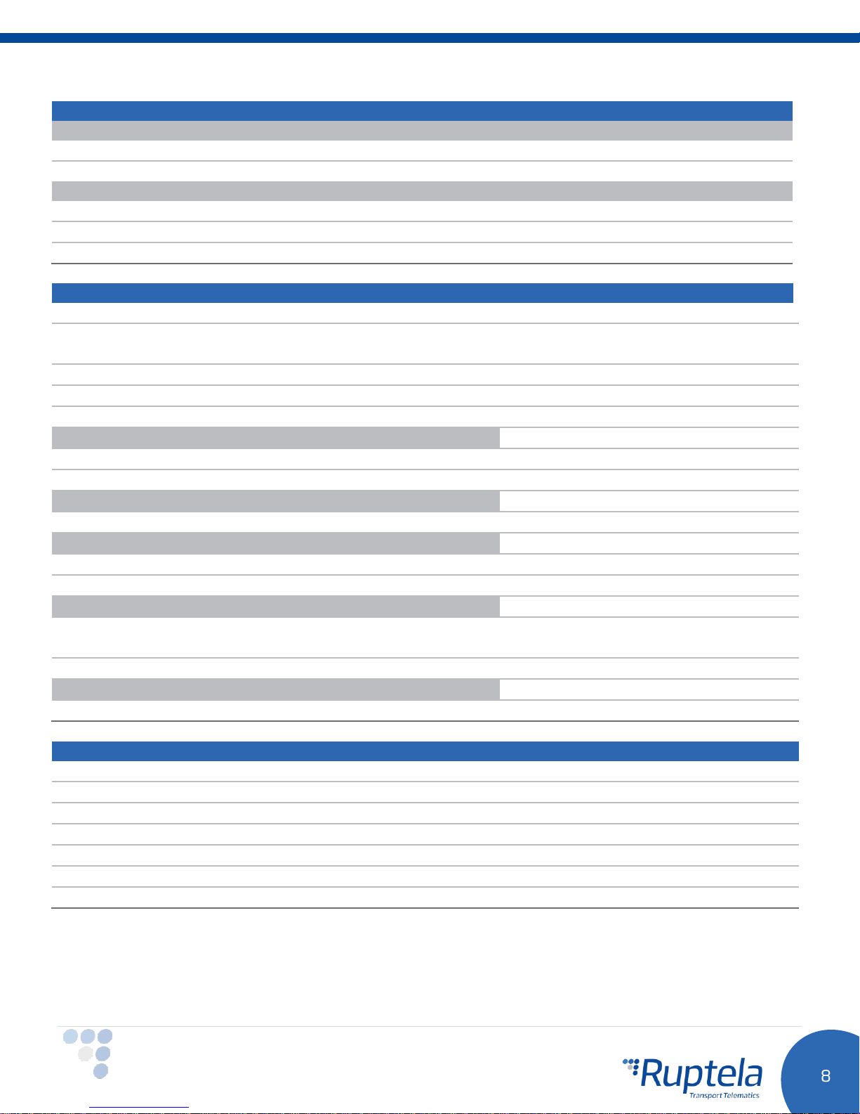
Properties
Enclosure dimensions
111 x 75 x 25 mm
Indication
3 LEDs: Sat. status, GSM status, Periph. status
Housing
Plastic
External elements
GPS/GLONASS all-in-one antenna
Configuration interface
USB
Connectors
12 & 14 PINs
1
Power consumption @ 12V
FM-Pro4
FM-Pro4 BT
FM-Pro4 3G
50
60
70
180
210
150
22
22
22
Note
Providing a SIM card is optional, according to your payment plan. The SIM card is necessary for connection
to the GSM network. The SIM card can be obtained from your local GSM service provider. The SIM card can
work with the terminal only when all SIM card security codes are disabled.
3.3 Physical characteristics
3.4 Technical characteristics
Page 9
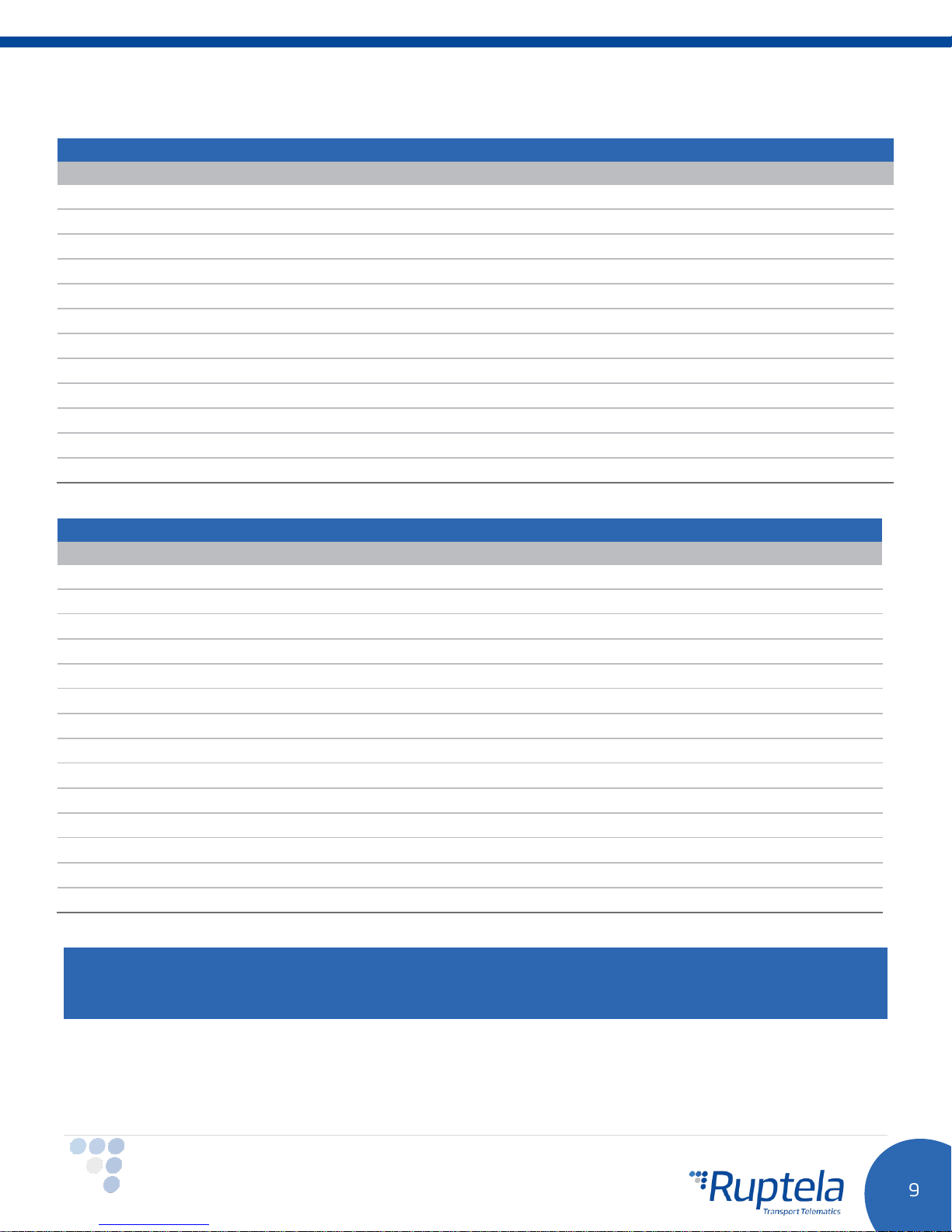
Temperature range for device (without battery)
Storage temperature, °C
-40 ~ +70
Operating temperature, °C
-35 ~ +70
2
Temperature range for battery
Charge, °C
0 ~ +45
Discharge, °C
-20 ~ +60
Storage, °C
-20 ~ +70
Electrical and internal elements 10-32 V DC
50 V @ 60 s
72 V @ 0.1 s
Internal power supply
Li-Po 3.7 V, 1050 mA
Digital input threshold
4 V
Analogue input resolution
12 bit
GPS/GLONASS module
Ublox EVA-M8M
Channels
72
Sensitivity
-163 dBm
GPS/GLONASS antenna
External
Frequency
1575.42 ± 3 MHz
GSM modem
Quectel M95
Bands
850/900/1800/1900 MHz @ GSM
GSM antenna
Internal, Quad band
3
GSM/UMTS modem
Quectel UG96
Bands
800/850/900/1900/2100 MHz @ UMTS
850/900/1800/1900 MHz @ GSM
GSM/UMTS antenna
Internal, Quad band
4
Bluetooth
Bluetooth LOW Energy 4.0
Protections
Short circuit protection
Reverse polarity protection
Electrostatic discharge protection on USB
Electrostatic discharge protection on 1-wire
Overcurrent protection on 1-wire power
3
ESD protection on SIM card slot
5
Charging protection
1
Firmware dependent; given values are valid when there are no peripheral devices attached. If battery is in charging mode, then power consumption in each mode will
be higher within 170 mA.
2
If temp is >45C, charging is disabled, if >60C battery is disconnected from the system at all.
3
Only for the FM-Pro4 3G device.
4
Only for the FM-Pro4 BT device. Feature is currently under development.
5
Not soldered in standard version. Can be ordered.
Page 10
12 PIN connector
Pin nr
Pin
Wire color
Description
1
10-32 V
Red
Power supply 12/24 V (range: 10-32 V)
2
Chassis
Black
Ground connection
3
DIN1
Pink
Digital input, threshold 4 V
4
AIN1
Gray
Analogue input (range: 0-30 V)
5
DIN2
Blue
Digital input, threshold 4 V
6
AIN2
Green
Analogue input (range: 0-30 V)
7
DIN3
White
Digital input, threshold 4 V
8
DOUT1
Purple
Digital output open collector up to 32 V, 1 A
9
DIN4
Yellow
Digital input, threshold 4 V
10
DOUT2
Orange
Digital output open collector up to 32 V, 1 A
11
CAN2 L
Blue/red
J1939 CAN interface low connection
12
CAN2 H
White/red
J1939 CAN interface high connection
14 PIN connector
Pin nr
Pin
Wire color
Description
1
PortB-232 RX
Yellow
RS 232 port B receive signal
2
Chassis
Black
Ground connection
3
PortB-232 TX
Orange
RS 232 port B transit signal
4
1W. +5V
Red
1-wire power supply +5 V, 200 mA
5
PortA-232 RX
Purple
RS 232 port A receive signal
6
1W. Data
Green/yellow
1-wire data channel
7
PortA-232 TX
Pink
RS 232 port A transit signal
8
CAN1 H
White
J1939 CAN interface high connection
9
L-Line
Green
J1939 CAN interface L line channel, diagnostics
10
CAN1 L
Blue
J1939 CAN interface low connection
11
K-Line
Brown
J1939 CAN interface K line channel, diagnostics
12
Chassis
Black
Ground connection
13
PortC-485 A
White/red
RS 485 differential signaling line A
14
PortC-485 B
Yellow/brown
RS 485 differential signaling line B
3.5 IO pin out
Note
Only one CAN line work at the same time. Connect your hardware to one of the interfaces and configure it
accordingly.
Page 11
Available on 1-Wire:
4 × Temperature sensors
DS18B20/DS18S20 (10 mA @ 5 V)
1 × iButton DS1990, DS1971
with passive socket.
Available on DOUTs:
1 × ECO Driving panel (Power
supply from 1-Wire. 40 mA @ 5 V)
1 × Buzzer/LED
1 × Ignition lock (including ignition
block upon GSM jamming detection)
Available on AINs:
2 × Analogue fuel sensors
Available on RS232 ports A and/or B:
2 x LLS digital fuel sensors
Transparent channel
2 x RFID readers
1 x Magnetic card reader
1 x TCO driver card reader
1 x Alcohol sensor
1 x Garmin (Send and receive SMS,
routes to/from navigation system.
(Only on port B)
1 x Spreader
Available on RS485 port C:
Up to 10 LLS fuel sensors
1 x J1708 interface
Transparent channel
Available on CAN interface:
Vehicle CANbus (FMS)
information reading
HCV CAN (heavy commercial
vehicles)
MobilEye
DXP CAN
3.6 Interfaces and peripheral accessories
There are several peripheral accessories that can be connected to the FM-Pro4 /
Pro4 3G / Pro4 BT device. With peripherals you can get even more features and
extended functionality. All available peripherals can be purchased from Ruptela.
Please contact your manager for more details.
Note
Maximum 1-Wire interface power output is 200 mA @ 5 V.
FM-Pro4 / Pro4 3G / Pro4 BT device support RS232, RS485, 1-wire and CAN
interfaces. List of available peripherals devices that can be to them:
Page 12
Certification
FM-Pro4
FM-Pro4 BT
FM-Pro4 3G
E-mark
CE 1304
RoHS
FCC Part 15
Note
Few hardware features that are present in FM-Pro4 are currently not available in FM-Pro4 3G. These
features are 2nd SIM card slot and 3,5 mm TTRS audio interface.
Only FM-Pro4 BT devices have built in Bluetooth module.
You can find peripheral accessories installation instructions and documentation on our documentation
website.
3.7 Certification
FM-Pro4 / Pro4 3G / Pro4 BT devices have passed quality tests and comply with following certifications:
3.8 LED status
3.8.1 GNSS LED
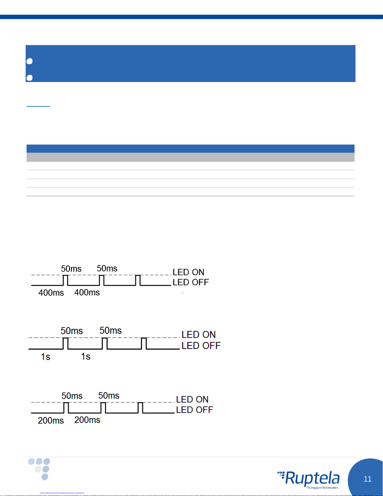
When GPS/GLONASS signal is not received or GPS/GLONASS signal is not accurate, the GPS LED is blinking
as follows:
When accurate GPS/GLONASS signal is received, the GPS LED is blinking as follows:
3.8.2 GSM LED
When GSM signal is not received, GSM LED is blinking as follows:
Page 13
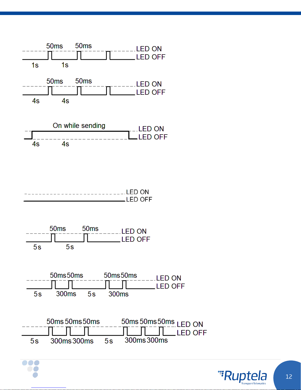
When device has a good GSM signal, but no GPRS, LED is blinking as follows:
When device has good GSM signal and it is connected to GPRS, then LED is blinking as follows:
When the device terminal has GSM signal and it is sending data via GPRS, LED is blinking:
3.8.3 Peripheral LED
The device terminal can have up to 3 peripheral devices attached to it (e.g. CAN, LLS, 1-wire). So there are
4 different types of LED states possible. When there is no peripheral attached, LED will not blink at all:
When there is 1 peripheral interface connected, the peripheral LED is blinking:
When there are 2 peripheral interfaces connected, the peripheral LED is blinking:
When there are 3 peripheral interfaces connected, the peripheral LED is blinking:
Page 14
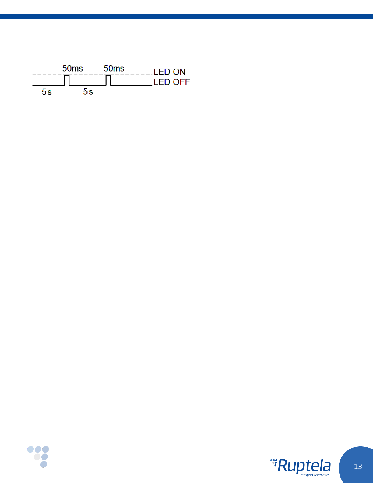
3.8.4 LED status in sleep and deep sleep modes
When device is in sleep / deep sleep mode all three LEDs blink at the same time in the following pattern:
Page 15
4 Device configuration
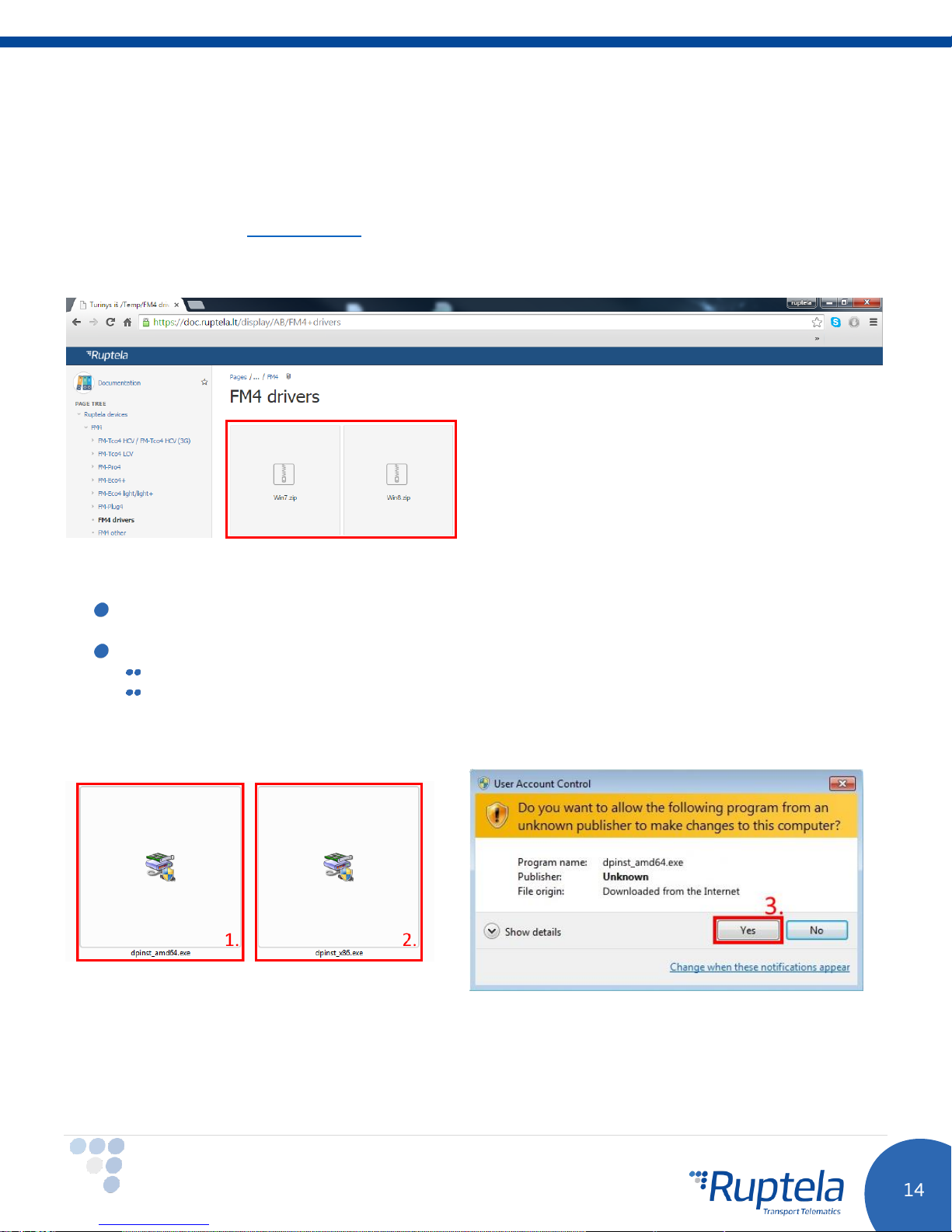
4.1 Driver installation
Virtual COM port driver installation is mandatory, only then your PC will recognize the FM-Pro4 / Pro4 3G /
Pro4 BT device that was connected to the USB port. You can download newest drivers on our
documentation website (VCOM drivers).
Choose correct archive file with drivers for your OS version and download it to your PC.
Installation procedure:
Uninstall previous Virtual COM port driver versions (Start-> Settings-> Control Panel-> Add or
remove programs).
Extract archive file “Win7.zip” or “Win8.zip” to a desired location on your PC.
If you are running a 32-bits OS version, launch the “dpinst_x86.exe” [1.]
If you are running a 64-bits OS version, launch the “dpinst_amd64.exe” [2.]
Windows 7 Users might get a Security Warning message. Click “Yes” [3.].
In the next window select “Next” [4.].
Page 16
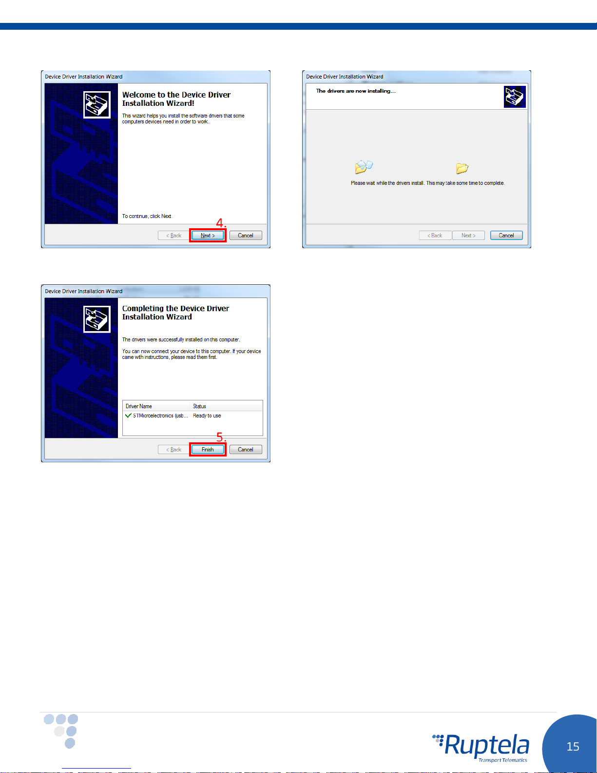
Wait for the setup to complete the installation and click “Finish” [5.].
Driver is now installed and ready to use.
Page 17
4.2 Sample configuration
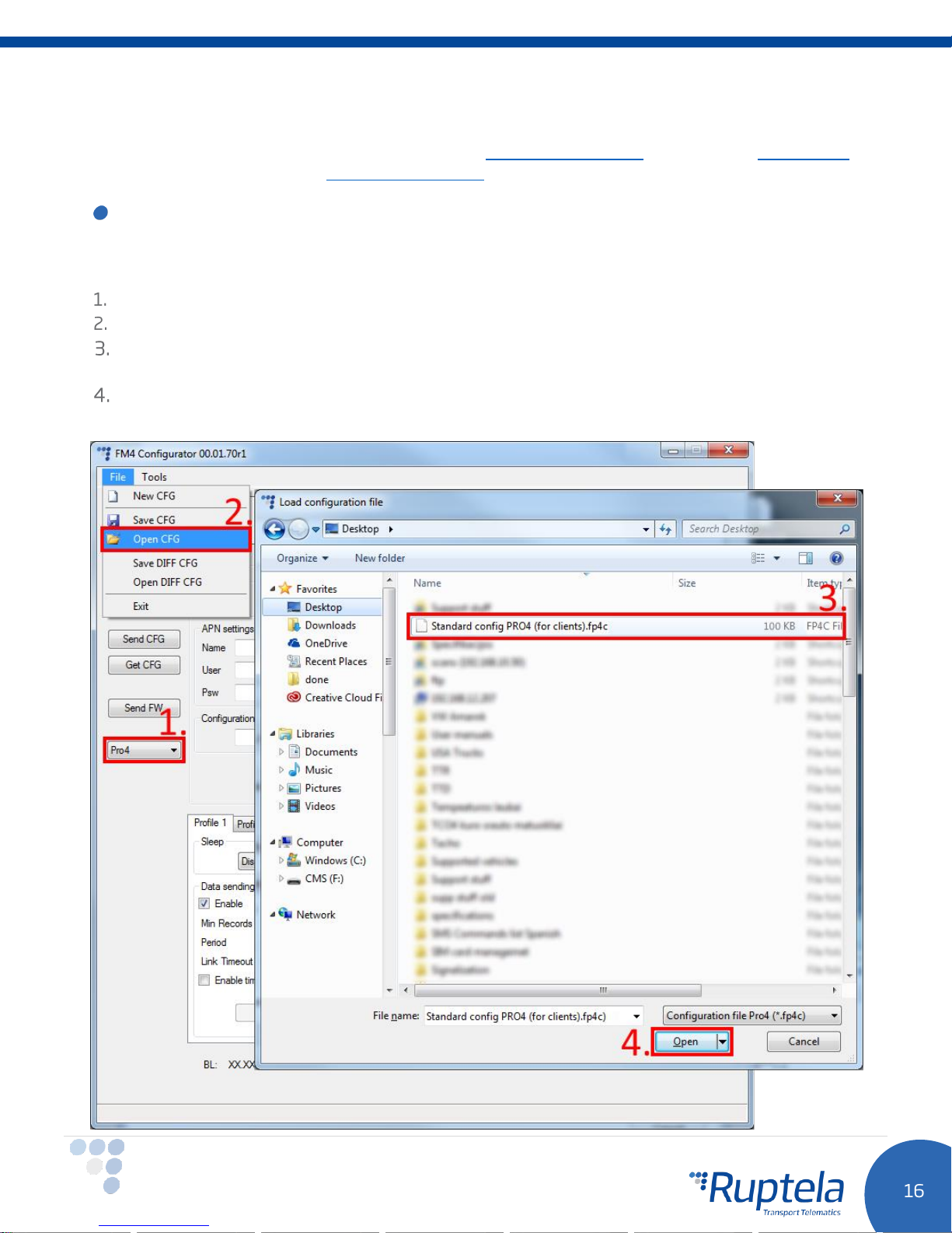
Please go to our documentation website and download sample configuration and the latest configurator. Also
you will need the latest version of Microsoft Framework.
Operating system requirements:
MS Windows XP/Vista/7/8
Example for FM-Pro4 / Pro4 3G:
Start the VCP.exe from configurator folder.
Select Pro4.
Click File → Open CFG.
In dialog window, browse the sample configuration file you downloaded from the documentation
website.
Click Open.
Page 18
FM-Pro4 BT
Procedure for Pro4 BT device is very similar. Download configurator and sample configuration file for the
FM-Pro4 BT device. In configurator select Pro4 BT and open “Standard config PRO BT (for clients).ff4c” file.
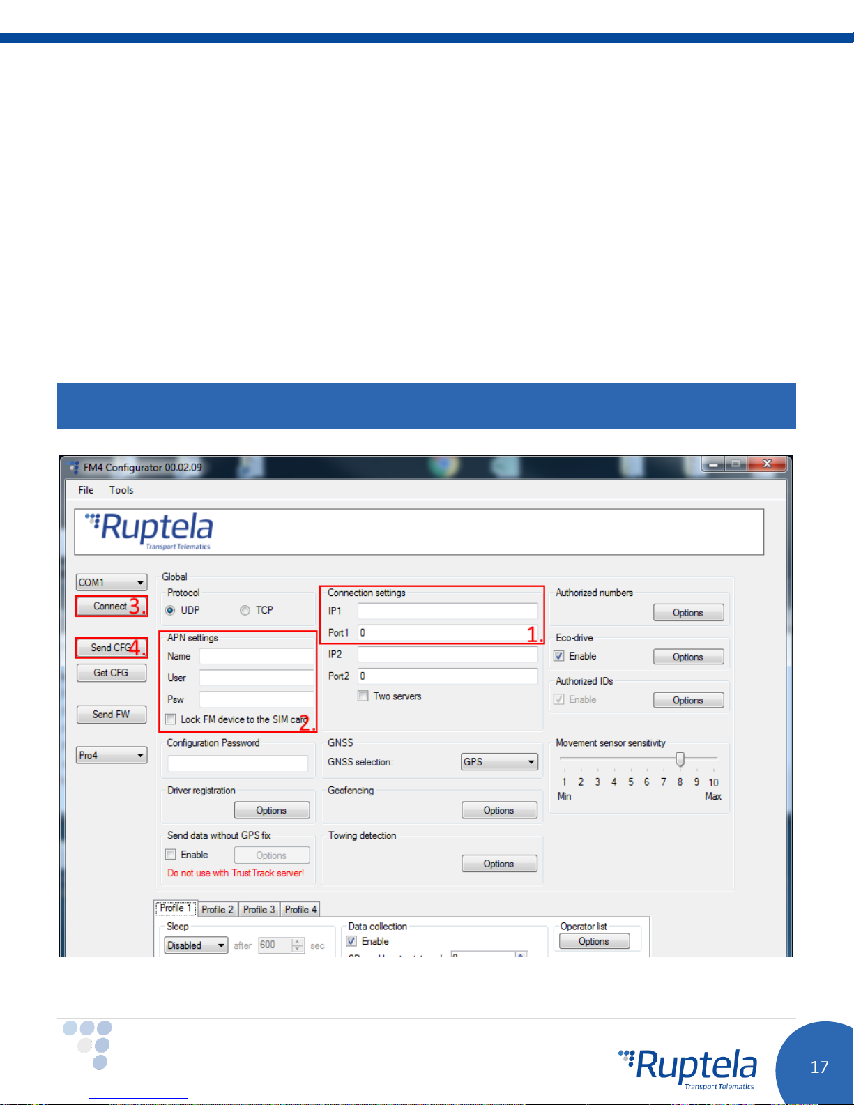
Sample parameters will be loaded. However you will need to enter other parameters on your own.
1. Enter IP (in the 255.255.255.255 format) or a Domain Name (not exceeding 40 characters) and
PORT to which the device should send data.
2. Enter APN settings: APN name, User login and Password (if login and password is needed). If you
choose to enable Lock FM device to the SIM card check-box you will be required to enter SIM
card’s PIN code every time you try to connect to the device via USB cable. As long as it is checked
you will not be able to use different SIM cards with this device.
3. Select a COM port you connected the device to and click “Connect”. At this point the configuration is
ready to be send to the device, so the device must be connected to the computer.
4. Click “Send CFG” button. The configuration will be uploaded to the device.
Note
APN name, login and password should be provided by your mobile network operator.
Now the device is configured to send data to the specific server. Sample IO parameters are enabled
(loaded with configuration file). You can log in to your tracking platform to see whether the device is
sending data.
Page 19
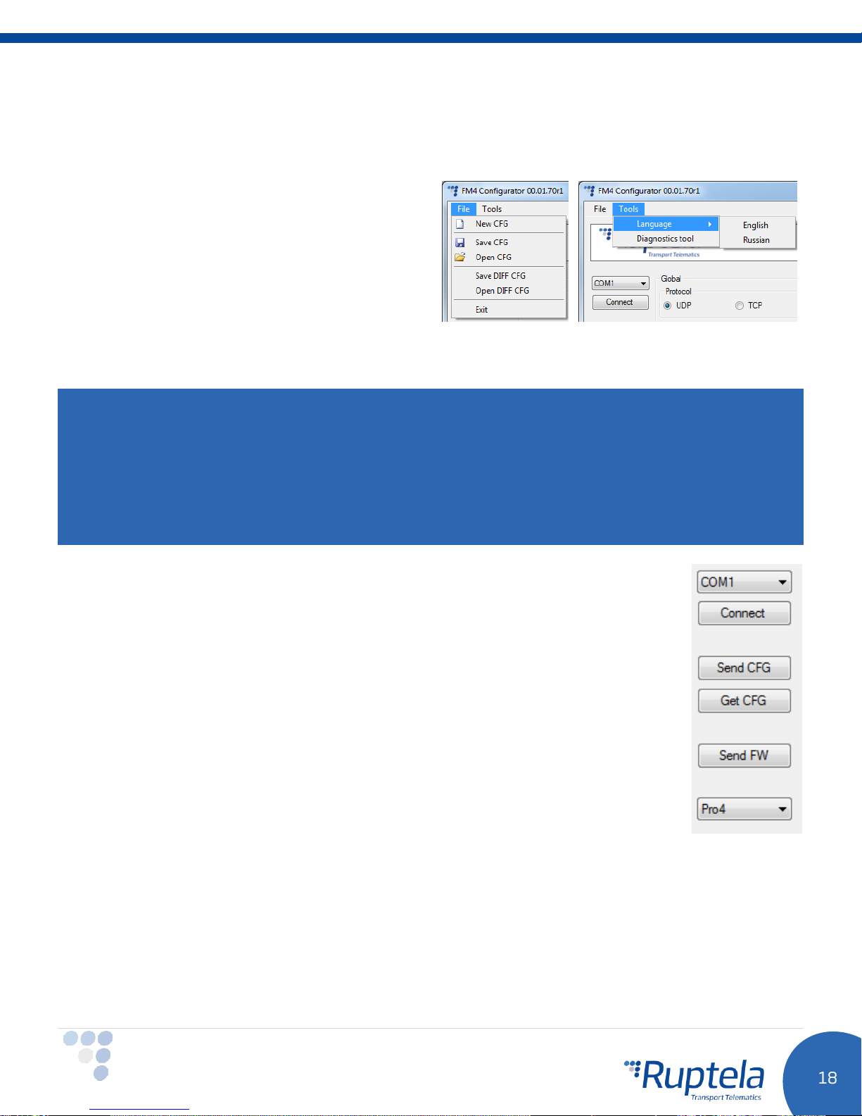
4.3 Advanced configuration
The configuration tool is quite similar to the ones used for other 3rd generation devices. Overview of the
configuration is described in sections.
The “File” menu gives you access to control
configuration files. Choose
perform the corresponding action. CFG means full
configuration file.
The “Tools” menu contains language selection
options: English or Russian are available.
New/Save/Open CFG
to
Save/Open DIFF
DIFF files are used to change only one or few certain parameters without a need to upload the full
configuration to the device. It is useful, when updating over-the-air.
allows you to create a DIFF file.
Attention
A DIFF file will save all made changes to a configuration. For example changing a number in the IP filed, or
marking a checkbox, but, if a change was made, and afterwards reverted to the previous state (checkbox
checked, and unchecked afterwards), this will not be marked as a "change made". DIFF will only record
changes made to the initial configuration (a loaded pre-set configuration is considered an initial
configuration). Particular attention must be taken, when creating a DIFF file, to avoid accidental changes to
the configuration.
The control panel on the left hand side allows you to choose and control the device.
Select the “COM” port that the device is connected to and hit “Connect”. At this point
FM4 configurator checks compatibility between itself and firmware (FW) in the device.
Every FW version is released together with a recommended FM4 configurator. More
information about different FW’s and recommended configurators for them can be found
in FW changelogs. After compatibility check, three outcomes are possible:
1. FW and FM4 configurator versions are compatible. Go ahead and continue FM
device configuration.
2. FW is incompatible with this FM4 configurator, because FW version is too old for
this configurator. This will be notified in a new alert pop up window. “Send CFG”
and “Get CFG” buttons will be disabled. Use “Send FW” button to update firmware
version in the device.
3. FW is incompatible with this FM4 configurator, because configurator is too old for
this FW version. This will be notified in a new alert pop up window. “Send CFG”
and “Get CFG” buttons will be disabled. Download new version of FM4 configurator, which is
recommended for this firmware version.
“Send CFG” and “Get CFG” buttons are used to send and receive the configuration file to/from the
hardware.
“Send FW” is used to send new firmware to your device.
In the drop box below you can select a type of the device. If you connected one to your PC, it will be
displayed. Now Pro4 or Pro4 BT name should be displayed.
Page 20
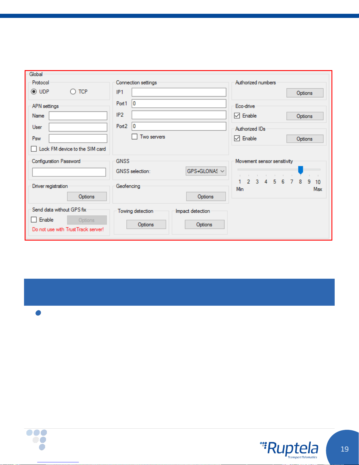
4.3.1 Global settings
The first part of the configuration tool is “Global” settings. Global include connection settings and other
settings independent from the profile settings – global settings are the same for all profiles.
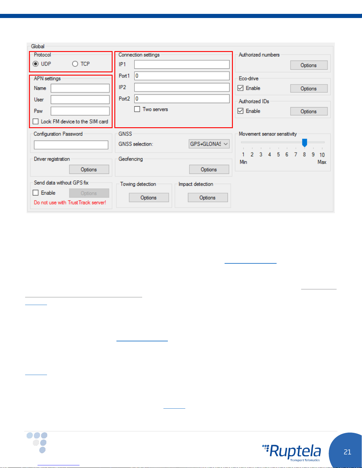
Connection settings here you should enter server IP and port that the device should connect to. The IP
can be entered in the numeric format: 255.255.255.255. You can also use a Domain name (not exceeding
40 characters). IP 2 is a backup IP address, which is used when the device is unable to connect to the first
server.
Note
Please have in mind that ports for TCP and UDP transfer protocols usually are different – please select the
correct transfer protocol and enter the correct port.
Two servers – checkbox changes the logic described above. It enables a two servers mode – the
same data is repeatedly transmitted to another server with IP2, unless we get a timeout. IP1 is
dedicated IP for server, from which we get the ACK’s for our record packets sent. After we get the
ACK from this IP, record data is considered as successfully transmitted to the server and it is
removed from the memory.
In this mode data is sent to IP2 only when connection to the IP1 is established. Packet, which is
sent to the IP1 server is also sent to the IP2 server.
Only records are going to be send to the IP2. Data packets such as Transparent Channel,
Tachograph, SD card, Garmin will not be send to the IP2.
Unable to send data:
When unable to establish connection to IP1, device does not connect to the IP2 as well. When
connected to IP1 and doing data transmission, but IP2 is unreachable – after receiving ACK from IP1
server, data is removed from memory, which can cause information loss in IP2 server.
Page 21
Note
Two server mode doubles the amount of data that is being sent. Before using this functionality consider
the cost which arises from the higher data traffic.
Protocol sections allows you to choose from two protocols. UDP protocol is less reliable than the TCP, but
also uses less traffic. TCP uses more internet traffic, but it is more reliable. Choose one according to your
needs.
APN settings are needed for internet connection. These settings must be provided by your mobile network
provider. Without APN settings the device will not send any data.
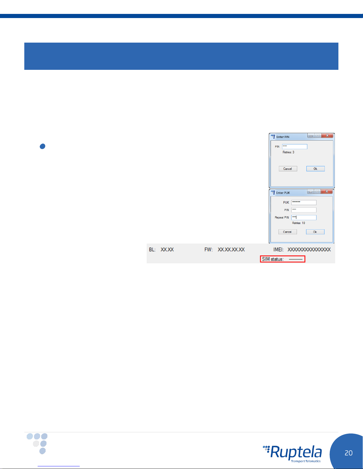
If you choose to enable Lock FM device to the SIM card check-box
you will be required to enter SIM card’s PIN code every time you try to
connect to the device via USB cable. As long as it is checked you will not
be able to use a different SIM cards with this device.
If the wrong PIN is typed in more than three times, either the SIM card
become locked.
It can be returned to its original unlocked state by entering a PUK,
provided by the service operator after verification. If the wrong PUK is
entered ten times in a row, the device will become permanently blocked
and unrecoverable, requiring a new SIM card. Once you enter the PUK
code, you must set a new PIN.
SIM status section at the
bottom of the configuration tool displays SIM card related information.
Total of seven different statuses are available:
I. Ready – PIN code is known or PIN code check is disabled. GSM/GPRS modem can operate
normally.
II. Error – Represents a wide range of possible problems. Common reason would be old FW
version, which does not support SIM commands.
III. Unknown – Communication between device and GSM/GPRS modem failed, SIM status is
unknown.
IV. PIN Request – SIM card requests a PIN code, FM device cannot provide it (code provided by
the device is incorrect).
V. PUK Request - SIM card requests a PUK code.
VI. Locked – This FM device is attached to a different SIM card.
VII. Not inserted – SIM card is not inserted.
Page 22
Configuration password allows to lock the configuration – without the password no one can change the
device configuration via cable. However, over-the-air update ignores the configuration password.
Driver registration is used to authorize vehicle start, identify driver and account working hours. Full
functionality description can be found at our documentation website, Driver registration.
Send data without GPS fix - device cold-start often causes problems, because it is not not sending data,
therefore user is unable to see parameter values until the GPS fix is obtained. In order to face these
problems new functionality, which enables sending data without GPS fix was implemented. This feature
cannot be used with TrustTrack server! Full functionality description can be found on our documentation
website.
GNSS allows to select positioning network – GPS, GLONASS or GPS+GLONASS. GPS+GLONASS by default
(
recommended not to change this
).
Geofencing allow to use internal geozones, configured directly into device. Full description can be found
on our documentation website, Internal geozones.
Towing detection - With Towing detection driver can be informed, that his car is being towed.
Information about such event is sent to the server, therefore driver might still have time to come back to
his vehicle before it is taken away. Full functionality description can be found on our documentation
website.
Impact detection – when this feature is active, FM device monitors its acceleration in all directions and
generates records, when acceleration exceeds configured limits. Clients can use this feature to get
notifications to the server about irresponsible drivers, who hit sidewalks or other obstacles. Full functionality
description can be found on our documentation website.
Page 23
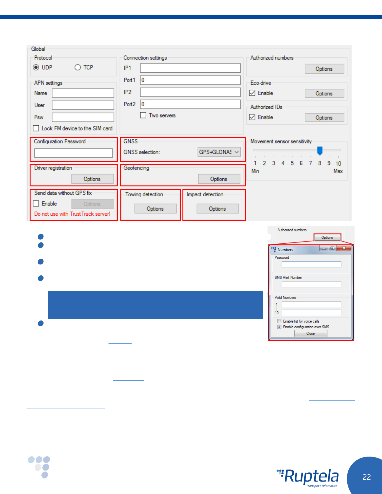
Authorized numbers
Set a Password to restrict access to the SMS commands feature.
SMS Alert Number. When specific I/O parameter is triggered, the
FM device will send an alert message to this number.
In the Valid Numbers table enter specific numbers that will be able
to send commands to the device.
If you check Enable list for voice calls entered numbers will be
able to make a call through the device.
Note
FM-Pro4 3G has no audio interface, therefore audio transmission is
not available.
Enable configuration over SMS checkbox controls configuration
over the SMS feature. Full functionality description can be found on
our documentation website.
ECO Driving options are used to choose sensitivity for the ECO Drive functionality. It helps to rate drivers
according to their safety or according to driver's behaviour. Full functionality description can be found on
our documentation website, ECO Drive.
Authorized ID’s allows you to fill in a list of authorized IDs who can start engine when ignition blocking is
used. More information about this functionality is available on our documentation website, FM-Eco4, Pro4,
Tco4 + Driver registration.
Movement sensor sensitivity allows you to configure movement sensor according to your needs. If you
slide the bar towards the Max, the sensor will detect even very slight movements. If you slide it to the Min,
than only stronger movements will be detected.
Page 24
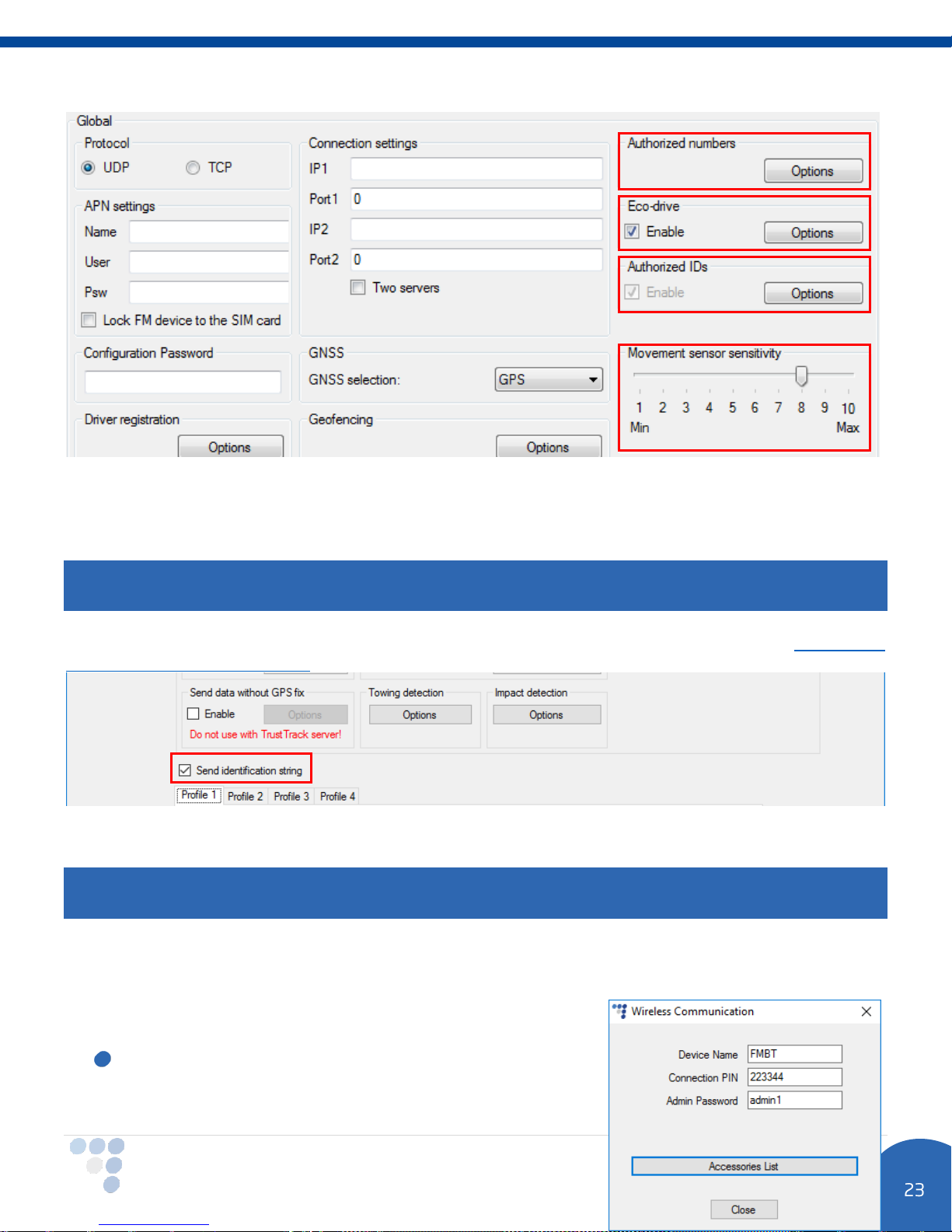
Send identification string feature forces FM device to send an identification packet to the server. After
that the device waits for the ACK packet from the server. Once device receives this packet, it begins data
transfer.
Note
If identification string feature is enabled, you cannot use transparent channel and vice versa.
For more information about this functionality go to our documentation website and look for “Transparent
channel and Identification string” document.
Wireless
Note
Wireless section is available only for FM-Pro4 BT device, which has built in Bluetooth module.
Wireless section contains Bluetooth communication settings. Add a tick to the Enable check box to make
your FM-Pro4 BT device discoverable by other Bluetooth devices. Click “Options” button to change basic
wireless communication settings.
The following fields are currently available in “Wireless
Communication” setting window:
Device Name – Give a name to your FM-Pro4 BT device.
Launch “OnTrack Connect” in your smartphone. Go to the
Page 25
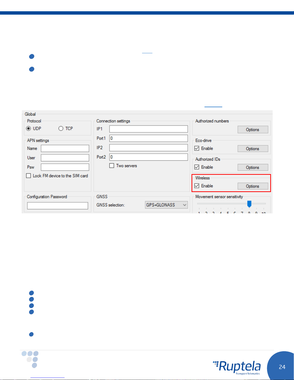
Bluetooth devices window. There, among other available Bluetooth devices you should be able to
see your device.
OnTrack Connect app user manual available here.
Connection PIN – You need to know this code in order to pair your smartphone with FM-Pro4 BT
device. In “OnTrack Connect” choose your unpaired FM device and enter this PIN code.
Admin Password – You need to know this password in order to connect to the already paired FM-
Pro4 BT device. In future it will be used to authorize extensive FM device configuration. For now you
can enter anything or just leave this field blank. In the “OnTrack Connect” choose a paired FM
device, enter its password and connect to the device.
Click the “Accessories list” button. It leads to the “Bluetooth Accessories” window. More information about
this feature and specific Bluetooth accessories available on our documentation website.
4.3.2 Profile settings
The second part of the configuration tool is for profile settings. This section also contain explanations for
other features that needs extensive configuration. Functionalities descriptions are available.
Each “Profile” is a settings set for specific circumstances (e.g. One profile for the vehicle, when it is
operated in the native country and another profile, when it is abroad).
Sleep can be
GPS/GSM modems. Deep sleep disables everything except DINs. When
possible to set a time limit. Once this time limit is reached, the device will switch to Sleep/Deep sleep mode.
If engine detection is set to
Disabled
or set to
Sleep
or
Always on
Deep sleep
. Sleep extends internal battery life by turning off
Sleep
– device will not go to sleep.
or
Deep sleep
is selected, it is
Device cannot go to sleep, if it is sending records.
Device cannot go to sleep, if Garmin is connected to it.
Any IO events that are set to generate records on
Data sending settings you can configure the data sending frequency and conditions.
The Enable check box must be enabled.
High
priority will wake up the device.
Page 26
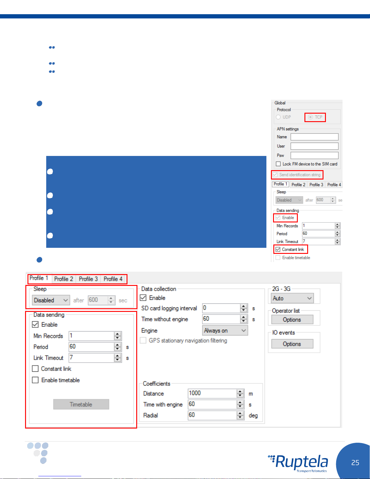
Min. records – Minimum number of records required to establish a connection to the server. If
the device detects less records than entered value, link to the server will not be opened.
Period – sets how often the device will check for required number of records.
Link timeout – this value indicates how long the device should wait before closing the link, after
this link was successfully established with the server and all the records had been sent. The
default value is 7 seconds, it is recommended not to change it.
Constant link check box forces FM device to check server link state and
keep it “alive” all the time. If server or network closes the link, the device
automatically reopens it and sends an identification packet – GPRS
command 15/115. Therefore, the device is always accessible via GPRS.
By default this check box is greyed out. In order to enable this feature
you must select TCP protocol, tick the Send identification string and
Data sending Enable check boxes.
Notes
If constant TCP link functionality is enabled, the device ignores link
timeout parameter for the main connection and uses it only for the
emergency connections.
If constant TCP link functionality is enabled, then timetable and sleep,
deep sleep modes are disabled and vice versa.
If constant TCP link functionality is enabled, then TCP protocol and
Send identification string checkboxes are enabled and greyed out in all
4 configuration profiles.
If constant TCP link functionality is enabled, then in this profile Data
sending “Enable” checkbox is enabled and greyed out.
Timetable allows you to select particular days and hours for the data to
be sent.
Page 27
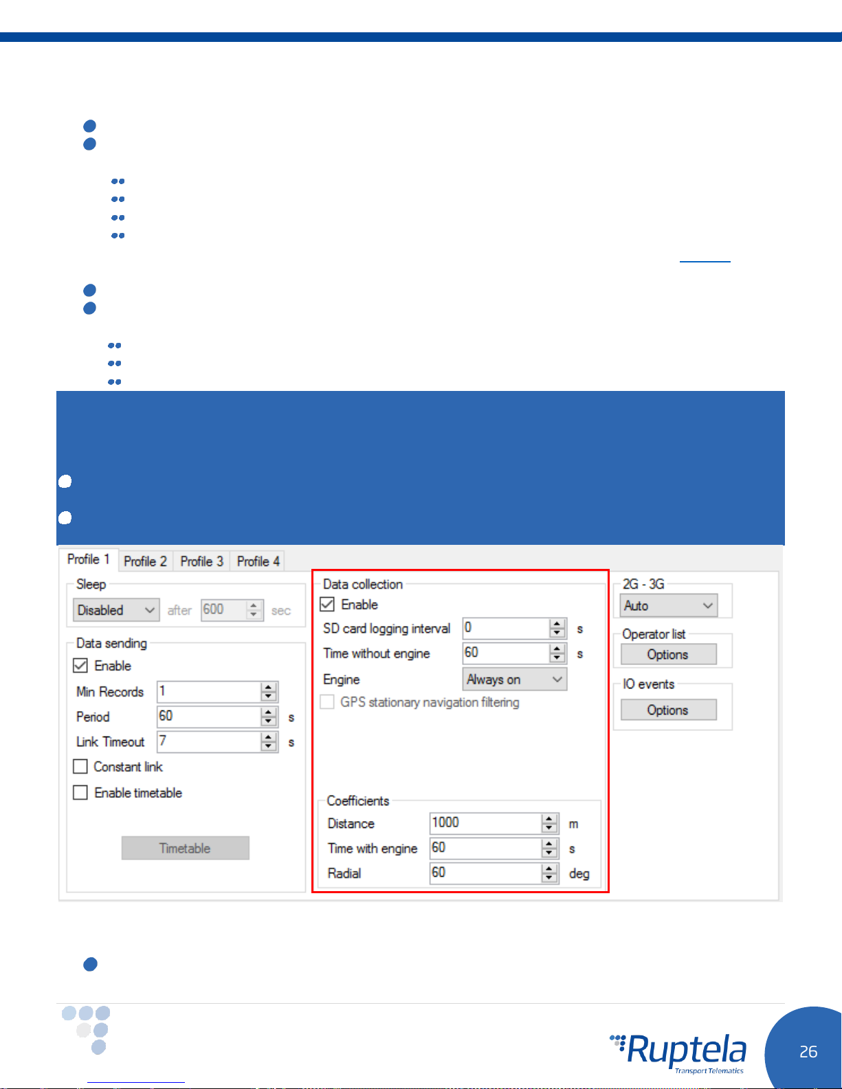
Data collection must be enabled to collect the information.
Time without engine means how often records should be made, when the engine is off.
The Engine drop box allows you to choose how the device will pick up the ignition (consider that
the engine is on).
Always on
Ignition (DIN4)
MovSensor
Custom
engine ignition. Full functionality description can be found on our documentation website.
GPS stationary navigation filtering eliminates GPS jumps, when the vehicle is not moving.
Coefficients are used to collect records in addition to the engine on/off parameters. They help to
get a more accurate route of the vehicle. A record will be made when:
Distance that was set - has been achieved.
Time with engine has passed.
Radial turn of degrees that was entered - has been detected.
– No ignition pick up, engine considered always to be on.
– Digital input 4 is default DIN used for ignition pick up.
– Detect movement of the vehicle and consider engine to be on.
– Custom Ignition functionality enables user to select more than one condition to detect
Note
Keep in mind that FM Device is not designed to have a perfectly accurate time tracking function. Due to
various reasons minimal deviations are possible. Over prolonged time periods these small deviations might
add up and produce time tracking inaccuracies. Few examples:
Device is configured to track one event for 1h. However actual event tracking might last for 1h ± Error
(i.e. 5 seconds).
Device is configured to gather records every second. Depending on the device’s state, record gathering
time might deviate and last longer (i.e. 2, 3 or even 5 seconds).
2G – 3G section allows to set device operation mode either to 2G or to 3G. This feature is supported in
FM4 devices that have UG96 GSM modem. Three different operation modes can be set:
Auto
– Default option. FM device uses 3G when it is available. If for some reason 3G is unavailable
or it becomes unavailable during operation, device makes 3 attempts to connect to the UMTS
Page 28
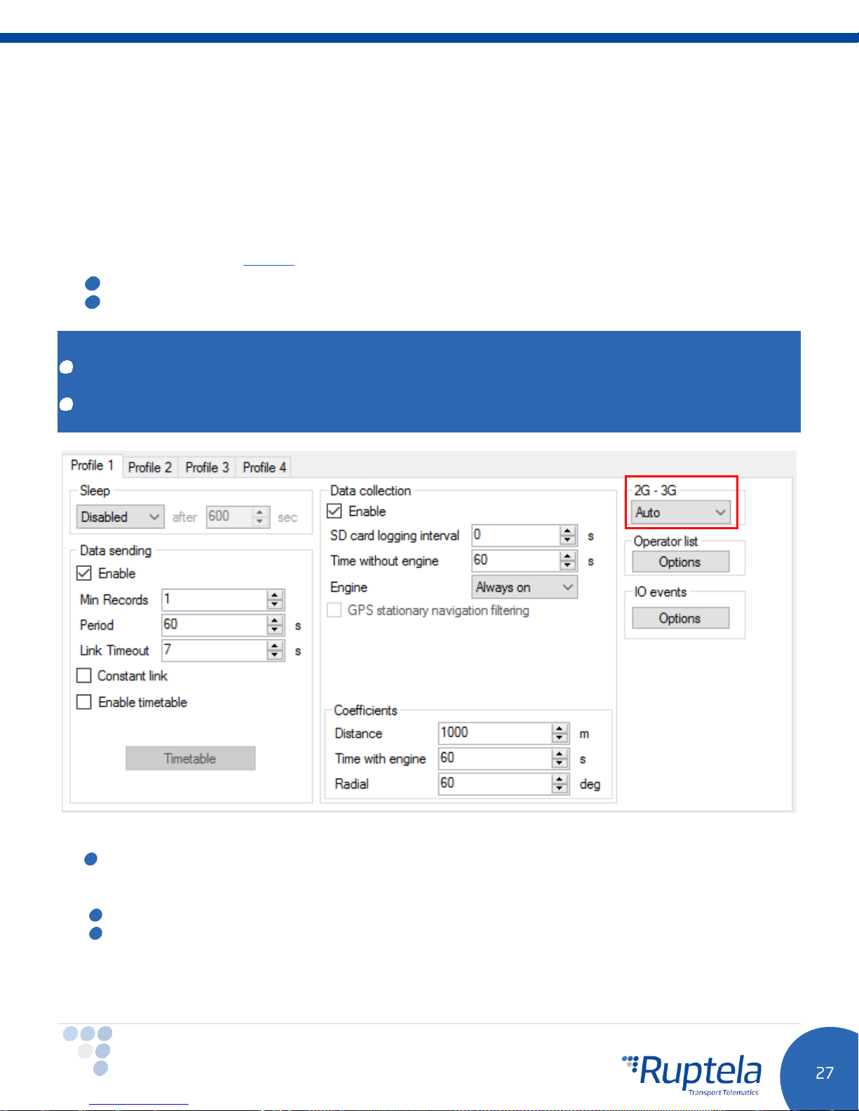
network. In case this is not possible, it will automatically switch to GSM/GPRSS (2G mode) and stay
in this mode.
Device can be forced to switch back to UMTS network with SMS command. Command structure
would be:
password set3g 1/0 –
where value: ‘1’ means enabled and ‘0’ means disabled.
Example: password set3g 1 –
More information about SMS commands available in “SMS Commands List” which can be found on
our documentation website
GSM only
UMTS only
– Device operates only in 2G mode.
– Device operates only in 3G mode.
In this example, 3G would be enabled.
Note
FM-Pro4 devices with hardware versions that do not have UG96 modem operate only in 2G mode. For
these devices
Almost all functionalities that are available in FM-Pro4 devices are also available in FM-Pro4 3G. Among
previously mentioned exceptions, this device also does not support modem firmware update over the air.
“Auto”, “GSM only”
and
“UMTS only”
options have no effect.
Operator list
st
1
… 3rd Profile tab – operators list in this tab allows selection of operators used in current profile.
If operator that is in the list was not found, then device will search for other operator in the list. If
no operators were found, device will switch to the next profile.
Blacklist has opposite meaning for operator list. Operators that are in blacklist will not joined.
Enable priority in list - search for operators according to number in list. If it is not selected,
device will search for operator randomly.
Page 29
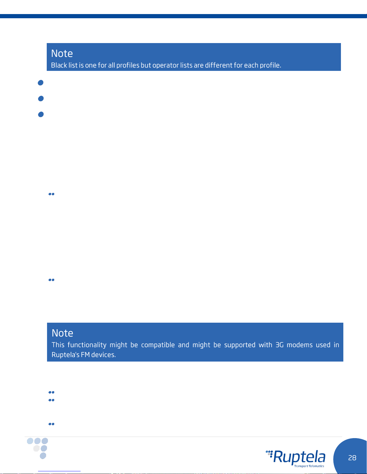
GPRS Attempt – how many times device will try to attach to operator`s GPRS before trying
another operator.
GPRS data counter – how many kilobytes of data device should send before performing next
operator search.
Temporary blacklist – temporal ban period in seconds. Sometimes when the FM device connects
to the operator with unavailable GPRS, the device is connected, but cannot transmit any data to the
server. In such case temporary blacklist is used. Operator with unavailable GPRS gets into the
temporary blacklist, which prevents the FM device’s connection to this operator on the next operator
search.
In other case, device connects to mobile operator and successfully obtains GSM and GPRS signal.
However, records still do not reach the server. Device has an ability to work around the faulty
network (i.e. when network connection is lost) by putting this operator into the temporary backlist.
Ban in this case is implemented via 2nd level temporary black list logic. Network verification is done
as follows:
Server pinging – device performs server pinging only when there is no response (no ACK) from
the server and if the connection to server is not available.
It will make up to 3 separate pinging attempts. If any of these attempts are successful, network
will be verified. In an ideal case, server responds after the first attempt, network is verified and
no more pinging operations are needed.
If the server fails to respond to all of them, the device will switch to another operator, after
putting current operator into the temporary black list.
During a single pinging operation device transmits approximately 256 bytes of data. If device
needs to make all three attempts, it will send approximately 768 bytes.
Operator is also added to the temporary black list, when the device receives "13110" error code
from the operator. According to Quectel M95 AT command manual the first number in error
code “1” stands for “Cause for protocol stack (PS) layer” and the rest “3110” stands for
"Network fail".
Received trouble codes can be monitored with the help of "GSM trouble codes" IO parameter.
Key point about the temporary black list:
Ban period is configurable. When all operators get into the ban list, ban list is cleared.
Banned means that the terminal was not able to get the GPRS context, it was unable to connect
to the operator, server failed to respond to 3 consecutive ping requests or that the terminal
received "3110" error code from the mobile operator.
Ban list is in the RAM the memory, it is cleared after reset or power off.
Page 30
4.3.3 IO settings
IO events “Options” buttons opens up a new “IO settings” window, here you can enable or disable IO
parameters that will be sent to a server.
1. You have 80 slots for parameters. Select a slot that you want to enable.
2. In the IO properties section tick the Enable check box, otherwise the slot will remain empty.
3. ID contains the parameter list. Choose a parameter you want to enable for the selected slot. One
parameter can be enabled only one time.
4. Level is used with hysteresis mode,
5. Delta is used with hysteresis mode,
6. Average. Some parameter`s values change rapidly and do not correspond any valuable information.
Averaging values for some period of time gives a more usable value of the parameter (e.g. fuel level
often oscillates. Averaging gives you an approximated value that correspond to the real fuel level in the
tank).
7. Event on – describes how the parameter will be measured and sent:
a. “Monitoring” – The parameter value is always monitored and sent with every record.
b. “Change” – when the value changes, a record will be made regarding this change. However, the
parameter is monitored and sent to the server with every record.
c. “Hysteresis” – The record is generated because of the specified change in the parameter value. E.g.
parameter is a “Power supply voltage”. Level sets a point of reference, in this case 12700 mV. Delta
is a variation in the value, e.g. 1000 mV. The record will be generated (because of the parameter
value change), when a Power supply voltage drops to < 11700 mV and/or > 13700 mV. You can
select the condition “on rising” or “on falling”.
8. Select Include data only on event to get a parameter value only when the condition (set in step 7)
is met. In other cases the parameter value will not be included in the records.
9. If Priority is set to “High”, the record will be sent immediately, disregarding data sending settings. If it
is “Low”, the device will wait for suitable conditions to open a link to server.
10. Upon an event of a value change in some parameter you can configure the device to Switch to the
other profile.
see 7.c below for more details.
see 7.c below for more details.
Page 31
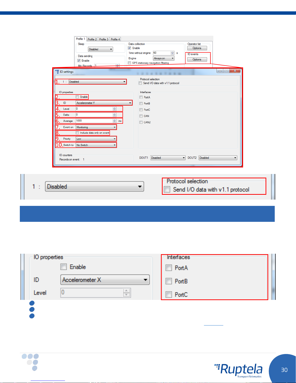
Protocol selection section has a checkbox, where you can choose to “Send I/O data with v1.1 protocol”.
Note
Enabling this checkbox will result in the loss of all unsent records.
Interfaces section gives ability to enable or disable all of the device’s interfaces (described in 3.6
paragraph).
Port A – RS232 PortA.
Port B – RS232 PortB.
Port C – RS485 PortC.
More information and connection instructions available on our documentation website.
Bellow you will find checkboxes for the K-Line, CAN and CAN2 interfaces.
Page 32
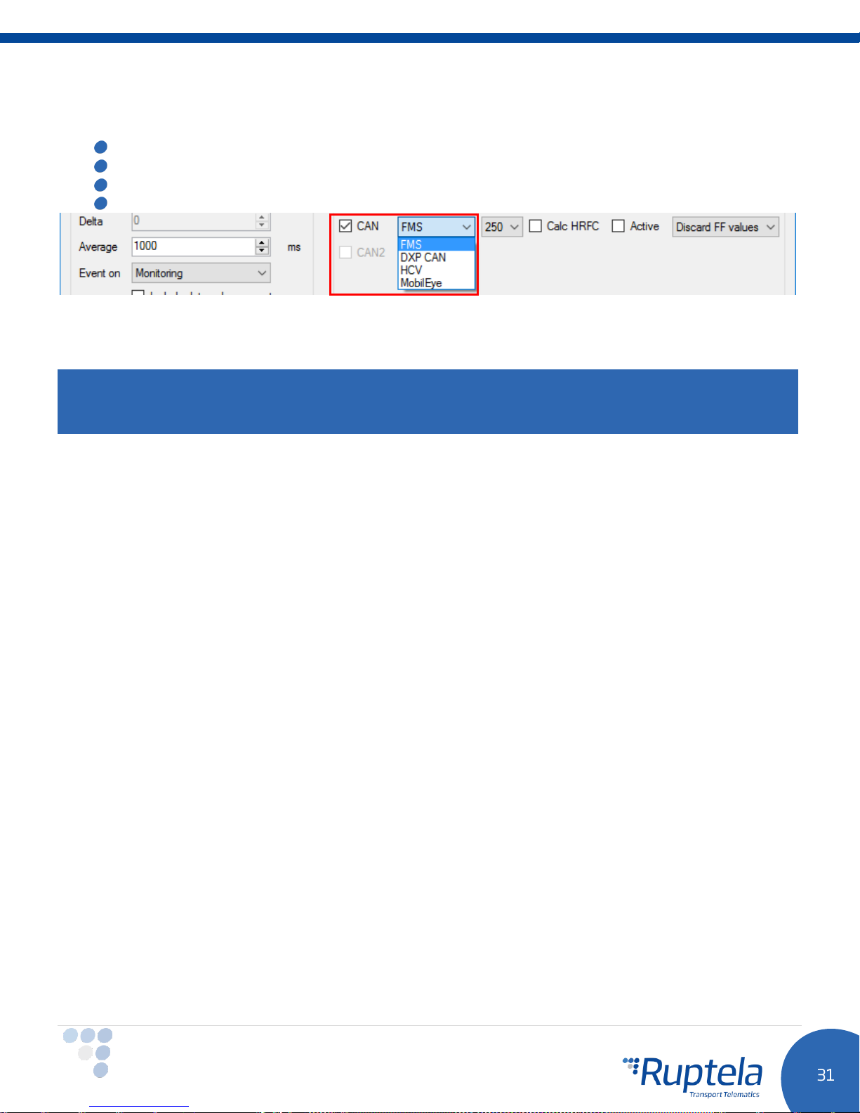
CAN – if you put a tick in the 1st CAN interface checkbox, then a dropdown list appears, where you can
choose one of the following:
FMS -
for vehicle CANbus (FMS) information reading.
HCV -
for HCV CAN (heavy commercial vehicles) information reading.
DXP CAN –
MobilEye
CAN2 – 2nd CAN interface checkbox has all the same options as CAN interface described above.
DXP electric vehicle information reading.
– for communication with MobilEye device.
Note
Only one CAN line work at the same time. Connect your hardware to one of the interfaces and configure it
accordingly.
Additional fields can be used in conjunction with CAN interfaces. This depends on interface configuration.
Smart CAN IO selection
“Smart CAN IO Select” functionality allows to add CAN IO parameters only when
mode is enabled on the CAN interface. When other modes are set, CAN IO parameters are hidden. By
default Smart CAN IO Selection is always on.
First we will describe these CAN modes. After that, there will be a section explaining how to turn Smart
CAN IO Selection off and why it could be useful.
Something to consider, when Smart CAN IO Selection turned on:
FMS, HCV or DXP CAN
Enabling/disabling CAN interface might cause some issues. Let’s say Smart CAN IO Selection is on. One of
the CAN interfaces is enabled and
parameters (
disable this CAN interface, some of the CAN IO parameters will be disabled as well. You will be warned
about this with a new pop up window.
Similarly, if you change CAN
be disabled.
CAN HCV:
Autobaud – If this checkbox is enabled, device will automatically determine a correct baud rate that
should be used, while receiving data from vehicle’s onboard computer.
Active – If this checkbox is enabled, device will do both, receive and send data to the vehicle’s onboard
computer.
CAN engine speed, CAN wheel based speed etc.
FMS, HCV
FMS
or
HCV
or
DXP CAN
mode is selected in the drop down menu. Some CAN
) are added to the IO list. If you decide to
mode to something else, the CAN IO parameters will
Page 33
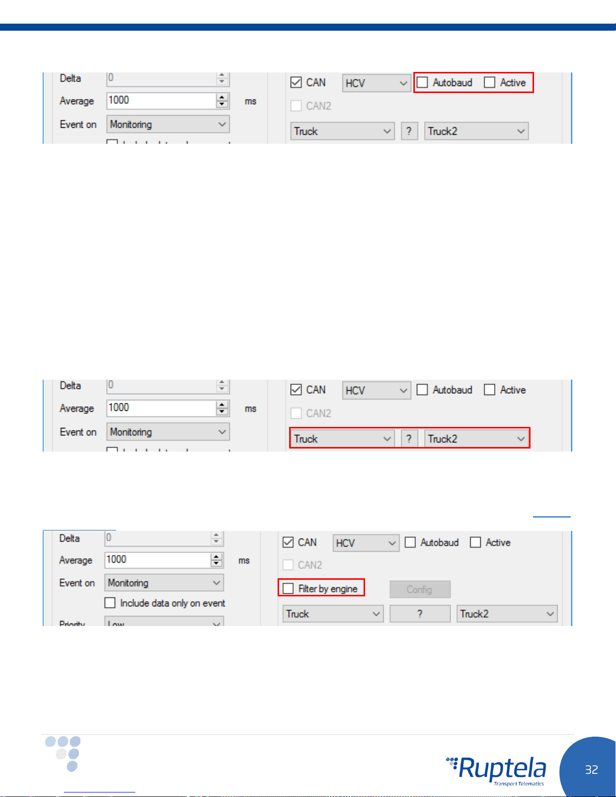
HCV Group selection dropdown list.
HCV Sub group selection dropdown list.
? – HCV selection by vehicle brand, model and year.
Something to consider, when Smart CAN IO Selection turned on:
With HCV mode set on the CAN interface, only specific CAN IO parameters that are supported for currently
selected HCV Group and Subgroup will be visible. Unsupported parameters will not displayed in the list.
This feature helps to avoid confusion, since different HCV Groups, Subgroups support different number of
CAN IO parameters.
Changing configuration from one HCV Group, Subgroup combination to another might cause some issues.
Consider this case. During configuration you set some HCV Group, Subgroup. After this the IO list contains
only supported CAN parameters that are available for this specific HCV Group and Subgroup combination.
Let’s say you enable some of these IO parameters. Now, if you decide to change current HCV Group,
Subgroup combination, some of those IO parameters might be automatically disabled. It means that once
again you would have to enable them one by one, which is a very time consuming task.
Filter by engine
This feature allows to filter CANbus data by engine state. It helps to solve errors in EcoDrive data
calculations, which arise from invalid CANbus data. Errors occur, while vehicle’s ignition is being turned off
and during a short time period, after it was turned on. Full feature description is provided in the “CANbus
filter by engine” document.
CAN FMS:
Baud rate - two possible options are available in the FMS Baud rate dropdown list:
250, 500
. Data
transfers rate depends on vehicle.
Page 34
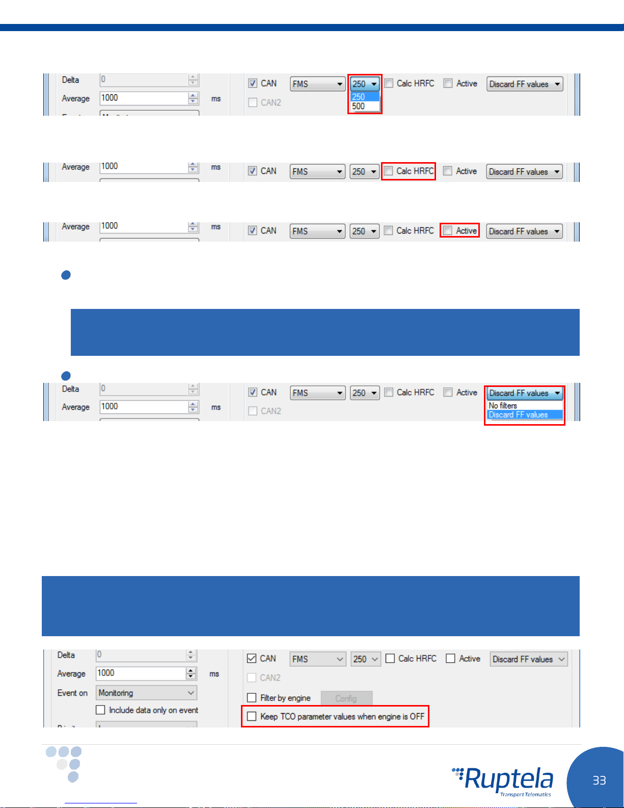
Calc HRLFC - enables fuel consumption recalculation from fuel rate for FMS CANbus mode. Recalculation
works only when high resolution fuel consumption data from CANbus is not available.
Active – If this checkbox is enabled, device will do both, receive and send data to the vehicle’s onboard
computer.
FMS data filters drop down menu. It is used to set FMS data filter:
Discard FF values -
to server. It discards FMS data packets with FF values. In this case, new records contain previously
obtained FMS parameter values (from valid data packets).
default option. Device sends only valid data (according to SAE J1939 standard)
Note
Filter is applied only to the following FMS parameters:
fuel used, Engine speed, Wheel based speed, Trailer weight, Cargo weight.
No filters
– Device sends all data to the server.
Engine total fuel used, High resolution total
Filter by engine functions the same way as described in the CAN HCV section.
Keep TCO parameter values when engine is OFF
Problems might arise with driver working time calculations, when FMS gateway and digital tahograph
switches to sleep mode and are not providing driver ID, working state and other driver related information.
When enabled, this functionality allows FM device to keep last known driver related I/O parameter values,
when the engine is OFF and there is no communication with the digital tachograph.
Feature affects the following I/O parameter values:
TCO first driver ID 1, TCO first driver ID 2, TCO second driver ID 1, TCO second driver ID 2, TCO first driver state, TCO second
driver state, TCO first driver card, TCO second driver card.
Note
In certain cases this feature might cause errors in “Time analysis” calculations. I.e. when driver changes his
status or removes the card from tachograph, while engine is OFF and there is no communication with
digital tachograph. In that case device would provide wrong data in mentioned IO elements.
Page 35
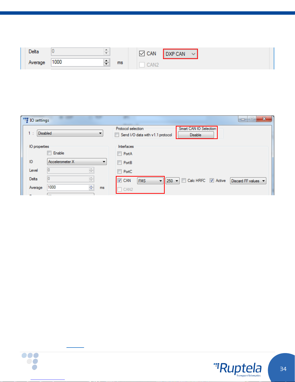
DXP CAN:
This mode can be used to read CANbus information from electric DXP vehicles.
Disable Smart CAN IO Selection
The section itself and the “Disable” button will be visible only when one of the CAN interfaces is enabled
and the
selected. With other modes, both are hidden.
FMS, HCV or DXP CAN
mode is selected. Also when Port C is enabled and the
J1708
mode is
Click the “Disable” button to turn the Smart CAN IO Selection off. Button will be dimmed. To turn this
feature back on, close the “IO Settings” window and restart the configurator. Smart CAN IO Selection
functionality will go back to its default ON state.
Use Smart CAN IO Selection “Disable” button, when you need to switch from one CAN interface to another,
without losing enabled CAN IO parameters. Don’t forget to set the same configuration
(Example: You have configured CAN FMS 250 Active on the 1st CAN interface. You have enabled few CAN
IO parameters. Now you want to switch to the 2nd CAN interface without losing those parameters. Click
“Disable” button in Smart CAN IO Selection section. Disable 1st CAN interface or set different mode. Enable
2nd CAN and set FMS 250 Active. Switch is complete.
Similarly, you could transfer CAN IO parameters for HCV mode. Same Group, Subgroup combinations has
to be used on both interfaces. For example, switching from 1st CAN HCV TRUCK-TRUCK1 to 2nd CAN HCV
TRUCK-TRUCK1 is allowed.
Switching form FMS to HCV or from HCV GroupX, SubgroupX to HCV GroupY, SubgroupY is not
recommended. Some CAN IO parameters eventually would be lost.)
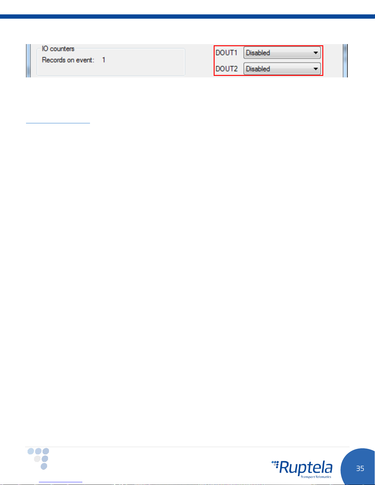
Digital outputs section
DOUT1 and DOUT2 – dropdown lists let you choose DOUT operation mode. More information available on
our documentation website
Page 36
4.4 Integration protocol
All integration related questions and documentation can be acquired from Ruptela technical support:
Page 37
5 Installation recommendations
5.1 Device installation
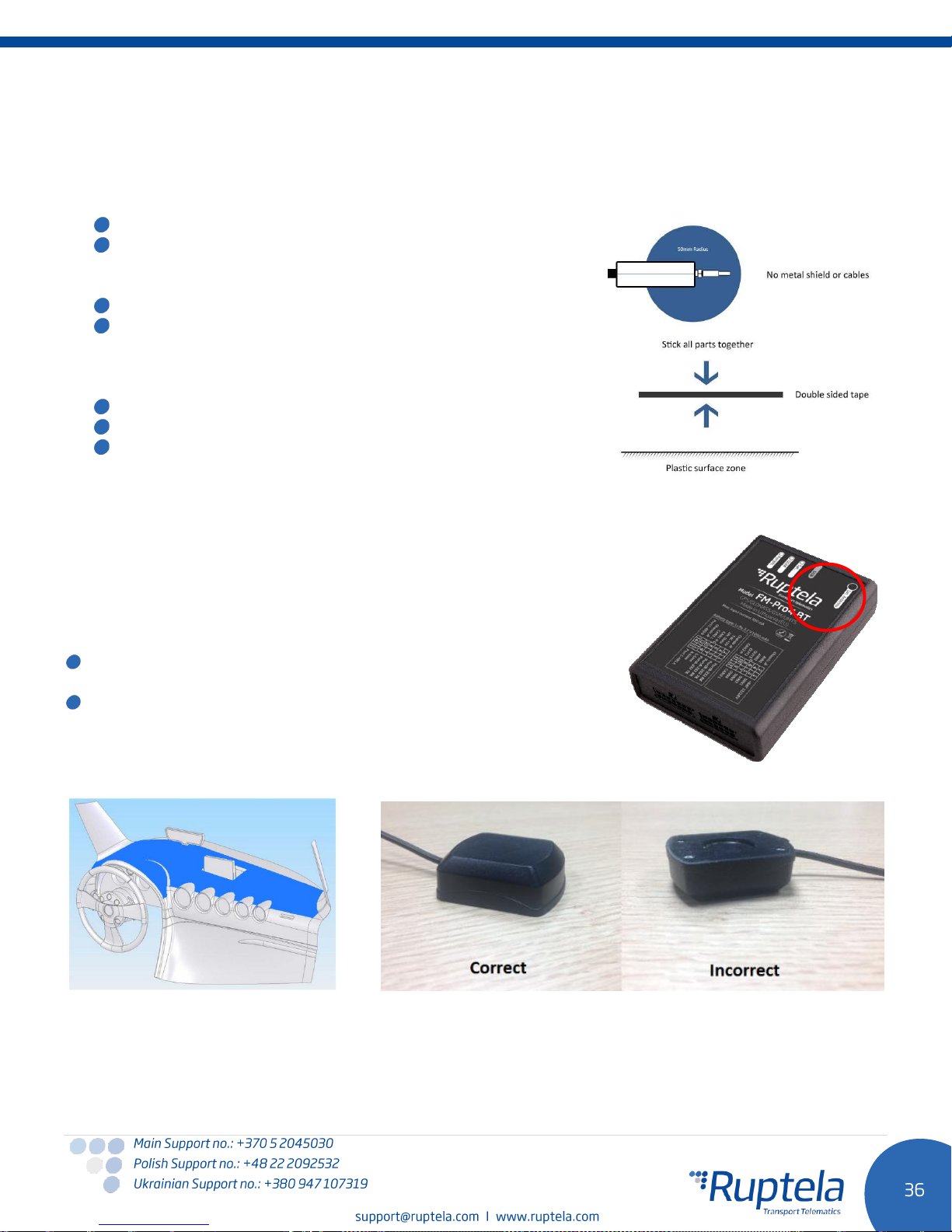
When installing device into a vehicle please obey these instructions, otherwise your device may not work
properly.
Device should not be seen or easily reached.
Device should be firmly fixed to a flat surface. Please avoid
mounting it near the metal surfaces or cables (see the
picture below).
Device cannot be fixed to heat emitting or moving parts.
Device has built in accelerometer, therefore it is sensitive to
movement. It is recommended to choose a stable installation
position, where it is not subjected to vibrations and/or
oscillations.
Device can be fitted with double sided stick tape or zip-ties.
Wrong device mounting may cause malfunction.
SIM card should be inserted in the device while the
connector is plugged off (while device has no power).
5.2 FM-Pro4 BT device
Your FM-Pro4 BT device contains Bluetooth module. Choose
installation location carefully. Approximate Bluetooth module
position within the device is marked in the picture on the right. To
ensure the best possible connectivity between Bluetooth devices
follow these steps:
FM-Pro4 BT device with Bluetooth module should be installed
facing up.
Please avoid mounting it near metal surfaces or cables.
5.3 Antenna installation
It is recommended to place GPS/GLONASS antenna behind the dashboard as close to the window as possible.
 Loading...