

Page 1
Page 2

Table of contents
1 Preface ................................................................................................................................... 2
1.1 Use of this document ........................................................................................................ 2
1.2 Document change log ....................................................................................................... 2
2 Introduction ............................................................................................................................ 3
2.1 Purpose ........................................................................................................................... 3
2.2 Acronyms ......................................................................................................................... 3
2.3 Legal Information ............................................................................................................. 3
2.4 Safety .............................................................................................................................. 3
2.5 Battery handling safety ..................................................................................................... 4
2.6 References ....................................................................................................................... 4
3 Device description ................................................................................................................... 6
3.1 About .............................................................................................................................. 6
3.2 Package contents ............................................................................................................. 6
3.3 Physical characteristics ...................................................................................................... 6
3.4 Technical characteristics .................................................................................................... 7
3.5 Inputs/Outputs and OBD2 pin out ...................................................................................... 8
3.6 Peripheral accessories ....................................................................................................... 8
3.7 Certification ...................................................................................................................... 8
3.8 LED Status ....................................................................................................................... 8
3.8.1 LED when GNSS fix is acquired .................................................................................... 8
3.8.2 LED when GNSS fix is not acquired .............................................................................. 9
4 Device preparation ................................................................................................................ 10
4.1 Opening/Closing the device ............................................................................................. 10
4.2 Inserting a SIM card ....................................................................................................... 11
4.3 Connecting the USB cable................................................................................................ 11
5 Device configuration .............................................................................................................. 12
5.1 Driver installation............................................................................................................ 12
5.2 Sample configuration ...................................................................................................... 14
5.3 Advanced configuration ................................................................................................... 16
5.3.1 Global settings ......................................................................................................... 17
5.3.2 Profile settings ......................................................................................................... 19
5.3.3 IO settings .............................................................................................................. 24
5.4 Integration protocol ........................................................................................................ 27
6 Device installation ................................................................................................................. 28
Page 3
1 Preface
1.1 Use of this document
This document provides required information for proper device handling, preparation, configuration
and installation to a vehicle. This document has a linear structure – from the device package box
reception to the recommendations on how to install the device to the vehicle. However it is not
overfilled with unnecessary information. You will find only basic descriptions about various functions
and actions needed to start using the device with the reference to extensive descriptions of the
contents.
The following markings are used to highlight important information:
Notes contain important information that you need to pay attention to.
Note
Notes like this contain important information!
Actions and various elements of the software required for configuration of the device are
marked in bold.
All actions are described in sequence in the following five sections: Introduction, Device
description, Device preparation, Device configuration and Installation recommendations.
1.2 Document change log
Date
Version
Change details
2015-08-01
1.0
Initial draft.
2016-01-19
1.1
Battery safety.
2016-01-26
1.2
Towing detection, Sleep timer, Voltage thresholds for Virtual ignition.
2016-02-12
1.3
SELV Limited power source, device installation position.
2016-04-18
1.4
2nd level temporary black list, geozones removed.
2016-04-20
1.5
Firmware downgrading and older firmware support restrictions.
2017-02-07
1.6
“Constant TCP link” functionality description in “Profile settings” chapter.
2017-03-09
1.7
Changed DIFF file description in “Advanced Configuration” chapter.
2017-04-07
1.8
Added option to disable OBD Pin1 automatic check.
2017-05-22
1.9
“GSM tracking” feature description in “Global settings” chapter.
Configurable sleep mode description in “Profile settings” chapter.
2017-06-08
1.10
Automatic IO enable function in IO setting chapter.
2017-08-30
1.11
Debounce description added in "IO settings" section.
2017-12-22
1.12
Added note regarding greyed out fields in “Global settings”.
Page 4

2 Introduction
2.1 Purpose
The purpose of this document is to provide physical and technical data of the device, to explain
device’s behavior and how various conditions are indicated. Also, device preparation for operation and
its configuration instructions are included.
2.2 Acronyms
AC / DC – Alternating Current/Direct Current;
ACK - A signal to acknowledge the receipt of data;
GLONASS – Global Navigation Satellite System;
GNSS – Global Navigation Satellite System;
GPRS – General Packet Radio Service;
GPS – Global Positioning System;
GSM – Global System for Mobile Communications;
I / O – Inputs / Outputs;
LED – Light Emitting Diode;
PC – Personal Computer;
PCB – Printed Circuit Board;
SELV – stands for Safety Extra Low Voltage. A SELV circuit is a secondary circuit which is so designed
and protected that under normal and single fault conditions, its voltages do not exceed a safe value.
SMS – Short Message Service;
UMTS – Universal Mobile Telecommunications System;
2.3 Legal Information
Copyright © 2017 Ruptela. All rights reserved. Reproduction, transfer, distribution or storage of parts
or all of the contents in this document in any form without the prior written permission of Ruptela is
prohibited. Other products and company names mentioned in this document are trademarks or trade
names of their respective owners.
2.4 Safety
All the associated (additional) equipment such as PC’s, batteries, sensors etc., shall meet the
requirements of standard EN60950-1.
Do not disassemble the terminal. If the enclosure of the terminal is damaged, or the
insulation of wires is damaged, first of all disconnect power supply cables from the power
supply source.
All of the wireless data transferring equipment produces interference that may affect other
devices, which are placed nearby.
The terminal can be installed or dismounted only by qualified personnel!
The terminal must be firmly fastened in the predefined location. Predefined location is
described in the mounting instructions.
The programming must be performed using a 2nd safety class PCs (with an autonomic power
supply).
Make sure that the terminal is installed in a place, where it will not be subjected to harsh
environmental conditions for extended time periods.
Page 5

Any installation and/or handling during a lightning storm is prohibited.
For configuration use cables that were purchased from Ruptela. Ruptela is not responsible for
any harm caused, while using wrong cables for the PC ↔ Terminal connection.
This crossed-out wheelie bin symbol means that waste equipment should not be disposed of
with your other household waste. The product must be taken to separate collection points at
the product`s end-of life.
This chapter contains procedures to help you safely operate the FM-Plug4/4+ terminal. By following
these requirements and recommendations, you will avoid dangerous situations. You must read these
instructions carefully and follow them strictly before operating the device! The terminal is supplied
from a car battery with these ratings: 12/24 V DC. The allowed voltage range from the battery is from
10 volts to 36 volts DC (
Supplied from SELV power supply source
).
To avoid mechanical damage, it is advised to transport the FM terminal in an impact-proof package.
The terminal is intended to be installed in a restricted access location, which is not accessible for the
operator.
2.5 Battery handling safety
When your device has a battery pack you must also observe the following cautions:
If the battery pack is mishandled, the battery pack can burst, cause a fire or even chemical
burns.
Do not crush and do not expose the battery pack to any shock or force such as hammering,
dropping or stepping on it.
Do not short circuit and do not allow metal objects to come into contact with the battery
terminals.
Do not expose to high temperature (limiting values provided in user manuals and datasheets)
such as in direct sunlight.
Do not incinerate or dispose of in fire.
Do not handle damaged or leaking lithium ion batteries.
Caution! If an incorrect type of battery is used for replacement, there is a high explosion risk.
Dispose used batteries according to the environmental requirements.
Any installation and/or handling during a lightning storm is prohibited.
When it comes time to replace your batteries, make sure you are disposing of the old batteries
properly so no laws are broken. Check with your local solid waste management district for any
outlets for household battery recycling. Everything from AAA cells to mobile phone batteries
and button cells must be separated from household rubbish. For disposal of small quantities of
batteries, see if your local hardware/auto parts store or battery retailer will accept them for
recycling. Recycling bins in shops or other recycling points can also be used. Note, that most
large battery recycling agencies and disposal companies are usually set up to serve industrial
or municipal customers with bulk amounts of batteries rather than individuals.
2.6 References
This document is designed to work in a conjunction with other documents. Documentation is kept
light, unnecessary information is omitted. Additional and extensive explanations can be found in the
documentation referenced below:
Page 6

FM-Plug4/4+ Datasheet – Contains technical data of the FM-Plug4/4+ device. Can be acquired
from [email protected]
Quick start guide – A quick guide for a better understanding of the device configuration process
and functions.
Peripheral accessories – Instructions on how to use peripheral accessories together with the FM-
Plug4/4+ device.
Website – Our documentation website that contains the latest firmware, configurator and
sample configuration files.
Microsoft Framework – This additional software is required in order to run our configurator.
VCOM drivers – Drivers are required in order to connect the device to a PC.
All links are also provided in corresponding sections, where additional information might be needed.
Note
Ruptela documentation website address: doc.ruptela.lt
Page 7
3 Device description
3.1 About
Ruptela‘s FM-Plug4/4+ device is a 1st generation low cost, low power consumption, compact FM
tracking device with easy pluggable OBD connector. It acquires its position by a GPS/GLONASS signal
and transfers data to a server via a GPRS cellular network. The FM-Plug4/4+ device features:
Low power consumption
Small size
Internal power supply*
Real time process monitoring
OBD2 fault code reading*
*Available only for FM-Plug4+ device.
3.2 Package contents
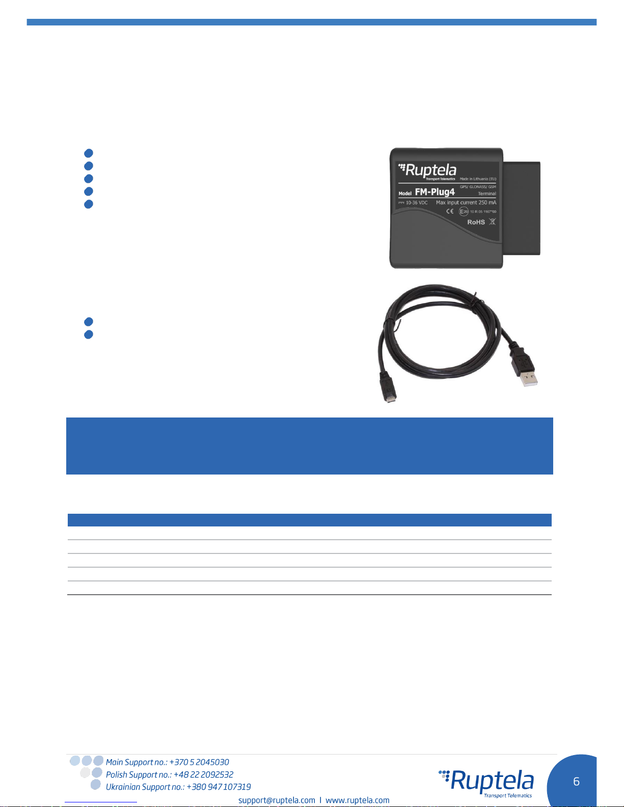
FM-Plug4/4+ device is supplied in a cardboard.
Package contents:
FM-Plug4/4+ device
USB 2.0 cable: USB A - male to micro USB B (as
optional accessory)
Note
Providing a SIM card is optional, according to your payment plan. The SIM card is necessary for
connection to the GSM network. The SIM card can be obtained from your local GSM service provider.
The SIM card can work with the terminal only when all SIM card security codes are disabled.
3.3 Physical characteristics
Properties
Enclosure dimensions
62,3L x 62W x 28H mm
Indication
1 LED
Housing
Plastic
Configuration interface
Micro USB
Connectors
OBD2
Page 8
3.4 Technical characteristics
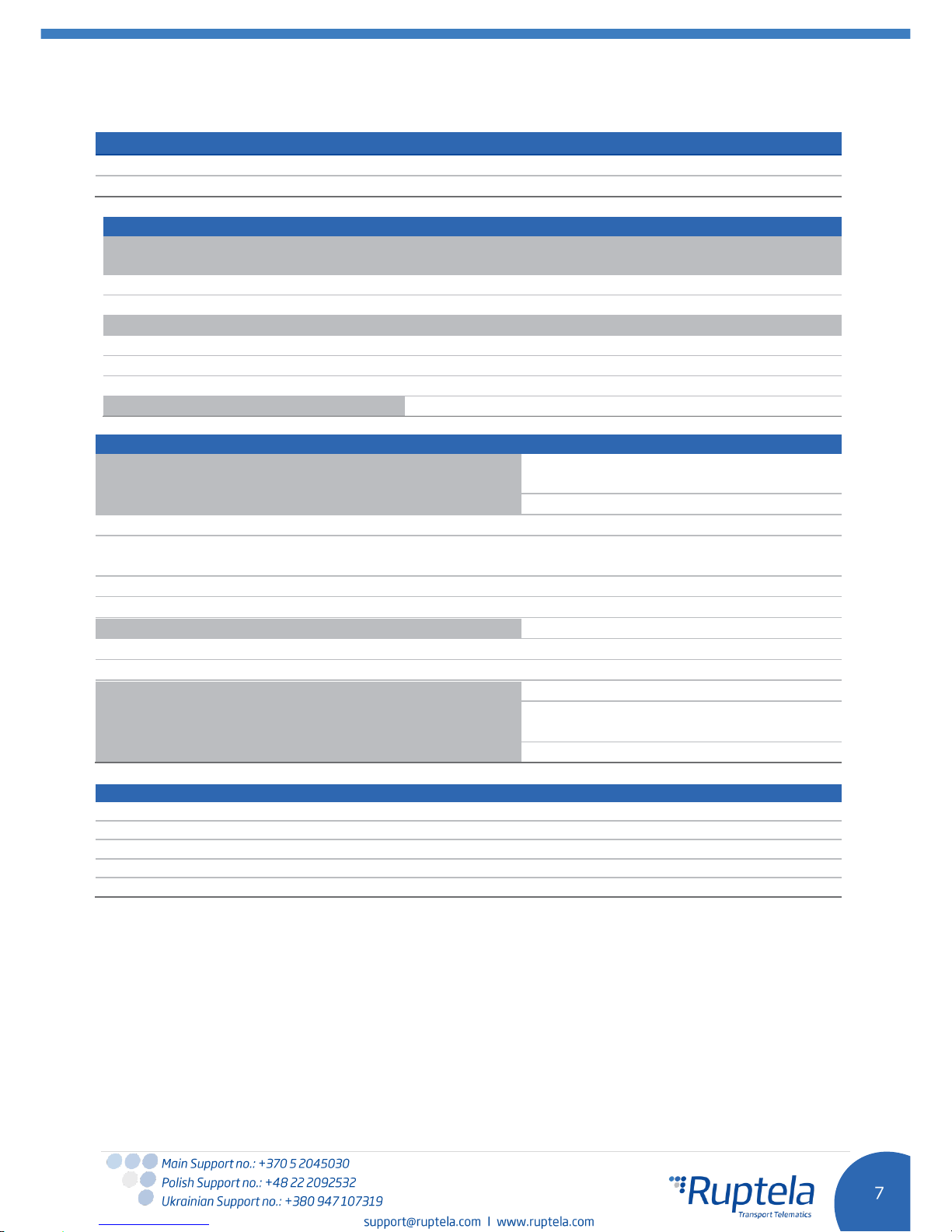
Power consumption @ 12V
FM-Plug4
FM-Plug4+
Idle mode, mA
250
350
Internal power supply
LiPo 3,7 V 190 mAh
1
Ambient temperature ratings, °C:
Temperature range for device (without
battery)
FM-Plug4
FM-Plug4+
Storage temperature, ⁰C
-40 ~ +65
-40 ~ +65
Operating temperature, ⁰C
-35 ~ +60
-35 ~ +60
2
Temperature range for battery
3
Charging, ⁰C
0 ~ +45
3
Discharging (operating), ⁰C
-20 ~ +60
3
Storage, ⁰C
-20 ~ +70
3
Humidity %
20 – 80
Common specifications
Power supply
10/24 V DC (range: 10 - 36 DC Supplied
from SELV Limited power supply source.)
GPS/GLONASS module
Internal, Ublox EVA-M8M
Channels
72 channels
-163 dBm (GPS)
-164 dBm (Glonass&GPS)
Cold start
30s
Aided start
3s
GPS/GLONASS antenna
Internal
GPS Frequency
1575,42± 3 MHz
GLONASS Frequency
1592-1608 MHz
GSM modem
Quectel M95
GSM antenna
Internal GSM850/GSM900
DCS1800/PCS1900 MHz @ GSM
Accelerometer
3-axis; 2g/4g/8g/16g
Protections
Short circuit protection
Reverse polarity protection
Electrostatic discharge protection on USB
Electrostatic discharge protection on sim card slot
4
Charging protection (on FM-Plug4+)
1
Currently parameter values only theoretical.
2
FM-Plug4+ only.
3
Currently parameter values are only theoretical.
4
If temp is >45C, charging is disabled, if >60C battery is disconnected from the system at all
Page 9
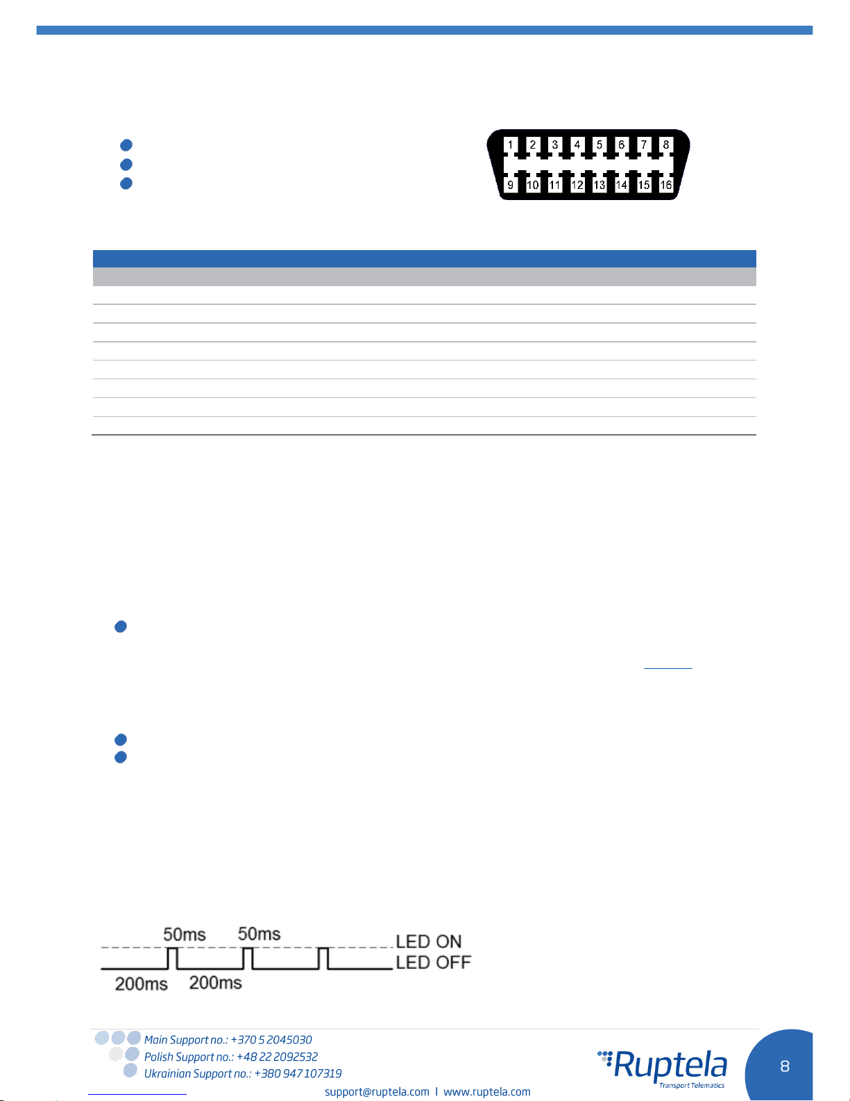
3.5 Inputs/Outputs and OBD2 pin out
Inputs/Outputs of the FM-Plug4/4+ device:
OBD2 Plug
LED
Microphone (internal)
An example of vehicle’s OBD2 socket pin numbering pattern is shown on the right. Pin designations
provided in the table below.
OBD2 Pin out – Vehicle’s side
PIN
Description
PIN
Description
1
5
Vendor Option
9 5Vendor Option
2
J1850 Bus High
10
J1850 Bus Low
3
5
Vendor Option
11 5Vendor Option
4
Chassis Ground
12 5Vendor Option
5
Signal Ground
13 5Vendor Option
6
CAN (J-2234) High
14
CAN (J-2234) Low
7
ISO 9141-2 K-Line
15
ISO 9141-2 L-Line
8
5
Vendor Option
16
Battery Power
5
Pin function depends on vehicle manufacturer.
3.6 Peripheral accessories
There are several peripheral accessories that can be mounted with the FM-Plug4/4+ device. With these
peripherals you can get even more features and extended functionality. All available peripherals can be
purchased from Ruptela. Please contact your manager for details.
Available on USB:
1 × Panic button (
This feature is under development.)
You can find peripheral accessories installation instructions and documentation on our website.
3.7 Certification
FM-Plug4/4+ devices have passed quality tests and comply with the following certifications:
E-Mark
RoHS
3.8 LED Status
The FM-Plug4/4+ device has a single LED to indicate various device’s states during device installation
and troubleshooting, it also indicates GSM/GPRS, GPS/GLONASS (GNSS) status
3.8.1 LED when GNSS fix is acquired
When GSM signal is not received, the LED is blinking as follows:
Page 10
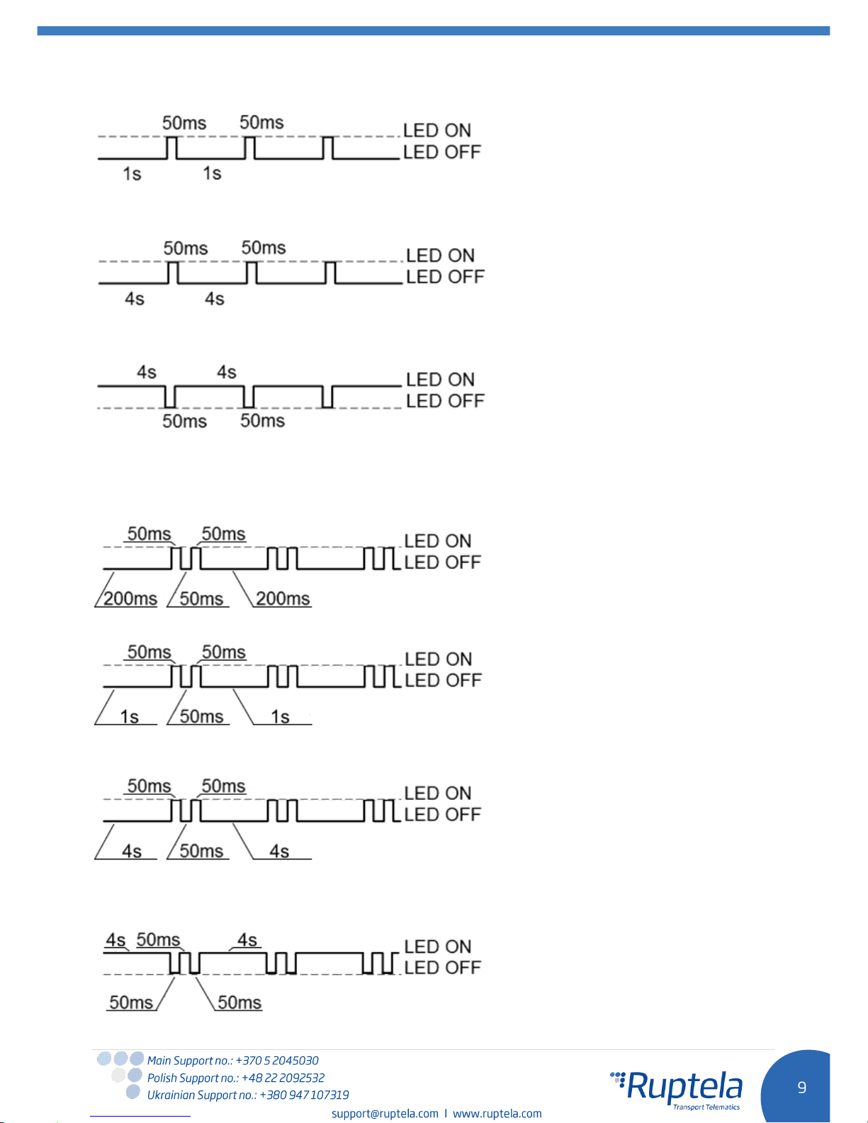
When device has a good GSM signal, but no GPRS, the LED is blinking as follows:
When device acquires a good GSM signal and is connected to GPRS, then the LED is blinking as
follows:
When the FM-Plug4/4+ terminal acquires a GSM signal and is sending data via GPRS, the LED is on
while sending data:
3.8.2 LED when GNSS fix is not acquired
When GSM signal is not received, the LED blinks as follows:
When device has a good GSM signal, but no GPRS, the LED is blinking as follows:
When device acquires a good GSM signal and is connected to GPRS, then the LED is blinking as
follows:
When the FM-Plug4/4+ terminal acquires a GSM signal and is sending data via GPRS, the LED is on
while sending data:
Page 11
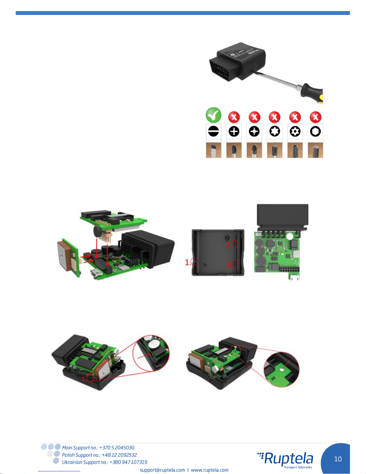
4 Device preparation
In order for the device to work you have to configure it
and insert a SIM card. To do so, you have to open the
device’s enclosure. It has no screws, the top part can be
easily removed using screw driver or similar tool (
see
figure on the right
).
4.1 Opening/Closing the device
Use a screwdriver or a similar tool to open up the plastic
housing of the device. It is recommended to use a “slot”
type screwdriver (
see figure on the right
). Inappropriate
tools might cause permanent damage to the device.
FM-Plug4/4+ PCB is made out of 3 smaller PCB’s parts. The main PCB with the OBD connector is at the
bottom. PCB with the GSM modem and antenna is at the top. PCB with the GPS/GLONASS module and
antenna is on the left side. These parts must be joined together (
see figure below
) before placing them
into the plastic housing.
To correctly assemble the device you have to know the exact positions of all the plastic pins used to
hold the PCB in place (
see below
).
Proper assembly sequence:
1. The bottom part of the fully assembled PCB goes under the plastic pin 1 (
see below
).
2. The other side of the PCB is pressed down under the plastic pins 2 and 3 until you hear a
“click” sound, which indicates that the PCB is locked in its place.
3. Finally use a small screw to fasten the PCB (
see below
).
To
correc
tly
seal the plastic housing of the device, start by placing the plastic lid at either side of the device (
see
figure below
). Then push the remaining side down until the housing is fully closed.
Page 12
Note
It is recommended to keep the number of opening procedures to the minimum.
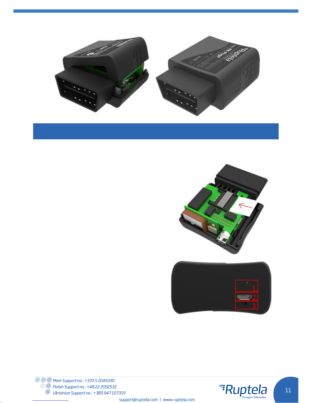
4.2 Inserting a SIM card
If you received a device without a SIM card, place your
own SIM card into the device as shown in the picture
below. The microchip must be facing down.
4.3 Connecting the USB cable
Device - PC connection is done via USB A to micro
USB B cable. The device has a micro USB socket
[2.] (
See figure on the right)
. The cable can be
connected only in one way, be careful not to
damage the plug. Connect the other end to your
PC or a laptop. Configuration can be done without
external power supply - for the configuration the
device can be powered from the USB.
[1.] Microphone; [3.] LED.
Page 13
5 Device configuration
5.1 Driver installation
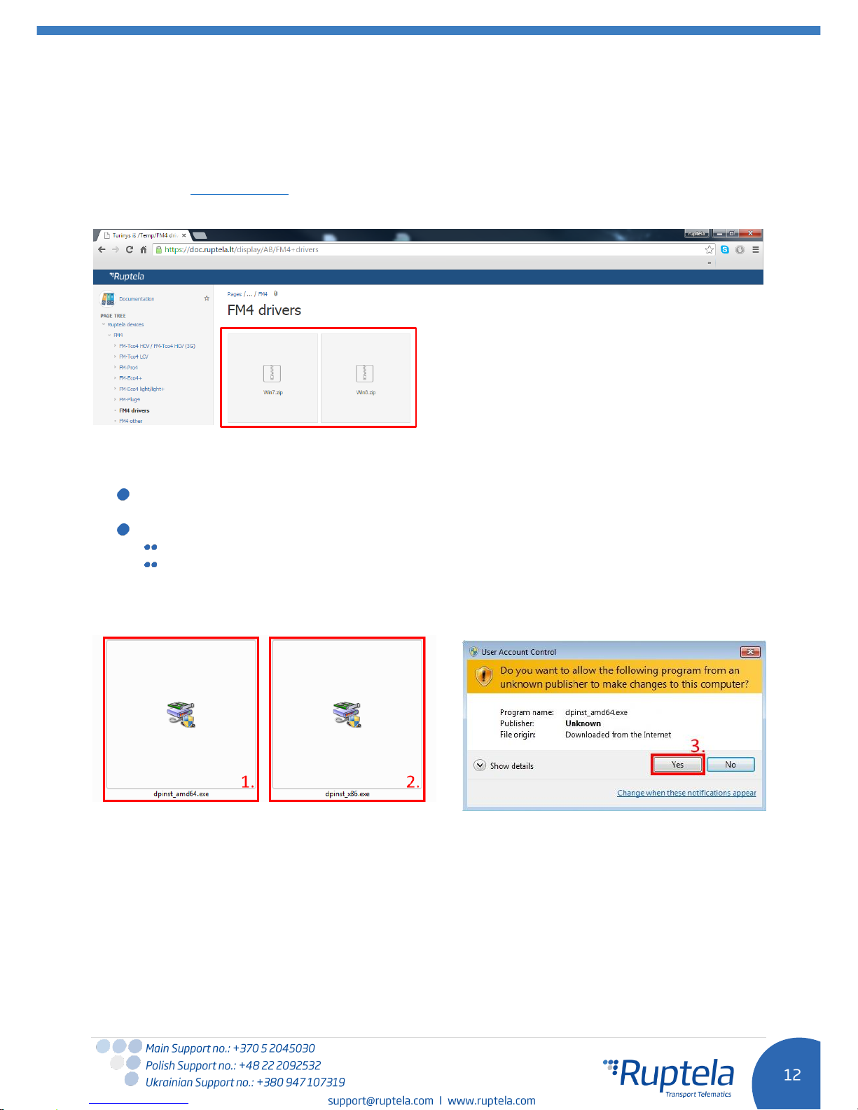
Virtual COM port driver installation is mandatory, only then your PC will recognize the FM-Eco4 light
device that was connected to the USB port. You can download the latest driver from our documentation
website server (VCOM drivers).
Choose correct archive file with drivers for your OS version and download it to your PC.
Installation procedure:
Uninstall previous Virtual COM port driver versions (Start-> Settings-> Control Panel-> Add or
remove programs).
Extract archive file “Win7.zip” or “Win8.zip” to a desired location on your PC.
If you are running a 32-bits OS version, launch the “dpinst_x86.exe” [1.]
If you are running a 64-bits OS version, launch the “dpinst_amd64.exe” [2.]
Windows 7 Users might get a Security Warning message. Click “Yes” [3.].
Page 14
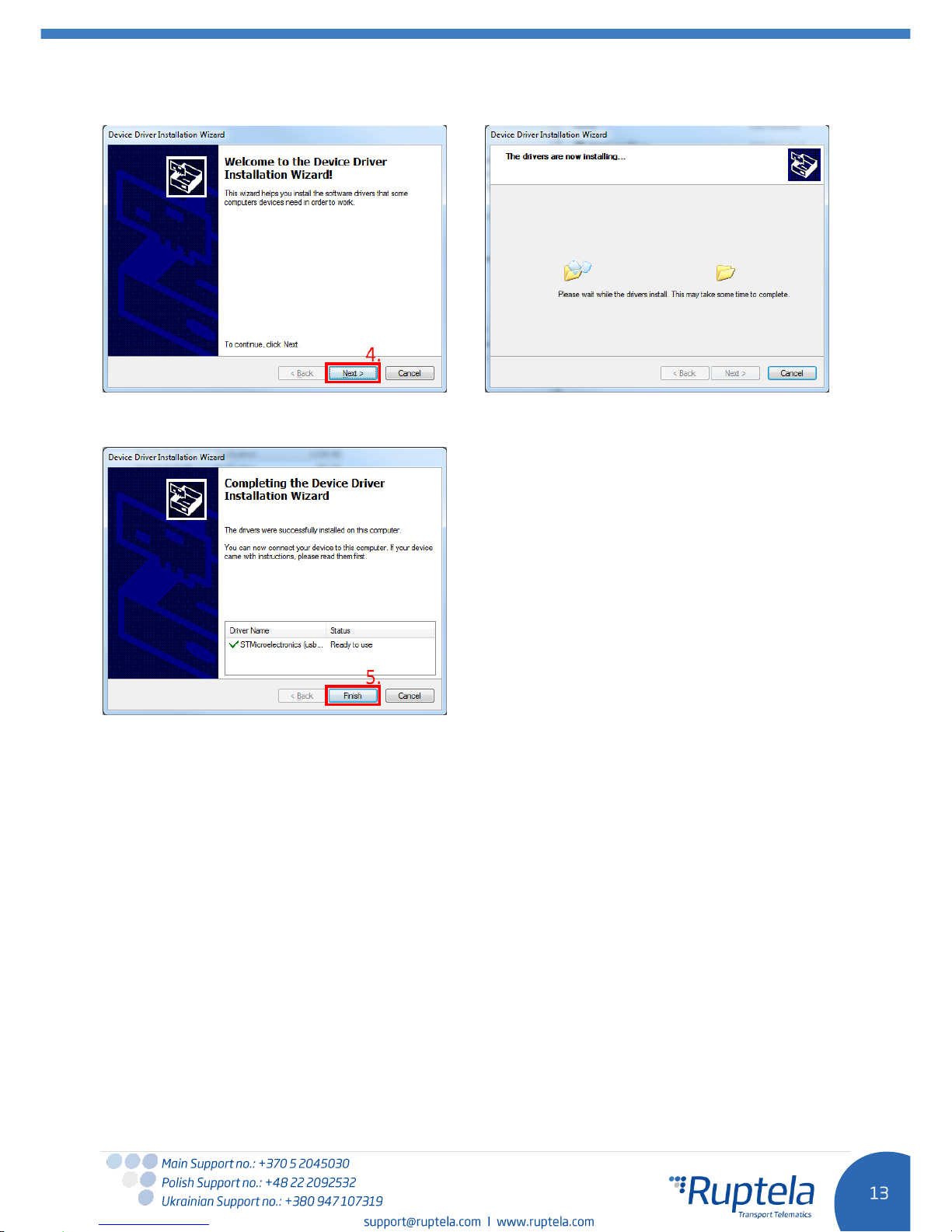
In the next window select “Next” [4.].
Wait for the setup to complete the installation and click “Finish” [5.].
Driver is now installed and ready to use.
Page 15
5.2 Sample configuration
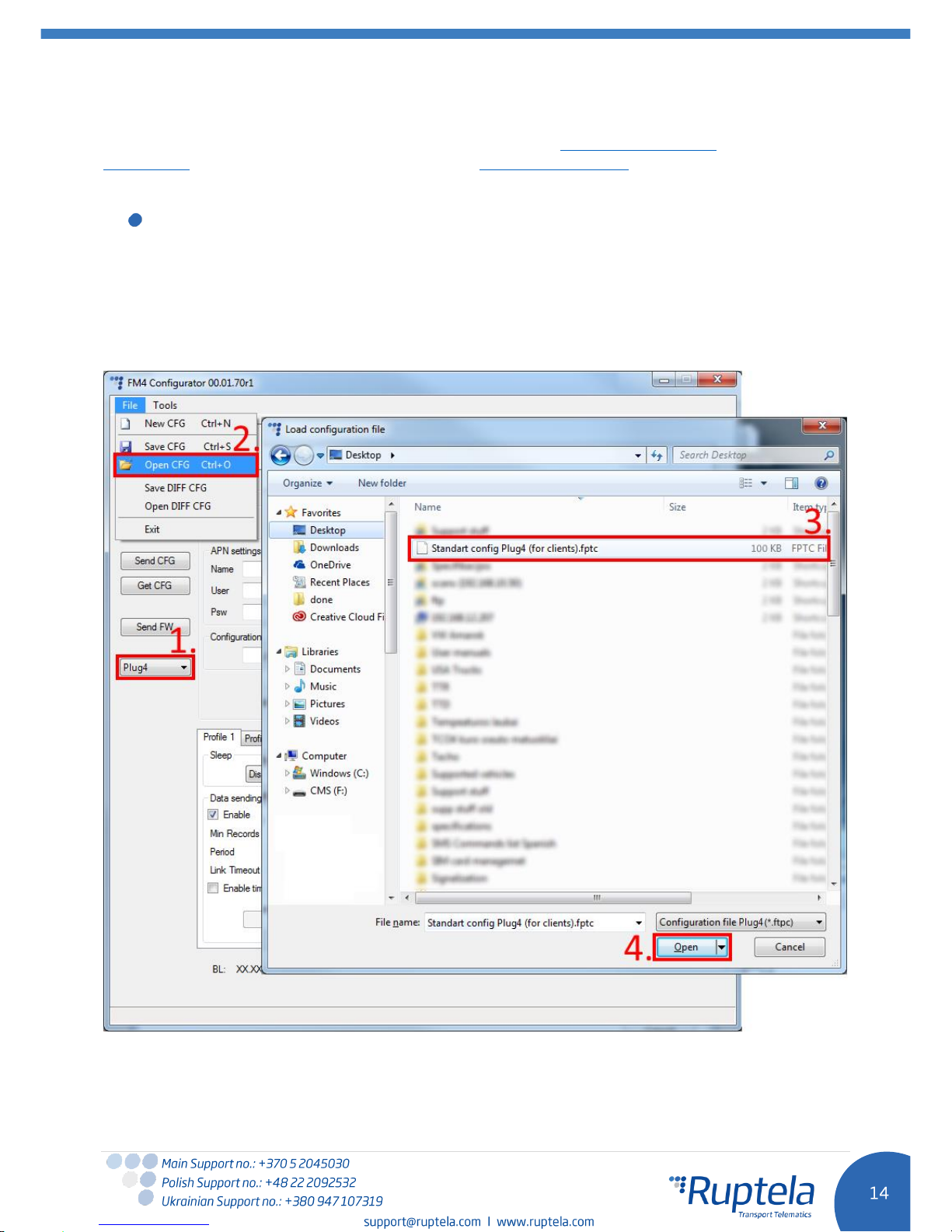
Go to our documentation website server and download sample configuration and the latest
configurator. Also you will need the latest version of Microsoft Framework.
Operating system requirements:
MS Windows XP/Vista/7/8/10
Start VCP.exe from configurator folder.
1. Select Plug4
2. Click File → Open CFG
3. In the dialog window, browse the sample configuration file that you have downloaded from the
documentation website.
4. Click Open
Sample parameters will be loaded. However you will need to enter other parameters on your own.
1. Enter IP (in the 255.255.255.255 format) or a Domain Name (not exceeding 40 characters) and
PORT to which the device should send data.
Page 16
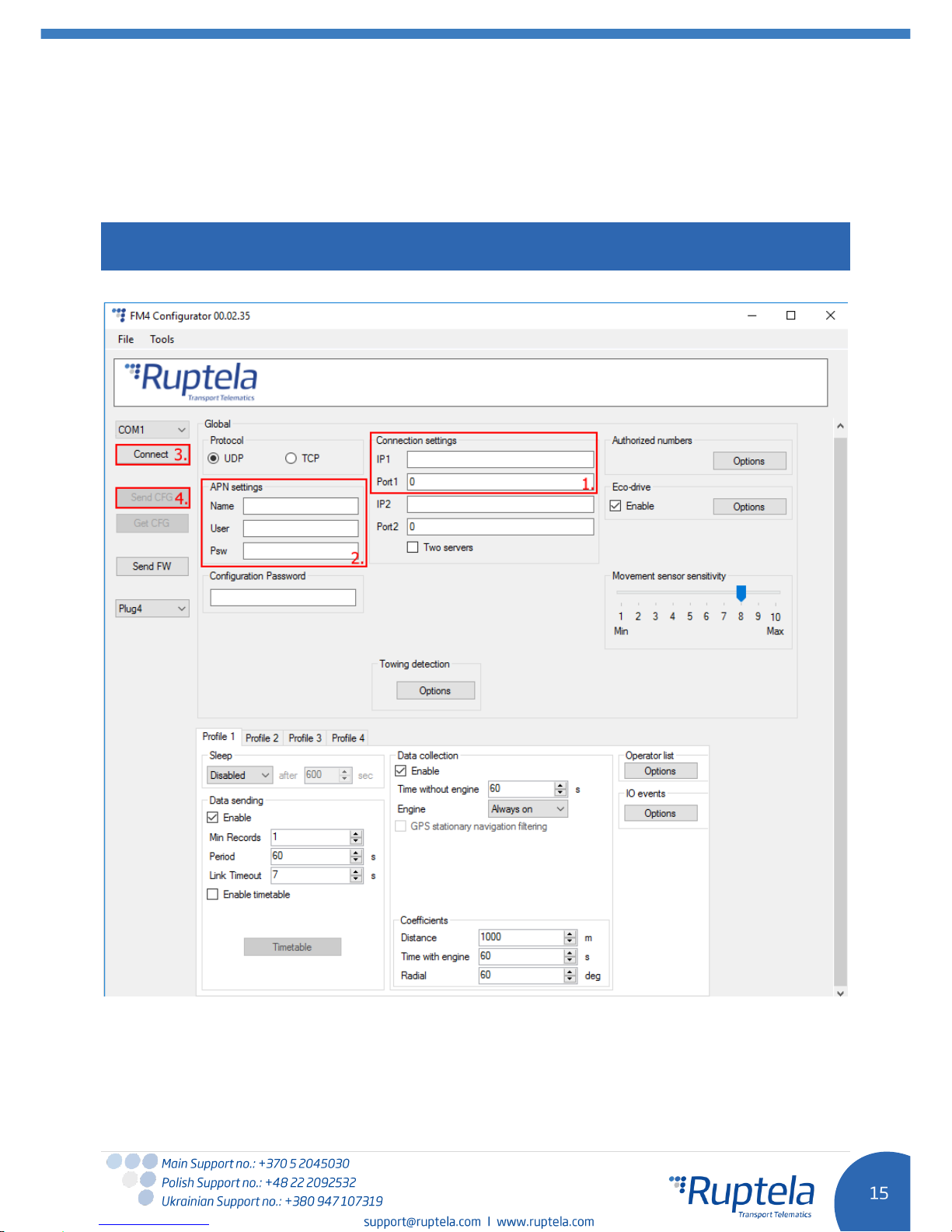
2. Enter APN settings: APN name, User login and Password (if login and password needed).
3. Select a COM port you connected the device to and click Connect. At this point the configuration
is ready to be send to the device, so the device must be connected to the computer.
4. Click Send CFG button. The configuration will be uploaded to the device.
Note
APN name, login and password should be provided by your mobile network operator
Now the device is configured to send data to the specific server. Sample IO parameters are enabled
(loaded with configuration file). You can log in to your tracking platform to see whether the device is
sending data.
Page 17
5.3 Advanced configuration
The configuration tool is quite similar to the ones used
for other 4th generation devices. Overview of the
configuration is described in sections.
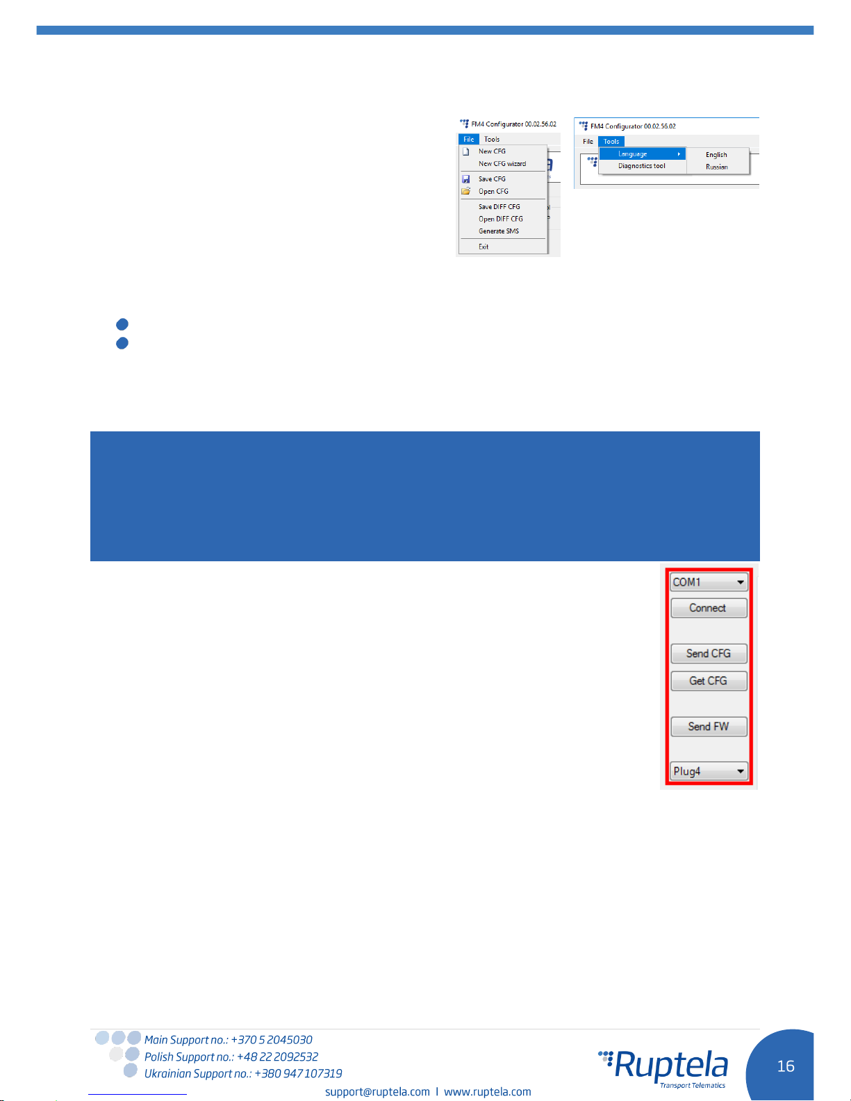
The “File” menu gives you access to control
configuration files. Choose
New/Save/Open CFG
to
perform the corresponding action. CFG means full
configuration file.
New CFG wizard – It helps users to go through all basic configuration steps.
The “Tools” menu contains:
Language selection options: English or Russian are available.
Diagnostics tool.
Save/Open DIFF
allows you to create a DIFF file. DIFF files are used to change only one or few certain
parameters without a need to upload the full configuration to the device. It is useful, when updating
over-the-air.
Attention
A DIFF file will save all made changes to a configuration. For example changing a number in the IP
filed, or marking a checkbox, but, if a change was made, and afterwards reverted to the previous state
(checkbox checked, and unchecked afterwards), this will not be marked as a "change made". DIFF will
only record changes made to the initial configuration (a loaded pre-set configuration is considered an
initial configuration). Particular attention must be taken, when creating a DIFF file, to avoid accidental
changes to the configuration.
The control panel on the left hand side allows you to choose and control the device.
Select the “COM” port that the device is connected to and hit “Connect”. At this
point FM4 configurator checks compatibility between itself and firmware (FW) in the
device. Every FW version is released together with a recommended FM4
configurator. More information about different FW’s and recommended configurators
for them can be found in FW changelogs. After compatibility check, three outcomes
are possible:
1. FW and FM4 configurator versions are compatible. Go ahead and continue FM
device configuration.
2. FW is incompatible with this FM4 configurator, because FW version is too old
for this configurator. This will be notified in a new alert pop up window. “Send
CFG” and “Get CFG” buttons will be disabled. Use “Send FW” button to update
firmware version in the device.
3. FW is incompatible with this FM4 configurator, because configurator is too old for this FW
version. This will be notified in a new alert pop up window. Download new version of FM4
configurator, which is recommended for this firmware version.
“Send CFG” and “Get CFG” buttons are used to send and receive the configuration file to/from the
hardware.
“Send FW” is used to send new firmware to your device.
In the drop box below you can select a type of the device.
Page 18
5.3.1 Global settings
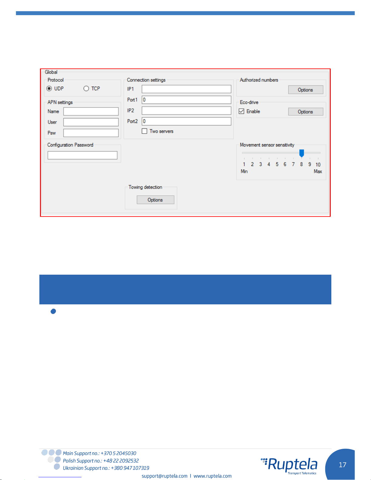
The first part of the configuration tool is “Global” settings. Global include connection settings and other
settings independent from the profile settings – global settings are the same for all profiles.
Connection settings here you should enter server IP and port that the device should connect to. The
IP can be entered in the numeric format: 255.255.255.255. You can also use a Domain name (not
exceeding 40 characters). IP 2 is a backup IP address, which is used when the device is unable to
connect to the first server.
Note
Please have in mind that ports for TCP and UDP transfer protocols usually are different – please select
the correct transfer protocol and enter the correct port.
Two servers – checkbox changes the logic described above. It enables a two servers mode –
the same data is repeatedly transmitted to another server with IP2, unless we get a timeout. IP1
is dedicated IP for server, from which we get the ACK’s for our record packets sent. After we get
the ACK from this IP, record data is considered as successfully transmitted to the server and it is
removed from the memory.
In this mode data is sent to IP2 only when connection to the IP1 is established. Packet, which is
sent to the IP1 server is also sent to the IP2 server.
Only records are going to be send to the IP2. Data packets such as Transparent Channel,
Tachograph, SD card, Garmin will not be send to the IP2.
Unable to send data:
When unable to establish connection to IP1, device does not connect to the IP2 as well. When
connected to IP1 and doing data transmission, but IP2 is unreachable – after receiving ACK from
IP1 server, data is removed from memory, which can cause information loss in IP2 server.
Page 19
Note
Two server mode doubles the amount of data that is being sent. Before using this functionality
consider the cost which arises from the higher data traffic.
Starting with the version FM-Plug4 00.01.04.00 geofencing feature is removed, however bug fixing will
be available. Recommended FM4 Configurator 00.02.20 for this firmware version does not permit
firmware downgrades.
Note
Older firmware versions also including the FM-Plug4 00.01.03.02 are no longer supported. If any bugs
are found in these firmwares, they will not be fixed.
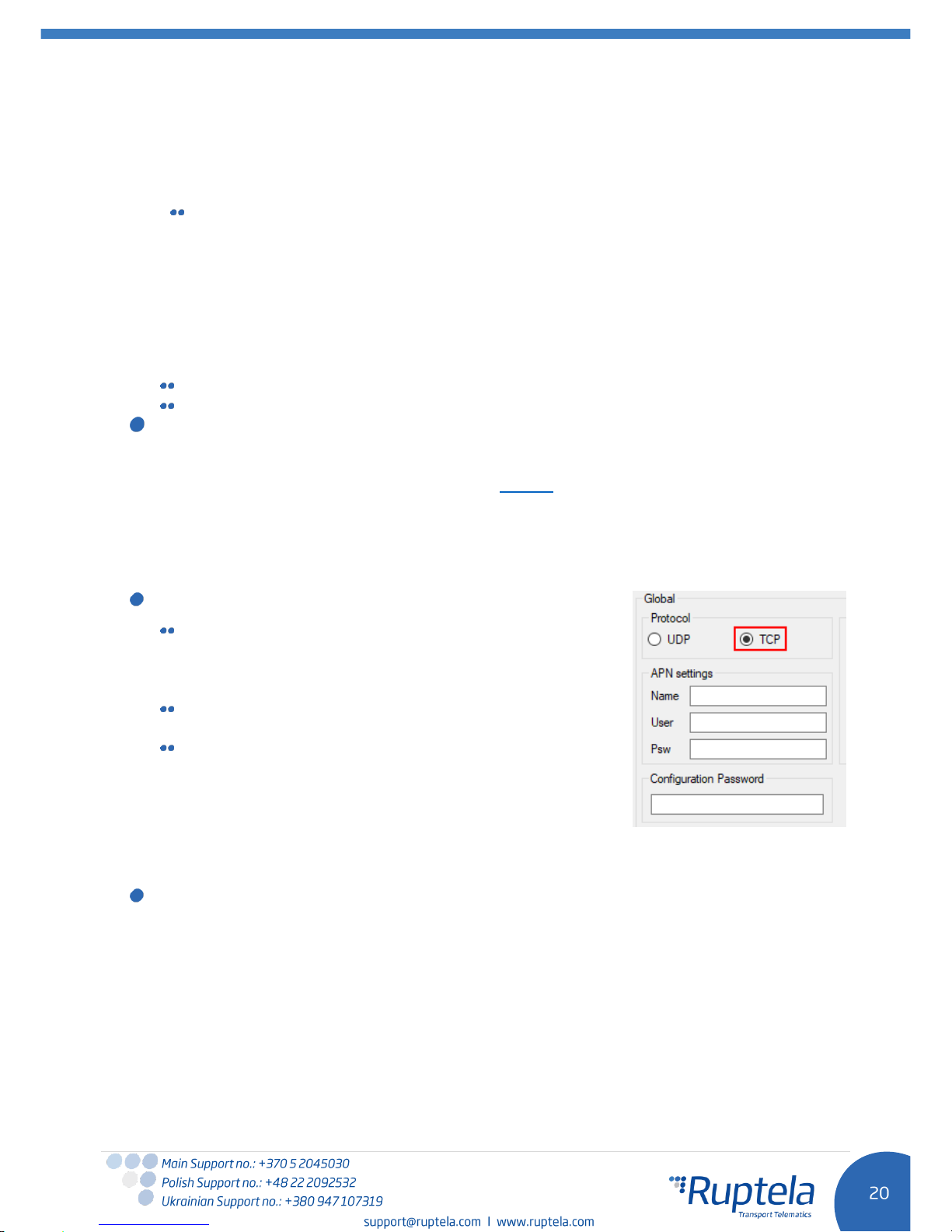
Protocol sections allows you to choose from two protocols. UDP protocol is less reliable than the TCP,
but also uses less traffic. TCP uses more internet traffic, but it is more reliable. Choose one according to
your needs.
Note
If the IP, port or APN fields are greyed out when the device is connected to the configurator, their
values cannot be changed.
APN settings are needed for internet connection. These settings must be provided by your mobile
network provider. Without APN settings the device will not send any data.
Configuration password allows to lock the configuration – without the password no one can change
the device configuration via cable. However, over-the-air update ignores the configuration password.
Send data without GPS fix – This function is limited to the GSM tracking function. The “Send data
without GPS fix” function is disabled for the FM-Plug4 device. When the device loses GPS fix, there is no
way to determine its location. GSM tracking feature can now be used to obtain an approximate location
in the densely urbanized areas, where GPS signal is not available. This feature cannot be used with
TrustTrack server! Full functionality description can be found in “Send data without GPS fix” document
on our documentation website.
Towing detection - with Towing detection driver can be informed, that his car is being towed.
Information about such event is sent to the server, therefore driver might still have time to come back
to his vehicle before it is taken away. Full functionality description
can be found on our documentation website.
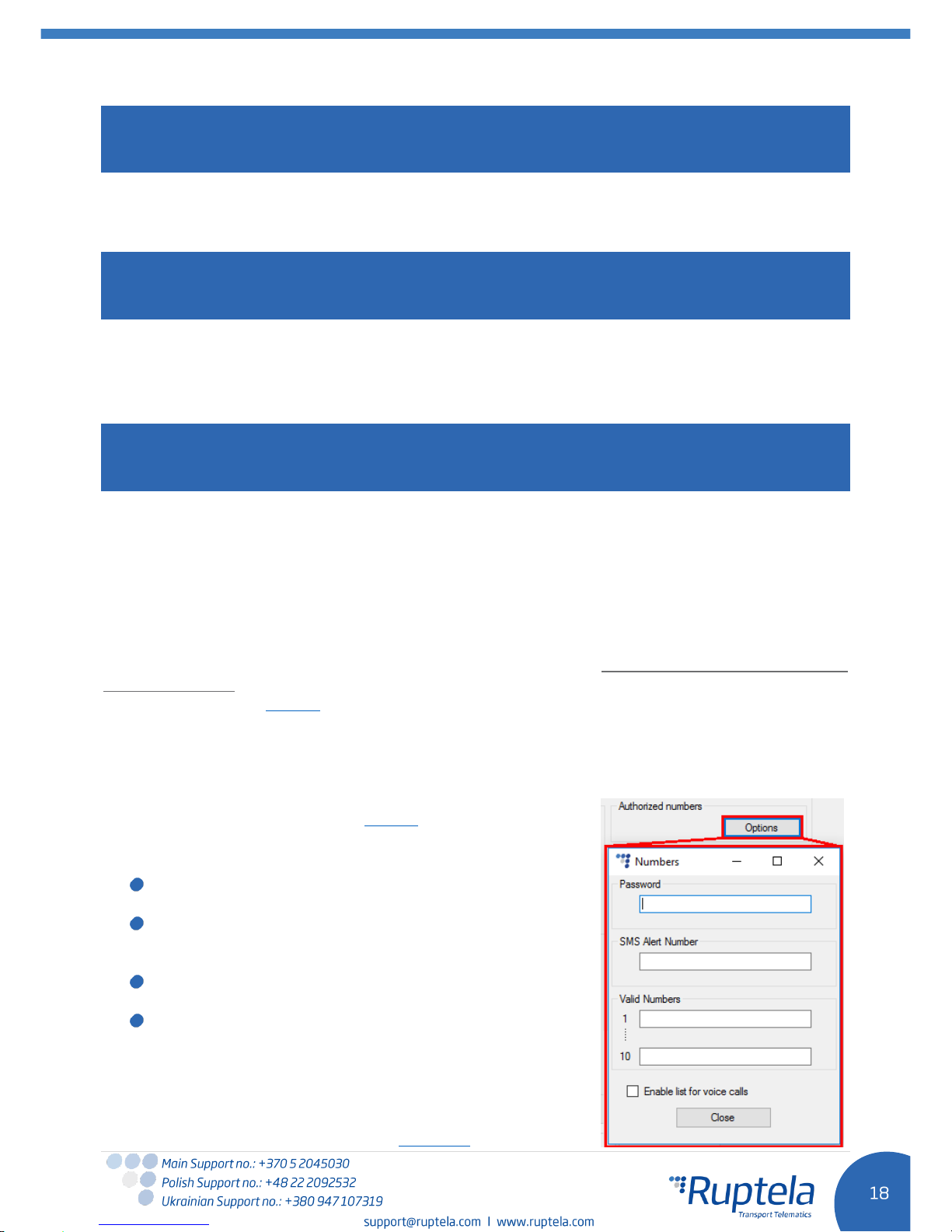
Authorized numbers
Set a Password to restrict access to the SMS commands
feature.
SMS Alert Number. When specific I/O parameter is
triggered, the FM device will send an alert message to this
number.
In the Valid Numbers table enter specific numbers that
will be able to send commands to the device.
If you check Enable list for voice calls entered numbers
will be able to make a call to the device.
ECO Driving options are used to choose sensitivity for the ECO
Drive functionality. It helps to rate drivers according to their safety
or according to driver's behavior. Full functionality description can
be found on our documentation website, ECO Drive.
Page 20
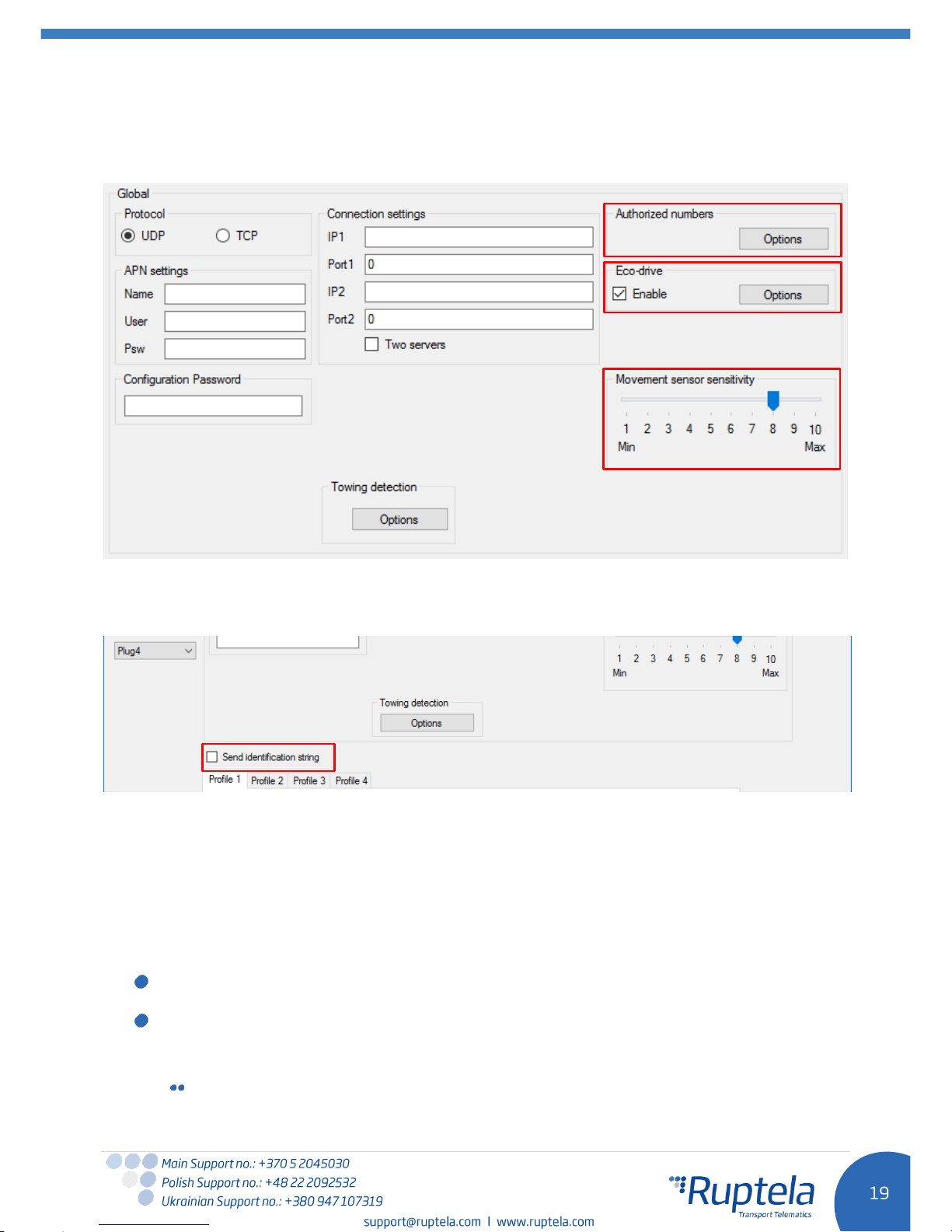
Movement sensor sensitivity allows you to configure movement sensor according to your needs. If
you slide the bar towards the Max, the sensor will detect even very slight movements. If you slide it to
the Min, than only stronger movements will be detected.
Send identification string feature forces FM device to send an identification packet to the server.
After that the device waits for the ACK packet from the server. Once device receives this packet, it
begins data transfer.
5.3.2 Profile settings
The second part of the configuration tool is for profile settings. This section also contain explanations
for other features that needs extensive configuration. Functionalities descriptions are available.
Each “Profile” is a settings set for specific circumstances (e.g. One profile for the vehicle, when it is
operated in the native country and another profile, when it is abroad).
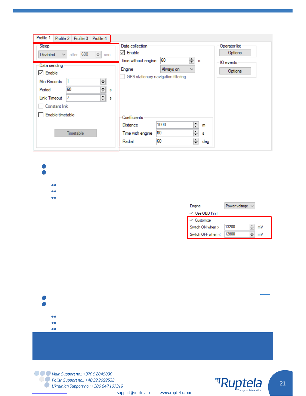
Sleep can be
Disabled
,
Deep sleep or Custom
.
“Disabled” – the device never goes to the Deep sleep mode and is working as long as there is
power.
“Deep sleep” – device’s ability to go to the Deep sleep mode depends on the ignition detection
settings (ignition detection settings are reviewed below, under the Data collection section,
where the Engine drop box values are described):
If “Always on” or “Power voltage” is selected in the Engine drop box, then the device will
never enter the Deep sleep mode. As soon as the ignition is turned off in the vehicle, the
Page 21
voltage level at the OBD2 Pin 16 will drop to zero and the device will shut down
immediately.
(In some older vehicle models the voltage level at the OBD Pin 16 drops below 13 V, but
not to 0 V. In such cases the device will enter the Deep sleep mode, after a certain
amount of time have passed, usually this takes 10 minutes).
If “MovSensor” is selected in the Engine drop box, then the device can enter the Deep
sleep mode. This will happen when the vehicle spends enough time idling (not moving)
with the ignition on/engine running. In this case the ignition will be considered to be off,
but since there is still power in the OBD, the device will enter the Deep sleep mode, after a
certain amount of time have passed, usually this takes 10 minutes.
Deep sleep extends internal battery life by turning off GNSS/GSM modules and all internal
interfaces to the car BUSes.
The device will wake up from the Deep sleep mode when these conditions are met:
Movement sensor detects movement.
Voltage level is higher than 13 V.
When “
Custom”
is selected you can choose, which functionalities should work during device
sleep and which functionalities should be disabled. Like previously, it possible to set a time limit.
Once this time limit is reached, the device will switch to Custom sleep mode. Full functionality
description can be found on our documentation website.
With Data sending settings you can configure the data sending frequency and conditions.
The Enable check box must be enabled.
Min. records – Minimum number of records required to
establish a connection to the server. If the device detects
less records than entered value, link to the server will not be
opened.
Period – sets how often the device will check for required
number of records.
Link timeout – this value indicates how long the device
should wait before closing the link, after this link was
successfully established with the server and all the records
had been sent. The default value is 7 seconds, it is
recommended not to change it.
Timetable allows you to select particular days and hours for the data to be sent.
Page 22
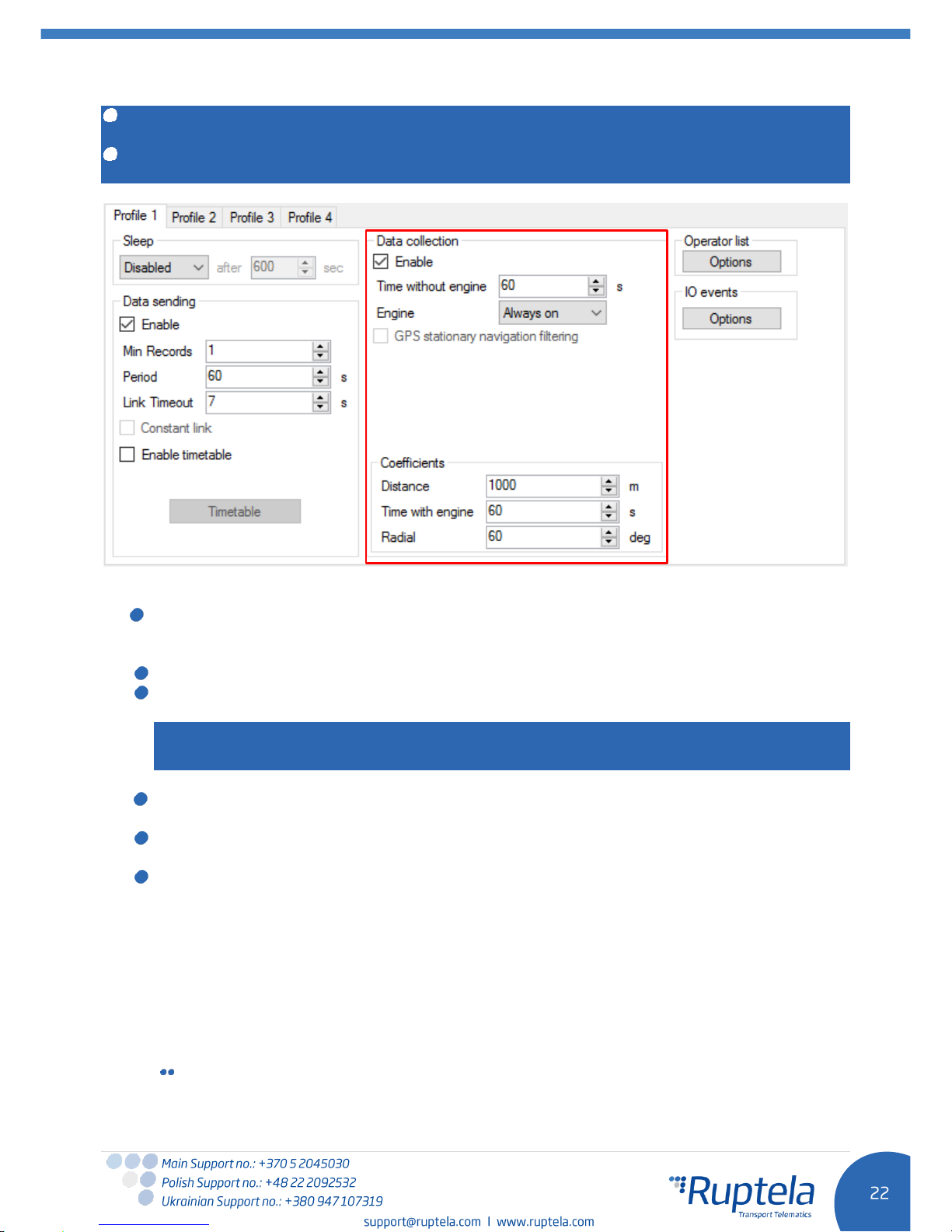
Data collection must be enabled to collect the information.
Time without engine means how often records should be made, when the engine is off.
Engine drop box allows you to choose how the device will pick up the ignition (consider that the
engine is on).
Always on
– No ignition pick up, engine considered always to be on.
MovSensor
– Detect moving of vehicle and consider engine to be on.
Power voltage
– Voltage in the Pin 16 of the OBD2 connector is used for the ignition pick up.
o There is also a possibility to set custom power
supply voltage thresholds for virtual ignition. Both
voltage thresholds for switching virtual ignition ON
and OFF are configurable. In order to enable this
feature put a tick on Customize checkbox.
Default value in Switch ON when > field is
13200 mV. Range from 0 to 40000 mV.
Default value in Switch OFF when < field is 12800 mV. Range from 0 to 40000 mV.
Example. 13200 mV value is configured to switch the ignition ON. In this case, if voltage
level in the OBD Pin 16 is equal or higher than 13201 mV, the engine will be considered
to be on.
o In some cases users might experience problems with an engine state detection. If
custom voltage ranges for engine detection are not suitable and they need a plug and
play solution, they can rely on an automatic engine state detection functionality. This
feature is described in “Automatic engine detection” document, which can be found here.
GPS stationary navigation filtering eliminates GPS jumps, when the vehicle is not moving.
Coefficients are used to collect records in addition to the engine on/off parameters. A record
will be made when:
Distance that was set - has been achieved
Time with engine has passed
Radial turn of degrees that was entered - has been detected.
Note
Keep in mind that FM Device is not designed to have a perfectly accurate time tracking function. Due to
various reasons minimal deviations are possible. Over prolonged time periods these small deviations
might add up and produce time tracking inaccuracies. Few examples:
Page 23
Device is configured to track one event for 1h. However actual event tracking might last for 1h ±
Error (i.e. 5 seconds).
Device is configured to gather records every second. Depending on the device’s state, record
gathering time might deviate and last longer (i.e. 2, 3 or even 5 seconds).
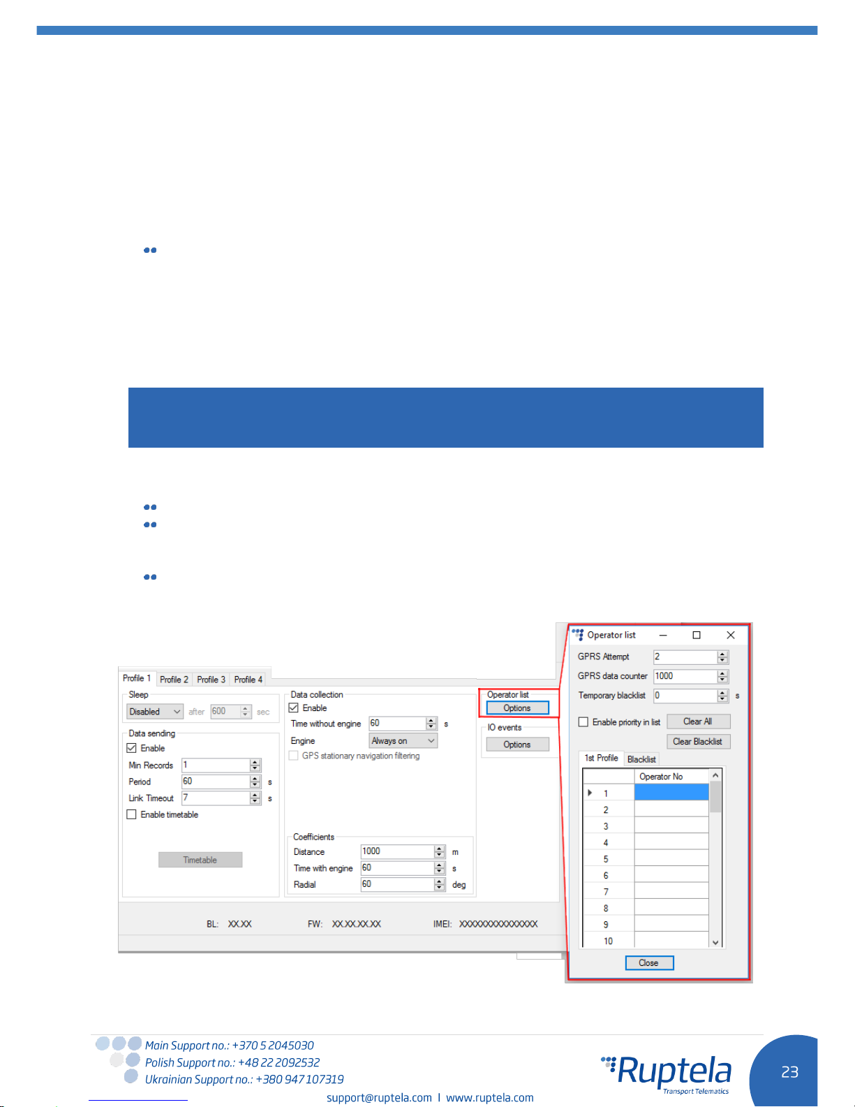
Operator list
1
st
… 3rd Profile tab – operators list in this tab allows selection of operators used in current
profile. If operator that is in the list was not found, then device will search for other operator in
the list. If no operators were found, device will switch to the next profile.
Blacklist has opposite meaning for operator list. Operators that are in blacklist will not joined.
Enable priority in list - search for operators according to number in list. If it is not selected,
device will search for operator randomly.
Note
Black list is one for all profiles, but operator lists are different for each profile.
GPRS Attempt – how many times device will try to attach to operator`s GPRS before trying
another operator.
GPRS data counter – how many kilobytes of data device should send before performing next
operator search.
Temporary blacklist – temporal ban period in seconds. Sometimes when the FM device
connects to the operator with unavailable GPRS, the device is connected, but cannot transmit
any data to the server. In such case temporary blacklist is used. Operator with unavailable GPRS
gets into the temporary blacklist, which prevents the FM device’s connection to this operator on
the next operator search.
In other case, device connects to mobile operator and successfully obtains GSM and GPRS
signal. However, records still do not reach the server. Device has an ability to work around the
faulty network (i.e. when network connection is lost) by putting this operator into the temporary
backlist. Ban in this case is implemented via 2nd level temporary black list logic. Network
verification is done as follows:
Server pinging – device performs server pinging only when there is no response (no ACK)
from the server and if the connection to server is not available.
Page 24
It will make up to 3 separate pinging attempts. If any of these attempts are successful,
network will be verified. In an ideal case, server responds after the first attempt, network is
verified and no more pinging operations are needed.
If the server fails to respond to all of them, the device will switch to another operator, after
putting current operator into the temporary black list.
During a single pinging operation device transmits approximately 256 bytes of data. If
device needs to make all three attempts, it will send approximately 768 bytes.
Operator is also added to the temporary black list, when the device receives "13110" error
code from the operator. According to Quectel M95 AT command manual the first number in
error code “1” stands for “Cause for protocol stack (PS) layer” and the rest “3110” stands
for "Network fail".
Received trouble codes can be monitored with the help of "GSM trouble codes" IO
parameter.
Note
This functionality might be compatible and might be supported with 3G modems used in Ruptela's
FM devices.
Key point about the temporary black list:
Ban period is configurable. When all operators get into the ban list, ban list is cleared.
Banned means that the terminal was not able to get the GPRS context, it was unable to
connect to the operator, server failed to respond to 3 consecutive ping requests or that the
terminal received "3110" error code from the mobile operator.
Ban list is in the RAM the memory, it is cleared after reset or power off.
Page 25
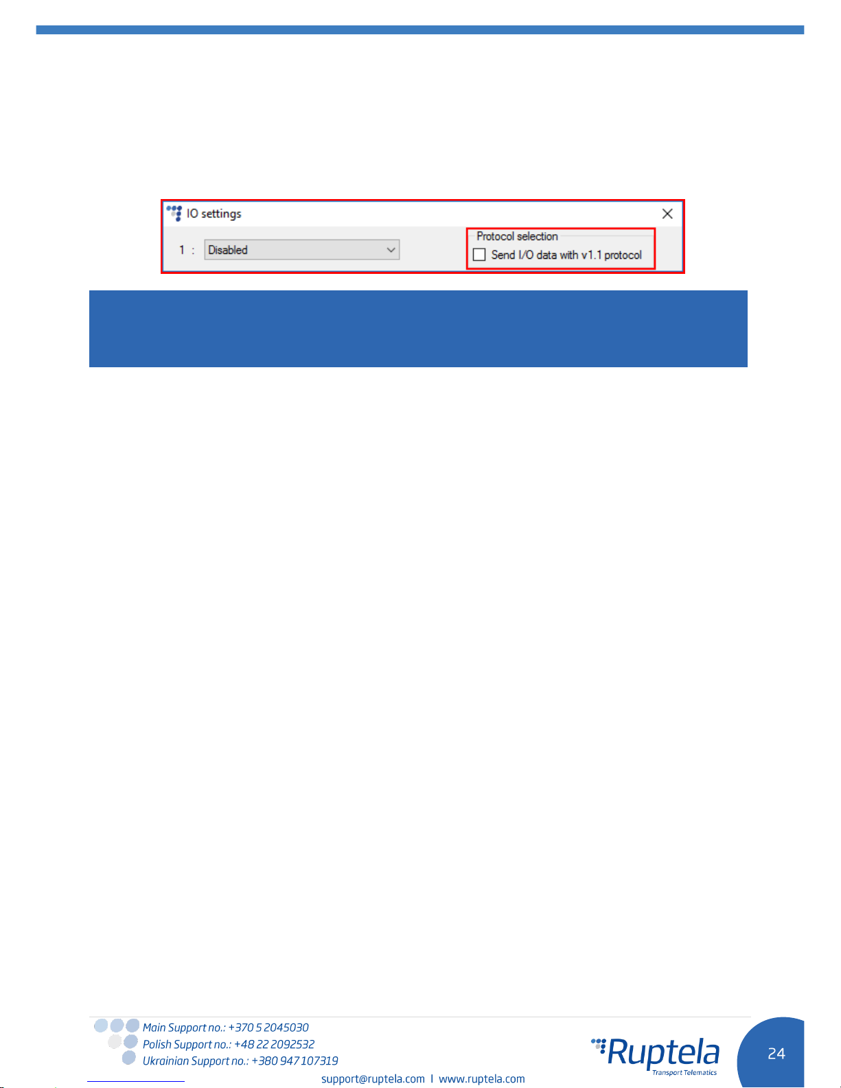
5.3.3 IO settings
IO events “Options” buttons opens up a new “IO settings” window, here you can enable or disable IO
parameters that will be sent to a server. The setting the user should configure, is the protocol selection.
Protocol selection section has a checkbox, where you can choose to “Send I/O data with v1.1
protocol”.
Note
A significant part of the IO parameters require that the protocol v1.1 is enabled! Without it enabled,
these parameters will not be displayed in the ID list. Enabling the protocol will delete all unsent records
from the device.
After the user decided on the protocol settings in accordance with his needs, he can move on to the IO
parameters. There are several ways to enable IO parameters, the first way described is the fully manual
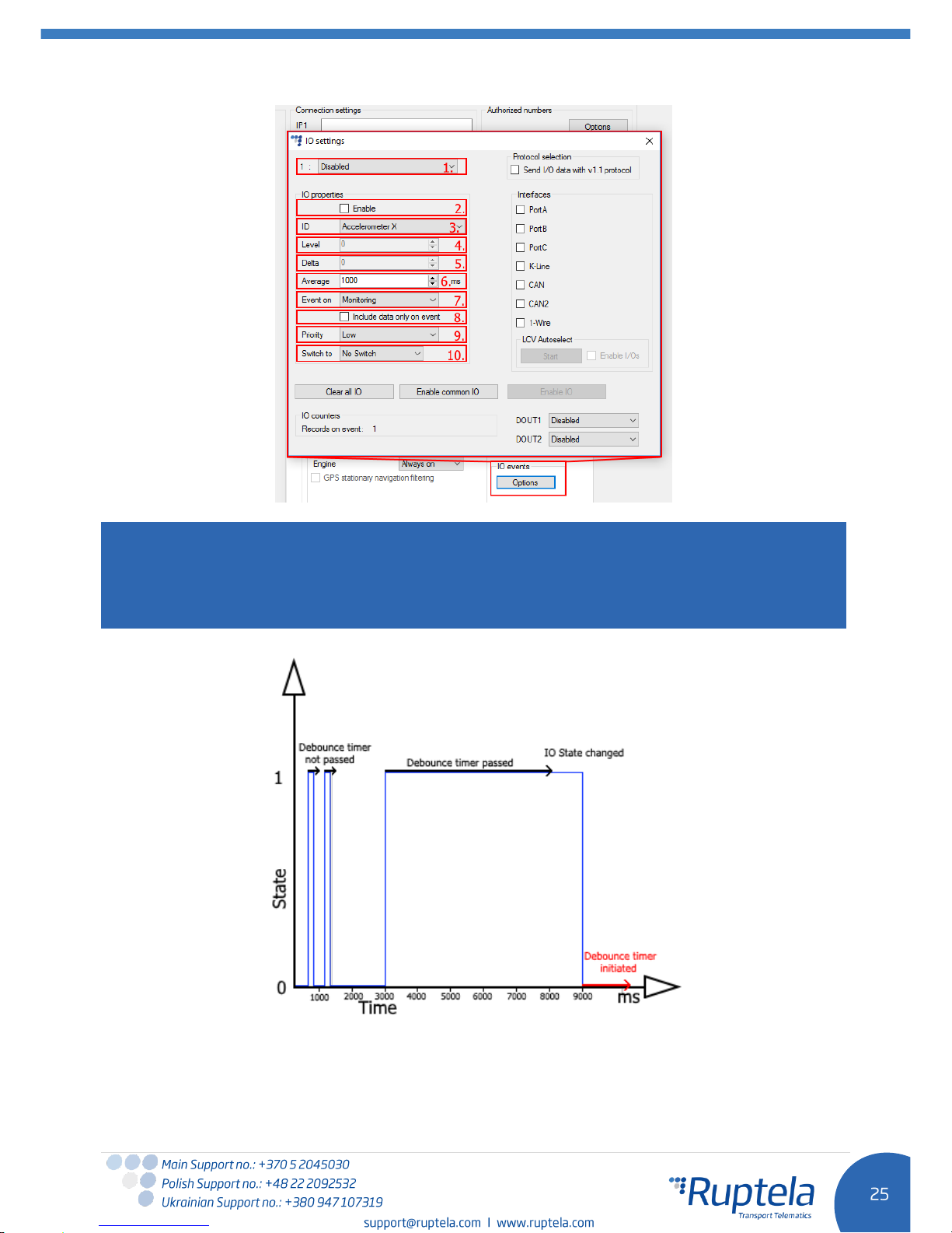
way, where the user enables and configures each IO by hand:
1. You have 40 slots for parameters. Select slot you want to enable.
2. In the IO properties section tick the Enable check box, otherwise the slot will remain empty.
3. ID contains the parameter list. Choose a parameter you want to enable for the selected slot. One
parameter can be enabled only one time.
4. Level is used with hysteresis mode,
see 7.c below for more details.
5. Delta is used with hysteresis mode,
see 7.c below for more details.
6. Average. Some parameter`s values change rapidly and do not correspond any valuable
information. Averaging values for some period of time gives a more usable value of the parameter
(e.g. fuel level often oscillates. Averaging gives you an approximated value that correspond to the
real fuel level in the tank).
7. Event on – describes how the parameter will be measured and sent:
a.
Monitoring
– Parameter value is always monitored and sent with every record
b.
Change
– when value is changed record will be made regarding this change. However
parameter is monitored and sent to server with every record
c.
Hysteresis
– Record is generated because of specified change in parameter value. E.g.
parameter is Power Supply voltage. Level sets point of reference, in this case 12700 mV. Delta
is variation in value, e.g. 1000 mV. Record will be generated (because of parameter value
change) when Power supply voltage drops to < 11700 mV and/or > 13700 mV. You can select
condition “on rising” or “on falling”
8. Select Include data only on event to get a parameter value only when the condition (set in step
7) is met. In other cases the parameter value will not be included in the records.
9. If Priority is set to “High”, the record will be sent immediately, disregarding data sending settings.
If it is “Low”, the device will wait for suitable conditions to open a link to server.
10. Upon an event of a value change in some parameter you can configure the device to Switch to
the other profile.
Page 26
Note
Some IOs will have a "Debounce" setting instead of the "Average" setting. Debounce defines for how
long the device must receive a changed state of an IO, before it registers the changed state. For
example, the DIN state changed from 0 to 1 and Debounce is set to 5000ms, so the signal from the
DIN must remain constant for the period of 5000ms to actually change the state of the IO from 0 to 1.
If IOs were configured incorrectly, or the user simply decides to re-do the configuration, he can use the
“Clear all IO” button, which disables all the enabled IOs along with their configuration in the selected
profile.
Page 27
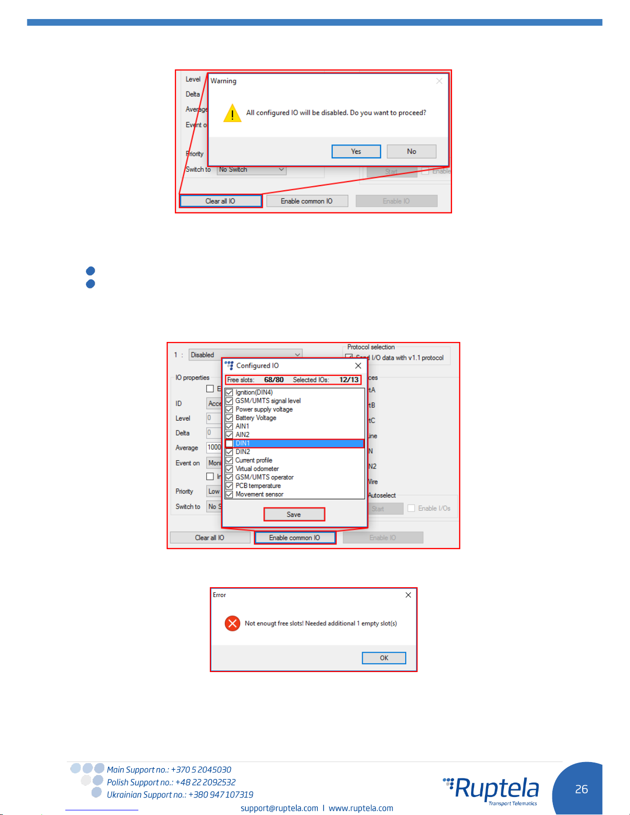
The next method describes how to automatically enable and configure commonly used IOs. To do this,
the user must simply click the “Enable common IO” button. This will open a window with a list of IO
parameters that will be enabled along with additional information, such as:
Free IO slots remaining after the selected IOs are enabled;
Amount of IO parameters selected.
The user can also choose, which of the IO parameters to enable, this can be done by unchecking the
checkbox before the IO parameter name. To enable the selected parameters, the user must click
“Save”.
If there are not enough slots to enable the selected IO parameters, an error window will appear.
Lastly, the “Enable IO” button enables IOs for the selected interfaces. This button is available only
if the “Protocol v1.1” is enabled!
Page 28
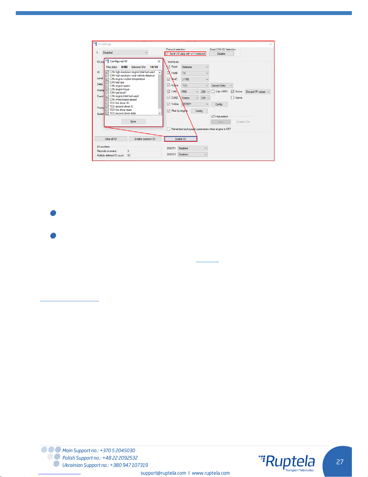
Interfaces are described further down in this document.
Interfaces section gives ability to enable or disable all of the device’s interfaces. Bellow you will find
checkboxes for the K-Line and CAN interfaces.
K-Line – if you put a tick in the K-Line checkbox, then a windows will appear where you can choose:
DTC enable - here you can specify Diagnostic Trouble Codes reading interval in minutes. Below
two additional checkboxes are displayed, meant to specify Fuel type:
“Gasoline”, “Diesel”.
CAN – if you put a tick in the CAN interface checkbox, a windows will appear where you can choose:
DTC enable - here you can specify Diagnostic Trouble Codes reading interval in minutes. Below
two additional checkboxes are displayed, meant to specify Fuel type:
“Gasoline”, “Diesel”.
More information available at our on our documentation website.
5.4 Integration protocol
All integration related questions and documentation can be acquired from Ruptela technical support:
Page 29
6 Device installation
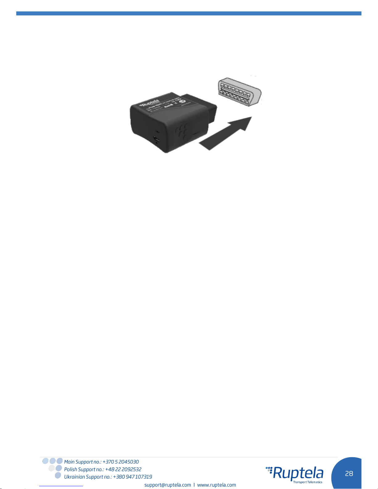
Locate OBD2 socket in your vehicle. Insert FM-Plug4 / FM-Plug4+ device into OBD2 socket as showed
in the picture below. There is only one way to plug the device, be careful not to damage the pins.
 Loading...