

Page 1
OWNER’S OPERATING MANUAL
Virtual High Definition Processor With Aspect Ratio Control
VHD-4404 ULTRA
IRTUAL
TM
V
HIGH DEFINITION
Page 2

Page 3
OWNER’S OPERATING MANUAL
VHD-4404 ULTRA
Virtual High Definition Processor With Aspect Ratio Control
IRTUAL
TM
V
HIGH DEFINITION
Page 4

The software installed in the VHD-4404 ULTRA is protected by copyright
laws and International copyright treaties, as well as other intellectual
property laws and treaties.
IMPORTANT - READ CAREFULLY: This Runco License Agreement is a
legal agreement between you (either an individual or a single entity) and
Runco International for the Runco software product installed within the
VHD-4404 ULTRA. By using the VHD-4404 ULTRA, you agree to be
bound by the terms of this License Agreement. If you do not agree to the
terms of this License Agreement, do not use the VHD-4404 ULTRA; you
may, however, return it to your place of purchase.
© 2001, Runco International. All rights reserved.
2
Page 5

CONTENTS
3
Warnings and Safety Precautions. . . . . . . . . . . 4
Introduction . . . . . . . . . . . . . . . . . . . . . . . . . . . . 6
General Description . . . . . . . . . . . . . . . . . . . . . 6
Features and Benefits . . . . . . . . . . . . . . . . . . . 6
Front and Rear Panel Description. . . . . . . . . . . 7
Front Panel . . . . . . . . . . . . . . . . . . . . . . . . . . . 7
Rear Panel . . . . . . . . . . . . . . . . . . . . . . . . . . . 8
Remote Control Description . . . . . . . . . . . . . . 10
Quick Set-up Guide . . . . . . . . . . . . . . . . . . . . . 11
Connection Examples . . . . . . . . . . . . . . . . . . 11
Getting Started . . . . . . . . . . . . . . . . . . . . . . . 12
Overall Function Description . . . . . . . . . . . . . 13
Compatibility . . . . . . . . . . . . . . . . . . . . . . . . . 13
Menu Description and Navigation . . . . . . . . . . 14
Main Menu . . . . . . . . . . . . . . . . . . . . . . . . . . 14
Picture Quality Adjustments . . . . . . . . . . . . . . 15
Installation Menu . . . . . . . . . . . . . . . . . . . . . . 18
Screen Type . . . . . . . . . . . . . . . . . . . . . . . . . 19
Scan Rate . . . . . . . . . . . . . . . . . . . . . . . . . . . 19
Selecting a Scan Rate . . . . . . . . . . . . . . . . . . 20
Fixed Pixel Displays. . . . . . . . . . . . . . . . . . . . 21
CRT Projectors . . . . . . . . . . . . . . . . . . . . . . . 21
Output Format (Sync) . . . . . . . . . . . . . . . . . . 23
Side Bar Level . . . . . . . . . . . . . . . . . . . . . . . . 24
Blanking . . . . . . . . . . . . . . . . . . . . . . . . . . . . 26
System Reset . . . . . . . . . . . . . . . . . . . . . . . . 26
Aspect Ratios. . . . . . . . . . . . . . . . . . . . . . . . . . 27
Dimensions . . . . . . . . . . . . . . . . . . . . . . . . . . . 29
RS-232 Communications . . . . . . . . . . . . . . . . . 30
Specifications . . . . . . . . . . . . . . . . . . . . . . . . . 33
Supplied Accessories. . . . . . . . . . . . . . . . . . . 33
Page 6
4
CAUTION:
To turn off main power, be sure to remove the plug from power outlet. The power
outlet socket should be installed as near to the equipment as possible, and should
be easily accessible.
REMARQUE:
Pour mettre l’appareil hors circut, s’assurer de retirer la fiche de la prise d’alimentation. La prise d’alimentation doit être installé aussi proche que possible de l’appareil
et doit être facile d’ accès.
TO PREVENT FIRE OR SHOCK HAZARDS, DO NOT EXPOSE THIS UNIT TO
RAIN OR MOISTURE. ALSO DO NOT USE THIS UNIT’S POLARIZED PLUG WITH
AN EXTENSION CORD RECEPTACLE OR OTHER OUTLETS, UNLESS THE
PRONGS CAN BE FULLY INSERTED. REFRAIN FROM OPENING THE CABINET
AS THERE ARE HIGH-VOLTAGE COMPONENTS INSIDE. REFER SERVICING TO
QUALIFIED SERVICE PERSONNEL.
POUR EVITER UN FEU OU UN RISQUE D’ELECTROCUTION NE PAS EXPOSER CET ENSEMBLE A LA PLUIE OU A L’HUMIDITE; DE MEME, NE PAS
BRANCHER LA PRISE POLAIRE AVEC UNE RALLONGE A MOINS QUE LES
DENTS DE LA PREMIERE NE S’Y INSERENT PLEINEMENT.
EVITER D’OUVRIR LE COFFRET CAR IL Y A, A L’INTERIEUR, DES COMPOSANTS SOUMIS A UNE HAUTE-TENSION; POUR LES REPARATIONS,
S’ADRESSER A UN PERSONNEL QUALIFIE.
WARNING
AVERTISSEMENT
Warnings and Safety Precautions
Page 7

5
This equipment has been tested and found to comply with the limits for a Class
B digital device, pursuant to Part 15 of the FCC Rules. These limits are
designed to provide reasonable protection against harmful interference when
the equipment is operated in a commercial environment. This equipment generates, uses, and can radiate radio frequency energy and, if not installed and
used in accordance with the installation manual, may cause harmful interference to radio communications. Operation of this equipment in a residential area
is likely to cause harmful interference, in which case, the user will be required to
correct the interference at his own expense.
DOC compliance Notice
This Class B digital apparatus meets all requirements of the Canadian
Interference-Causing Equipment Regulations.
DOC avis de conformation
Cet appareil numérique de la classe B respecte toutes les exigences du Réglement
sur le Matériel D’interférence du Canada.
WARNING
:
Please read and follow the safety precautions listed below to ensure the equipment
is free from damage, and to ensure that no injury will occur as a result of improper
use.
• Do not insert any object, especially metal or liquids, into the VHD-4404 ULTRA.
• Do not place any objects containing water or any other liquid on top of the
VHD-4404 ULTRA
• Do not place the unit in direct sunlight, near heaters or in extremely dusty or
humid locations
• Do not install this unit outdoors or otherwise exposed to the elements
• Do not place heavy objects on top of the unit
• If the power cord is damaged or frayed in any way, electrical shock and/or fire
may result. Please do not place objects on the power cord, and keep the cord
away from heat-emitting devices. Should the power cord become damaged in
any way, please contact your Runco dealer for a replacement cord.
• Do not remove the cover of the unit for any reason. If any problems arise with
the unit, please contact a Runco dealer or Runco International for service.
Removing the cover will void the warranty.
Safety Tips
Page 8

Welcome to the high-end world of Runco video processing! Your new VHD-4404 ULTRA has been
designed to be flexible enough to be compatible with virtually and type of display device, from different types of CRT projectors to various types of fixed pixel displays. In addition, it will provide
aspect ratio control for those displays that would otherwise not have that capability, whether on a
standard 4:3 screen or a 16:9 (wide) screen.
In general, this processor will greatly improve the video quality and efficiency of the display device it
will be used with. For CRT projectors, the scan rate output of the processor can be set so as to
maximize the resolution AND light output of the projector it is to be used with. For example, projectors with smaller CRTs (i.e. 7") might be used with a scan rate of 540p or 600p; projectors with larger CRTs (i.e. 8" or 9") might use 840p, 960p or even 1080p. And for fixed-pixel displays, the various output resolutions will accommodate many different displays, including DLP™, LCD, D-ILA and
even Plasma monitors. The most efficient way to process video for a fixed-pixel display is to feed
the display with a resolution matched pixel-for-pixel to the display's native resolution.
Finally, many displays do not include any type of aspect ratio control, or have aspect ratio control
limited to 4:3 screens. The VHD-4404 ULTRA can provide three geometrically correct aspect ratios
whether the display is on a 4:3 screen OR a 16:9 screen. In a nutshell, your VHD-4404 ULTRA will
expand the use of any compatible display device while providing top-notch video
processing no other processor can match.
The VHD-4404 ULTRA has many great features and benefits that make it a flexible, high-quality
processor. Its many benefits include:
• An adaptive 2-dimensional comb filter that greatly reduces artifacts when using a composite video
signal as an input.
• A Luma edge enhancement circuit makes the edges of objects appear sharper without the
ringing and noise increase associated with traditional sharpness circuits
• A Chroma edge enhancement circuit is included to compensate for lower chroma resolution found
in composite and S-video.
• Inverse Telecine (3:2 pulldown) detection and processing allows the scaler to almost completely
eliminate interlace artifacts associated with other scalers
• The controller can correctly scale anamorphic, letterbox and 4:3 formats to fit on a wide aspect-ratio
screen, and scale anamorphic formats on a 4:3 screen
• A pass-through connector is supplied for routing HDTV or computer graphics directly to the
display.
• An RS-232 input is provided for easy integration into the automated home theater environment
• A TBC (Time Base Corrector) circuit is provided for unstable sources such as VCR’s.
• 12V outputs are provided for drop screens and screen masking.
• A simple 7-button remote controls all aspects of operation. One button source selection and aspect
ratio control is also provided via the remote control.
6
INTRODUCTION
General Description
Features and Benefits
Page 9
7
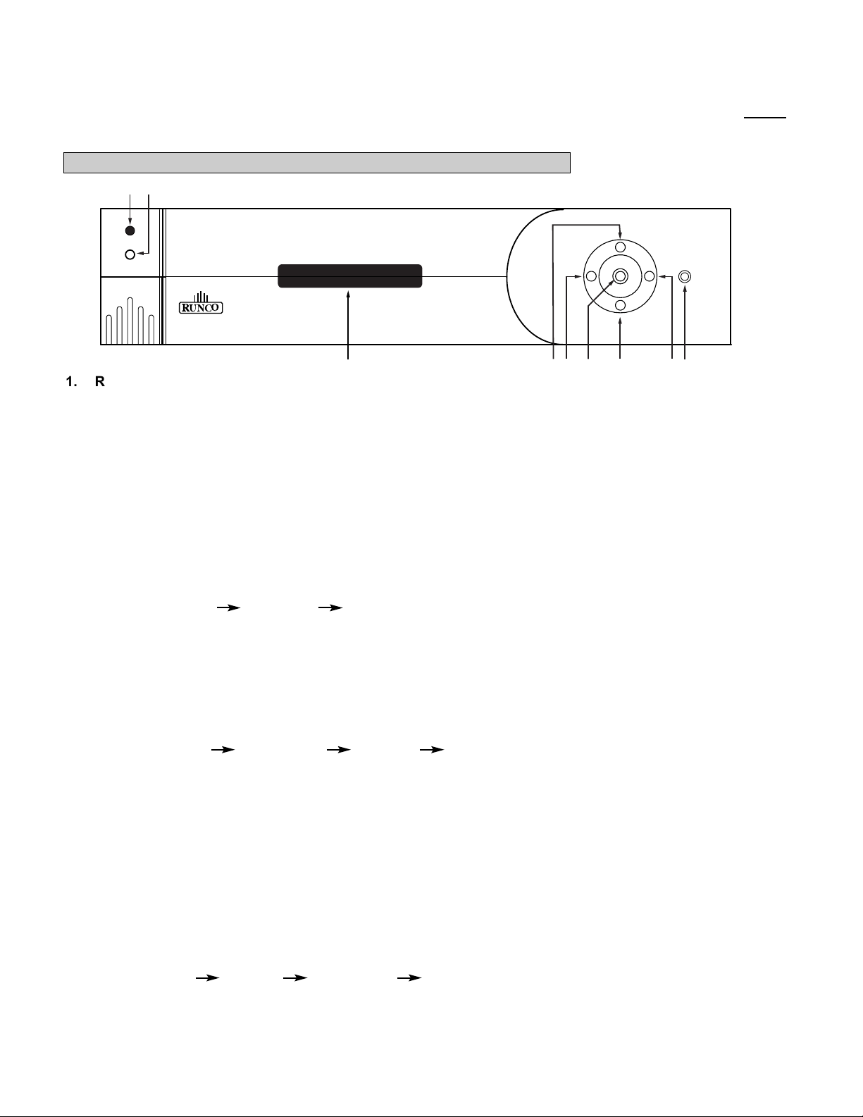
FRONT AND REAR PANEL DESCRIPTIONS
Front Panel
1. IR RECEIVER
Receives the IR commands from the remote control.
2. POWER BUTTON
Toggles the power on and off. For a discreet on or off command, you can use the direct access buttons.
NOTE: When the main AC power switch is first turned ON, the processor will go through an initiation cycle for
approximately 15 seconds. The processor cannot be turned on or operated until the initialization is complete
3. LED DISPLAY
Indicates the model#, current source, scan rate or resolution and aspect ratio.
4. UP BUTTON
When no menus are present on-screen, the UP button will toggle you through aspect ratios in the following order:
Standard (4:3) Letterbox Anamorphic
When the menu is on-screen, the UP button will move the cursor up within the menu.
When an adjustment item has been selected (i.e. brightness), the UP button will increase the value of that
function.
5. LEFT BUTTON
When no menu is present on-screen, the LEFT button will toggle you through the four different sources, in the
order of:
Pass-through Component S-Video Composite
6. ENTER BUTTON
When an item is highlighted on the On-Screen Display, the ENTER button will select the item.
7. DOWN BUTTON
When no menu is present on-screen, this button will toggle you through the different aspect ratios.
When the menu is on-screen, the down button will move the cursor down within a menu. When an adjustment
function has been selected (i.e. brightness), the DOWN button will decrease the value of that function.
8. RIGHT BUTTON
When no menus are present on-screen, the RIGHT button will toggle you through the four different sources, in
the order of:
Composite S-Video Component Pass-through
9. MENU BUTTON
Pressing the MENU button will bring up the main menu. If no action is taken within approximately 10 seconds,
the menu will time-out (disappear). Also, if you are in an adjustment mode or function, pressing MENU will bring
the menu back one level.
2
1
n
e
u
M
4404 ULTRA
O
C
UN
R
MULTIFILM
7
345
6 9
8
Page 10
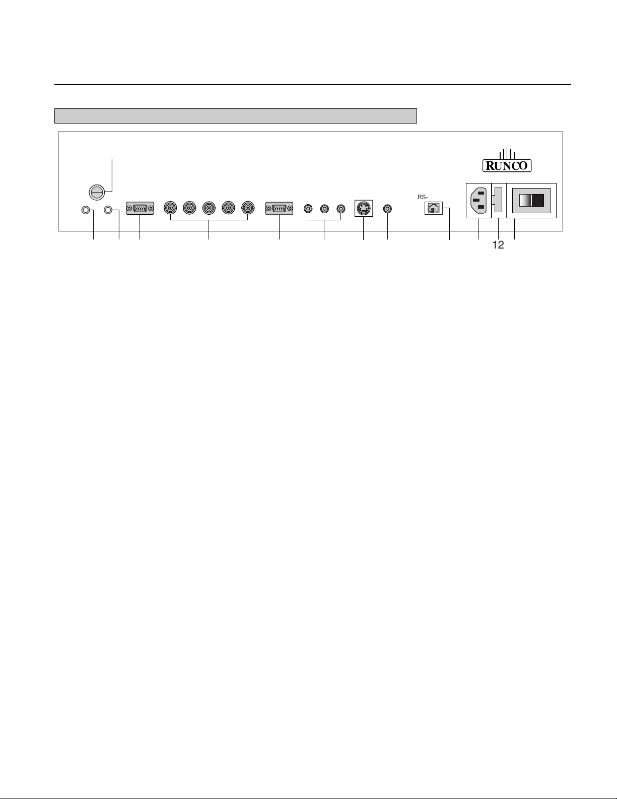
8
1. 12v Fuse
This fuse protects the 12v outputs from the MASK and SCREEN jacks.
(Screen Fuse: 5mm x 25mm, AGC, 0.5A 250V Fast Acting, 250V, Fast Blow)
2. Mask
This is a 12V output that is used to trigger masking on screens that have that capability.
(For use on motorized screens only).
3. Screen
This is a 12V output that is used to trigger the screen to drop.
(For use on motorized screens only).
4. RS-232 In
This is for systems using serial (RS-232) to control the VHD-4404 ULTRA.
5. RGB OUTPUT
This is the main output of the VHD-4404 ULTRA. The RGB Signal goes directly to the projector; If
component is used through the pass-through, then only the R (Pr), G(Y) and B(Pb) jacks will be active.
Individually, the jacks are: V=vertical sync, H=horizontal sync, B=Blue, G=Green, R=Red.
NOTE: If setting the output for ‘sync on green’ or ‘component’ (see Installation Menu section); disconnect
the sync cables (H & V) from the processor. If using composite sync, the sync output will be on the ‘H’
connector.
6. Pass-through
Anything input to this port will by-pass the processing of the VHD-4404 ULTRA and be sent straight to the
display. This is useful for computer graphics and HDTV signals which do not require processing.
7. Component Input
This is the input for component video from sources such as DVD players.
Note:
The component output from a DTV decoder or a progressive-scan DVD cannot be used with this port; it
must be input to the Pass-through port.
8. S-Video Input
This is the input for S-video from sources such as Satellite receivers, S-VHS VCR’s and DVD players.
9. Composite Video Input
This is the input for Composite video from sources such as Laser disc players, VCRs and other
miscellaneous video sources.
Rear Panel
1
12v Fuse
RS-232 IN
Mask Screen
VHBGR
Pass-through
O
C
UN
R
S-VIDEO
Y
Pb
Pr
COMPOSITE
RS-232 OUT
2 3 4 5 6 7 8 9 11 13
10
12
Page 11

10. RS-232 OUT
Reserved for future use.
11. Power Input
Plug in main power here.
12. 115 VAC Fuse
This is the main AC input fuse.
(Main Fuse: 5mm x 20 mm, 500mA, 250v, Slow Blow)
13. Main Power Switch
Disconnects or applies main power to the processor.
9
Page 12
10
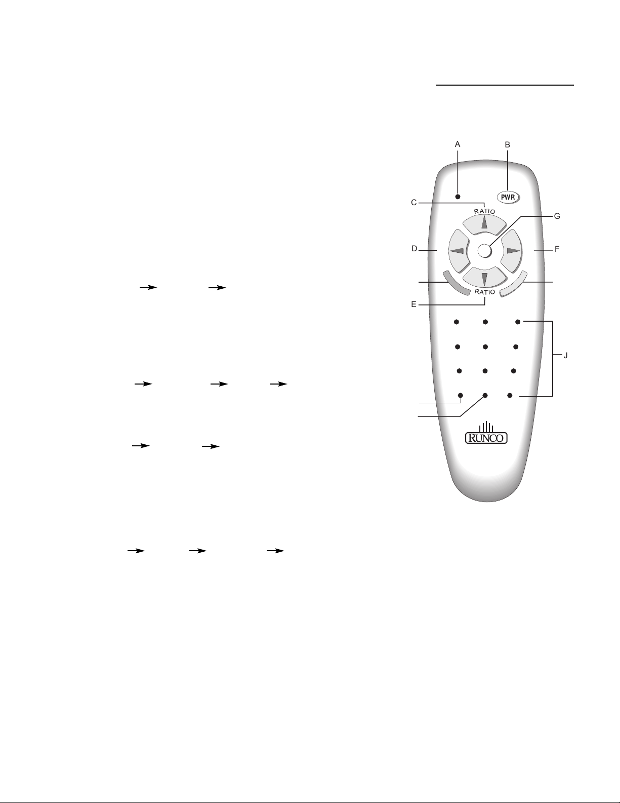
A. IR OUTPUT INDICATOR
Illuminates when a button is pressed, indicating that an IR signal is being
transmitted.
B. POWER BUTTON
Toggles the power on and off. For a discreet on or off command, you can
use the direct access buttons (see 'J'). Note: When the main AC power
switch is first turned ON, the processor will go through an initiation cycle
for approximately 15 seconds. The processor cannot be turned on or
operated until the initialization is complete.
C. UP BUTTON
When no menus are present on-screen, the UP button will toggle you
through aspect ratios in the following order:
Standard (4:3) Letterbox Anamorphic
When the menu is on-screen, the UP button will move the cursor up
within the menu. When an adjustment item has been selected (i.e.
brightness), the UP button will increase the value of that function.
D. LEFT BUTTON
When no menus are present on-screen, the LEFT button will toggle you
through the four different sources in the following order:
Pass-through Component S-Video Composite
E. DOWN BUTTON
When no menus are present on-screen, the DOWN button will toggle you
through aspect ratios in the following order:
Anamorphic Letterbox Standard (4:3)
When the menu is on-screen, the DOWN button will move the cursor
down within the menu. When an adjustment item has been selected (i.e.
brightness), the DOWN button will decrease the value of that function.
F. RIGHT BUTTON
When no menus are present on-screen, the RIGHT button will toggle you
through the four different sources in the following order:
Composite S-Video Component Pass-through
G. MENU BUTTON
Pressing the MENU button will bring up the main menu. If no action is
taken within approximately 10 seconds, the menu will time-out (disappear). Also, if you are in an adjustment mode or function, pressing MENU
will bring the menu back one level.
H. ENTER BUTTON
When an item is highlighted on a menu, pressing ENTER will select that
item.
I. PROGRAM BUTTON
If the remote control loses its 'memory' as a result of weak or dead batteries, it must be re-programmed for the VHD-4404 ULTRA's code set.
To reprogram the remote, press the PROGRAM button followed by 0,1,3.
Note: Pressing Enter after typing in the code is not necessary.
J. DIRECT ACCESS BUTTONS
These buttons will allow you to directly
access an aspect ratio, source, or turn the
unit on or off without having to go through
any menus. These buttons are:
1: Selects COMPOSITE video
2: Selects S-video
3: Selects COMPONENT video
4: Not used
5: Selects PASS-THROUGH
6: Enables or Disables the Installation
Menu (see page 18)
7: Selects the ANAMORPHIC aspect ratio
8: Selects the STANDARD (4:3) aspect
ratio
9: Selects the LETTERBOX aspect ratio
0: Turns the processor ON.
OFF: Also known as the button left of '0',
this turns the processor OFF.
REMOTE CONTROL DESCRIPTION
C
D
I
E
A
I
N
P
U
T
12 3
B
PWR
M
G
I
N
P
U
T
F
H
45 6
78 9
OFF
ON
R
UNCO
0
J
Page 13

While there are many different ways to connect your source equipment to your
VHD-4404 ULTRA, the examples shown above are the most common.
• COMPOSITE VIDEO INPUT:
Composite video is the most common type of signal used, but is also the lowest in
picture quality. Many sources have outputs that are limited to composite video, such
as some VCR’s and camcorders; others such as Laser Disc players actually produce slightly better results when using composite video.
• S-VIDEO INPUT
S-video is the second-best type of signal that can be used, but is MUCH better than
composite video. Using such sources as Satellite receivers, high-quality VCRs and
DVD players (with no component output) will produce a MUCH cleaner and sharper
signal.
• COMPONENT INPUT
Component video is the best type of signal that can be used. The most common
sources that use component outputs are DVD players, and it is highly recommended that component be used when possible. Component video goes one step
beyond S-video in picture quality; chroma (color) information is more resolved and
the overall picture appears more well-defined.
• PASS-THROUGH
This input is used to ‘pass-through’ any high-definition or computer signals that do
not require processing. The signal by-passes the VHD-4404 ULTRA’s processing
and is sent directly to the display. The pass-through may be used for COMPONENT
outputs from a DTV decoder, a progressive-scan DVD player or RGB outputs from
a computer or other high-resolution sources.
11
QUICK SET-UP GUIDE
Connection Examples
12v Fuse
RS-232 IN
Mask Screen
VHBG R
O
C
U
N
R
Pass-through
Y
DVD Player
Display Device
Automation
System
Computer or
DTV decoder
Sattelite
receiver or
SVHS player
S-VIDEO
Pb
Pr
COMPOSITE
C
U
N
R
RS-232 OUT
Reserved for future use
VCR, Laser
disc player,
camcorders
O
Page 14

12
Now that your VHD-4404 ULTRA has been installed, it's time to get it configured for
use in your system. Please follow the procedures and recommendations below:
1. First, connect all sources (DVD, VCR, Satellite receiver, etc.) to the VHD-4404 ULTRA, if this has not
already been done. Also, ensure all sources are ON and functioning, if possible.
2. Connect the RGB (or component) output of the VHD-4404 ULTRA to the display device it is to be used
with. NOTE: It may be necessary to set the 'output format' and 'scan rate' in the Installation menu to
match the input type and scan rate of the display device it is to be used with (see page 19).
3. With everything properly connected, turn the VHD-4404 ULTRA on, followed by the display device itself.
4. If the output scan rate and output format have not been optimized for the display device the processor will
be used with, set them now (see page 19 for recommendations).
5. Next, set the 'screen type' in the installation menu, either 16:9 screen (for installations using widescreens
or other display devices with a 16:9 aspect ratio (i.e. a plasma display)) or 4:3 screen for those displays
using a 4:3 screen only.
Once the initial settings have been completed, the 'front panel settings' (color, tint,
sharpness, etc.) can be adjusted for each aspect ratio. The calibration procedures for
these adjustments are outlined in 'picture quality adjustments', page 15.
Getting Started
Page 15

13
Overall Functional Description
The VHD-4404 ULTRA has many useful purposes. It has many different scan rate outputs
that can match most types of displays, including CRT projectors and fixed-pixel displays. Also,
the sync polarity and output type (RGB, Component, Sync on green, etc.) can be changed to
meet the requirements of the display device, ensuring that the VHD-4404 ULTRA will be fully
compatible in all respects to just about every type of display.
In addition to being compatible with most displays, it also includes aspect-ratio control. This is
extremely beneficial for those displays that do not have any type of aspect ratio control, as all
movies can now be viewed in their native format instead of having to settle for 4:3.
So, how does the VHD-4404 ULTRA work, anyways? In a nutshell, the VHD-4404 ULTRA
is an advanced processor known as a SCALER. A scaler takes the interlaced NTSC signal
(such as that from a standard DVD player or VCR, for example), de-interlaces it, and then
scales it to one of many selectable resolutions. It is the advanced Runco scaling algorithms
that gives the VHD-4404 ULTRA the ability to change not only scan rates and resolutions, but
aspect ratios as well.
As mentioned, the VHD-4404 ULTRA is compatible with many types of display devices. To
ensure a display device is capable of working with the VHD-4404 ULTRA, it must have the
following specifications:
• Capable of a horizontal scan rate of at least 31.5 KHz
• Capable of a resolution of at least 854 x 480
• Can accept RGB (separate or composite syncs, or sync on green), or component signals
In addition, the processor is designed to work properly on widescreens with an aspect ratio of
either 1.78:1 (16:9) or 1.85:1, or any 4:3 screen. The processor is not designed to provide
aspect ratio control for 2.35:1 screens.
For input signals, the VHD-4404 ULTRA can accept NTSC or PAL signals from most typical
sources. This includes interlaced signals from standard DVD players, Satellite receivers,
VCRs, Laser Disc players, camcorders and other similar equipment. For higher-resolution signals such as a computer, high-definition decoder or progressive DVD players, these signals
MUST be connected to the Pass-through port. The VHD-4404 ULTRA will not accept
progressive signals on its Component input port (i.e. progressive DVD players).
Please ensure that your display device is compatible with any high-resolution signal you input
to the pass-through port. NOTE: The VHD-4404 ULTRA will not process any signal on its
pass-through port; it will simply loop the signal directly to its output. Also, the pass-through
port will not convert component signals to RGB signals; component signals input to the passthrough port will be output as component signals.
Compatibility
Page 16

14
When the MENU button is pressed on either the remote control or the front panel, the main menu
will appear on-screen. An example of the main menu is shown above.
The active source is indicated by an arrow to the left of the source; note that in the example
above, Composite is the current source.
To select a source via the main menu, press either the up or down buttons on the remote or
front panel and highlight the desired source, and press ENTER. Otherwise, you may select a
source by pressing either the left or right arrow buttons (on the remote or front panel) when no
menus are on-screen, or by pressing one of the direct access buttons on the remote control
(recommended; see page 10).
If pass-through is selected, note that no on-screen menus will be displayed since the signal is
simply being 'looped' directly to the RGB output. When pass-through is the selected source,
pressing MENU will automatically select S-video as the source. If you wish to choose another
source, Runco recommends using the direct access buttons to select the desired source as
opposed to pressing MENU.
Aspect Ratio provides selection of one of three aspect ratios: Anamorphic, Letterbox or standard
4:3. To select an aspect ratio via the main menu, press either the up and down buttons on the
remote or front panel, highlight ASPECT RATIO and press ENTER. The aspect ratio menu will
then appear with the three choices; highlight the desired aspect ratio with the up or down buttons
and press ENTER. Otherwise, you may select an aspect ratio by pressing either the up or down
arrow buttons (on the remote or front panel) when no menus are on-screen (see page 10), or by
pressing one of the direct access buttons on the remote control (recommended; see page 10).
Installation is where the scan rate and sync types can be adjusted, as well as screen types,
'side bar' levels, image shift and blanking controls. A full description of this menu is on page 18.
NOTE: If INSTALLATION does not appear on the main menu, see page 18 for an explanation on
how to access the Installation menu.
MENU DESCRIPTION AND NAVIGATION
Main Menu
MAIN MENU
COMPOSITE
>
S-VIDEO
COMPONENT
PASS THROUGH
ASPECT RATIO
INSTALLATION
Source selection and
picture quality adjustments
Aspect ratio selection
See "installation" section
Page 17

Picture quality adjustments (also known as "Front Panel Controls") are the controls that change different
parameters of the image such as the amount of color, black level, etc. While these adjustments can be set to
suit the needs of the user, there is a way to set these properly. This section will describe what each function
does and how to adjust them properly.
To access the picture quality adjustments, press MENU, highlight the active source (indicated by the arrow)
and press ENTER. The picture quality sub-menu will then appear (see above).
To make an adjustment to a particular function, highlight the function with the up or down arrow buttons and
press ENTER. Once the function is on-screen (i.e. brightness), pressing the UP arrow button on the remote or
front panel will increase the value of that function; pressing the DOWN arrow on the remote or front panel will
decrease the value of that function.
While each of the picture quality adjustments can be set to suit the needs of the user, there is a 'proper' way
to set the adjustments. For setting TINT and COLOR, please refer to the color bar test pattern below.
NOTE: For many display devices, a BLUE FILTER must be used so only the blue color bars can be seen; if
no blue color filter is available, see if the display device has the ability to mute (turn off) the red and green
colors via its menu structure (most CRT projectors have this feature). Blue filters are provided with the Video
Essentials or AVIA test DVDs, or can be purchased from the Imaging Science Foundation
(www.imagingscience.com).
15
Picture Quality Adjustments
MAIN MENU
COMPOSITE
>
S-VIDEO
COMPONENT
PASS THROUGH
ASPECT RATIO
INSTALLATION
TINT
COLOR
BRIGHTNESS
CONTRAST
SHARPNESS
LUMA ENHANCE
CHROMA ENHANCE
Tall color bars
white
cyan
yellow
green
red
blue
magenta
Short color bars
Tint
Color
Page 18

16
TINT (also known as 'hue') is essentially the ratio of red to green in the color portion of the image. If TINT is
decreased, the image will appear redder, and increasing it will cause the image to appear greener. To set
TINT properly, look at the color bar pattern through a blue filter (or mute the red and green outputs). Adjust
TINT until the middle two tall color bars match the middle short color bars (see color bar drawing).
COLOR (also known as 'saturation') increases or decreases the amount of color in the image. To set
COLOR properly, look at the color bar pattern through a blue filter (or mute the red and green outputs).
Adjust COLOR until the outer two tall color bars match the outer short color bars (see color bar drawing).
For setting CONTRAST and BRIGHTNESS, please refer to the PLUGE pattern below:
CONTRAST adjusts the white level of the image. To adjust this properly for CRT projectors, adjust CON-
TRAST until there is no blooming (or distortion) in the brightest bar in the PLUGE pattern (see above).
For Fixed-pixel displays, adjust contrast until there is a distinct definition between the two brightest bars.
NOTE: For best results, Runco recommends that CONTRAST be set to '0' or very close to it.
BRIGHTNESS adjusts the black level of the image. To adjust this properly, adjust BRIGHTNESS until the
'below black' bar JUST disappears, but the 'above black' bar is still barely visible.
NOTE: Some DVD players cannot pass the 'blacker than black' bar (they won't pass PLUGE), and that bar
will never be visible. In a case like this, adjust the 'above black' bar until it is slightly brighter than the background that surrounds it.
Set contrast
untill there is
no 'blooming'
in this bar.
Below black
Above black
Page 19

SHARPNESS adjusts the amount of high-frequency detail in the image. This can be adjusted to the prefer-
ence of the user. Keep in mind that when SHARPNESS is decreased, fine details in the image will become
'soft'; when it is increased, fine details will become sharper but will also make the picture appear 'noisy' if
adjusted too high.
LUMA ENHANCE acts as an edge enhancement, especially around black to white transitions in the image.
Essentially, this has the same characteristics as sharpness but affects the edges of objects far more that the
rest of the image.
FREQUENCIES HIGH/LOW affect the overall range of the LUMA ENHANCE feature. For example, if using a
lower-quality video source such as a VCR, the FREQUENCIES should be set to LOW. For a good quality
source such as a DVD player, set FREQUENCIES to HIGH. To set FREQUENCIES, press ENTER while
LUMA ENHANCE is on-screen.
CHROMA ENHANCE acts as an edge enhancement, especially around color transitions in the image.
Essentially, this has the same characteristics as sharpness but affects the edges of objects far more that the
rest of the image.
FREQUENCIES HIGH/LOW affect the overall range of the CHROMA ENHANCE feature. For example, if using
a lower-quality video source such as a VCR, the FREQUENCIES should be set to LOW. For a good quality
source such as a DVD player, set FREQUENCIES to HIGH. To set FREQUENCIES, press ENTER while
CHROMA ENHANCE is on-screen.
17
Page 20

The Installation menu is where you can adjust the scan rate and sync type, as well as set the type of screen
(4:3 or 16:9), shift the image or set blanking, and even set the level of the 'sidebars'.
When the VHD-4404 ULTRA is turned on for the first time, the INSTALLATION item will not appear in the
main menu. To enable the INSTALLATION menu, there are two options:
· With the processor ON and no menus on-screen, simultaneously press the ENTER, UP and LEFT buttons
(you don't need to hold them down). Release the three buttons and press MENU, ensure INSTALLATION is
now on the bottom of the main menu.
· With the remote control, press button 6 (with no menus on-screen).
After pressing '6', press MENU and ensure INSTALLATION is now on the bottom of the main menu.
After INSTALLATION has been accessed, press MENU, highlight INSTALLATION and press ENTER.
This will bring up the INSTALLATION MENU, shown below:
Installation Menu
INSTALLATION
4:3 SCREEN
16:9 SCREEN
SCAN RATE
OUTPUT FORMAT
SIDE BAR LEVEL
IMAGE SHIFT
BLANKING
18
Page 21

When you are installing the processor for the first time, the first order of business is to define what type of
screen will be used with this system. If a 1.78:1 (16:9) or 1.85:1 screen is used, highlight 16:9 SCREEN and
press ENTER. If a standard 4:3 screen is installed, highlight 4:3 SCREEN and press enter.
The purpose of defining the screen type is to tell the processor how to create aspect ratios (see page 27 for a
definition of aspect ratios). For example, on a 16:9 screen, the letterbox and anamorphic aspect ratios will use
the entire 16:9 screen, and the 4:3 aspect ratio will be displayed in the center of the 16:9 screen (you'd have
'black bars' on the left and right sides of the image).
On the other hand, on a 4:3 screen, the 4:3 aspect ratio would fill the screen, but the letterbox and
anamorphic aspect ratios would be displayed in the center of the screen vertically (there would be 'black bars'
on the top on bottom of the image).
Important note on aspect ratios for 4:3 screens: If 4:3 SCREEN is selected, the only way the processor
will provide all three aspect ratios is if one of the FIXED PIXEL scan rates are selected (i.e. 1024 x 768).
The processor will NOT provide three aspect ratios on a 4:3 screen if a CRT scan rate is selected (i.e. 600p).
The reason for this is that CRT projectors will provide the best resolution if two separate memories are
created by the projector itself, one for anamorphic, one for full 4:3. This way, the CRT projector can provide
the maximum number of lines of resolution on either aspect ratio since it is simply compressing a 4:3 image
to an anamorphic image. Therefore, Runco recommends that the CRT projector create the aspect ratios on
4:3 screens (if possible) for best results.
For fixed pixel displays, the number of pixels cannot be changed nor do many of the displays provide the
ability to create aspect ratios. Therefore, the VHD-4404 ULTRA will provide three full aspect ratios for fixed
pixel displays (WHEN a fixed-pixel scan rate is selected) for use on 4:3 screens.
In any event, if 16:9 SCREEN is selected, the VHD-4404 ULTRA will provide three aspect ratios regardless
of the selection of the scan rate type or display device used.
SCAN RATE is how many lines of resolution can be output in a single image. For example, 540p means that
there are 540 visible lines of resolution, and 'p' means the signal is PROGRESSIVE. A Progressive output is
where ALL lines of resolution will be displayed during each frame as opposed to an INTERLACED signal,
which only displays half the lines of the frame during one field and the other half the next. Progressive outputs
are far better than Interlaced outputs as all lines of resolution are always displayed, and fixed-pixel displays
produce far better results when using a progressive signal.
The fixed-pixel outputs are also progressive, but are referred to in PIXELS (Picture Elements) as opposed to
the actual number of lines of resolution. This is because fixed-pixel displays are referred to in their native
resolution in pixels, i.e. 1024 x 768 (meaning 1024 vertical rows of pixels and 768 horizontal rows of pixels).
Selecting a scan rate for your display device is an extremely important task. The first thing that should be
done is to determine what scan rate will provide the best results for your display. The following are some
guidelines that will assist you in determining the best possible scan rate for your type of projector.
19
Screen Type
Scan Rate
Page 22

To select a scan rate, first determine which type of display will be used with the VHD-4404 ULTRA
(see 'Fixed pixel displays' or 'CRT displays' below). If the display is a FIXED PIXEL display, you'll want to
use one of the FIXED PIXEL scan rates. If using a CRT projector, you'll want to use one of the CRT scan
rates.
To select a scan rate, follow this procedure:
· Press MENU and ensure 'INSTALLATION' is on the bottom of the menu. If it's not, enable the
INSTALLATION menu using the procedures on page 18.
· Using the up or down arrow buttons, highlight INSTALLATION and press ENTER.
· Once the INSTALLATION menu is on-screen, use the up or down arrow buttons to highlight SCAN
RATE and press ENTER.
· Note that at the top of the SCAN RATE menu that it will say either "SCAN RATE-CRT" or "SCAN RATEFIXED PIXEL"; if it indicates the wrong mode for your system (i.e. you have a CRT projector but the
menu says "FIXED PIXEL"), simply highlight the word "MORE…" on the bottom of the menu and press
ENTER. This will toggle you to the appropriate scan rate type for your display.
· Next, highlight the desired SCAN RATE and press ENTER. The VHD-4404 ULTRA will immediately go
to that scan rate. To confirm your scan rate selection, you must press MENU within ten seconds or the
processor will revert to the scan rate it was at before you made the selection. Runco recommends that
you ensure your display device produces an image before confirming the scan rate. If it does not, allow
the processor to revert to its previous scan rate and consult the owner's manual of your display to see
what it's scan rate or resolution capabilities are.
SCAN RATE menus:
Note that the arrow indicates the currently selected scan rate (600p, in this example).
20
SCAN RATE-CRT
540p
>600p
720p
768p
840p
960p
1080p
MORE…
SCAN RATE-FIXED PIXEL
800 x 600
854 x 480
1024 x 768
1024 x 768 (A)
1280 x 768
1366 x 768
1280 x 1024
1366 x 1024
MORE…
Selecting A Scan Rate
Page 23

A fixed pixel display can be one of several types of displays, including Plasma (flat panel) displays, DLP™
projectors, LCD projectors and D-ILA projectors. Selecting a scan rate for these types of displays is actually
quite easy since the display has a fixed resolution, commonly known as the display's native resolution.
To determine which scan rate output to use, first determine your display's native resolution. For example, if
you have a DLP™ or an LCD projector with a native resolution of 1024 x 768, set the SCAN RATE for
1024 x 768. If the display has a native resolution of 1024 x 768 and is using an anamorphic lens, select
1024 x 768 (A).
Runco recommends that for fixed-pixel displays the output scan rate ALWAYS be set to match the native
resolution of the display for best results. Selecting a resolution output higher or lower than that of the native
resolution of the display will cause the display to scale the image, resulting is decreased resolution and
performance.
If you have a fixed-pixel display and its native resolution does not match any of the resolution outputs of the
VHD-4404 ULTRA, try different resolutions to see which one gives you the best picture quality.
Determining the best scan rate output for your CRT display is not quite as straightforward as choosing a
resolution output for a fixed-pixel display, but following these guidelines will help you easily choose the best
scan rate for your CRT display.
There are two factors with CRT projectors that directly affect which scan rate will work best with them- CRT
size and type of electronic focus. It is important to note that while a particular CRT projector can handle a
certain scan rate range, inputting a scan rate at the top end of its range may NOT be the best scan rate for
the projector. In other words, just because a projector with 7" CRTs and electrostatic focus can display a
signal with a scan rate between 15 and 65 KHz, using a quadrupler (63 KHz) would produce an extremely
soft and dull picture. Inputting a signal around 38 KHz, however, will produce a bright, sharp image.
Ultimately, the goal with a CRT projector is to display as many scan lines as possible before the lines are so
close together that they actually touch and 'write over' each other. If too many lines are displayed to the point
where they're touching, the image will become very soft and unresolved. If too few lines are displayed, the
image will be sharp but not nearly as bright, as not enough of the phosphor is being used. Therefore, the best
scan rate is that which allows both maximum brightness AND resolution from the projector.
The size of the CRT makes a huge difference in a projector's resolution capability; the larger the CRT, the
more resolution it can handle. Basically, a larger CRT has more physical surface area, so more resolution can
be displayed without it 'running out of room to breathe'. This means, by definition, that a larger CRT demands
a higher scan rate. Smaller CRTs will, of course, need a slower scan rate.
While there are many sizes of CRTs, the most common in use today are 7-inch, 8-inch and 9-inch CRTs.
Some rear-screen projection televisions use even smaller (5-inch) CRTs, and one manufacturer actually
produces a 12-inch CRT, but the 7-inch to 9-inch range is far more common.
21
Fixed Pixel Displays
CRT Projectors
Page 24

The type of electronic focus that the projector uses also affects what scan rate work best with it. There are
two types of electronic focus- Electrostatic and Electromagnetic. Electrostatic is a basic type of focus, where
just turning a 'focus pot' is all the control of electronic focus you have. This work fine, but really only provides
the best results in the center area of the image. The 'beam spot size' of the electrostatically focused projector
is also larger; this means that the electron beam that creates the image in a CRT is larger. As a result, a projector using electrostatic focus will work better with a slower scan rate.
Electromagnetic focus, however, provides a much more accurate focus. This type of focus cannot only sharpen the center of the image, but each side and corner (in many cases) individually as well. The beam spot size
is also smaller with this type of projector, meaning that it can perform better with a faster scan rate.
The following is a general guideline for determining the best scan rate for your type of CRT projector. This is
only meant as a helpful guideline; the best results are ultimately determined by the condition of the projector
and the quality of the projector's calibration. Use this as a 'starting point' for determining the best scan rate for
your projector, and make changes based on the performance of YOUR projector.
Note: For the actual horizontal scan rate of each output (i.e. 540p=33.8 KHz), please refer to the
SPECIFICATIONS page at the end of this manual.
22
CRT size Type of focus Recommended scan rates
7-inch Electrostatic 540p, 600p
7-inch Electromagnetic 600p, 720p, 768p
8-inch Electrostatic 720p, 768p
8-inch Electromagnetic 768p, 840p
9-inch Electrostatic 768p, 840p
9-inch Electromagnetic 960p, 1080p
Page 25

This feature allows you to change the sync polarity or type of output of the VHD-4404 ULTRA. The default
output is negative horizontal sync, negative vertical sync (- Horizontal - Vertical). However, some display
devices work better with some sync polarities and some may not be compatible with others. There is not a 'best
type of sync' to use (unlike the best scan rate), it's just that each display is designed differently and have their
own requirements. Consult the owner's manual to see what type of sync or sync polarity is recommended for
your display device.
OUTPUT FORMAT Menu
Note that the arrow indicates the currently selected sync output
(Negative horizontal, Negative Vertical in this example).
Besides sync polarity options, you may also choose COMPOSITE SYNC, SYNC ON GREEN or COMPONENT.
COMPOSITE SYNC is the combination of horizontal and vertical syncs on one connector, which is output on
the H sync connector on the rear of the processor (see page 8). Many projectors have a 'four-wire' RGB input
(as opposed to the more common five-wire), meaning that they must have composite sync to function.
SYNC ON GREEN is where the horizontal and vertical syncs are actually combined with the green signal.
Some older displays used sync on green as opposed to RGB and separate or composite syncs.
COMPONENT (Y, Pb, Pr) is a bit different from RGB; instead of the video and color information being
combined on the Red, Green and Blue outputs and having the sync on separate cables (H and V), Component
is actually the Luminance (the black and white part of the image) on the 'Y' output (which also includes the sync
information), and the color information on the Pb (blue) and Pr (red) outputs. Many types of displays, especially
rear-screen projection televisions (RPTV's), use Component inputs exclusively and do not have RGB inputs.
23
OUTPUT FORMAT (SYNC)
- Horizontal - Vertical
+ Horizontal - Vertical
- Horizontal + Vertical
+ Horizontal + Vertical
C SYNC
Sync On Green
Component
Output Format (Sync)
Page 26

Some displays, especially phosphor-based displays such as CRT projectors and Plasma (flat panel) displays, can be 'burned' by still-images or otherwise not using the full display or raster. Examples of this
include ATM's, where the bank logo is permanently burned into the display. This is also the reason why
most projector manufacturers strongly recommend against the use of video games with projection televisions, as many video games have still images in them.
Some types of projectors are not susceptible to burns, like DLP™ projectors. Since a DLP™ projector uses
tiny mirrors to create the image, burning the image is not a concern as the reflectivity of the mirrors does not
decay like the phosphor in a CRT or Plasma.
Besides still images, using a 4:3 image on a widescreen display could cause a '4:3 burn' (see below):
The example above shows what would happen on a widescreen display if a small 4:3 image were used
more often than widescreen images. This happens most frequently with CRT projectors or RPTV's, or
Plasma displays.
To minimize this problem, the VHD-4404 ULTRA can provide SIDE BARS, which will put grey bars up on
either side of a small 4:3 image (see 'side bar area' in the drawing above). This illuminates the otherwise
unused portion of the display, minimizing a potential 4:3 burn.
SIDE BAR LEVEL is the amount of illumination in the side bars. The goal is not to make them so bright that
they are much brighter than the 4:3 image itself (which could cause a reverse 4:3 burn), but not too dim
where they cannot be effective. While there is not a recommended level, Runco recommends keeping the
side bar level at a moderate level, approximately the same as the average light used on the 4:3 portion of
the image.
NOTE: SIDE BAR LEVEL is only active on 16:9 screens. For 4:3 screens, side bar level is not active.
24
Side
Bar
Area
Side
Bar
Area
‘4:3 burn’
Widescreen display
Side Bar Level
Page 27

To use side bar level, it will be necessary to 'unblank' the left and right sides of the image.
Please follow this procedure to set side bar level:
· Ensure an active source is displayed on the screen or display.
· Select the standard (4:3) aspect ratio. NOTE: Ensure 16:9 screen is selected in the
INSTALLATION menu.
· Access the INSTALLATION menu, highlight BLANKING and press ENTER.
· Highlight LEFT with the up or down arrow buttons, then press and hold the left arrow
button. You will begin to see the sidebar slowly appear on the left side.
Continue holding down the left arrow button until the left sidebar fills the left side of
the screen.
· When the left side is fully unblanked, perform the same procedure for the right side.
· Once both sides are fully unblanked, you can set the level of the sidebars. Highlight
SIDE BAR LEVEL on the INSTALLATION menu and press ENTER. Use the up arrow
button to increase the illumination of the side bars, or the down arrow to decrease
their illumination. NOTE: It is recommended that an active image be displayed onscreen, and the level of the sidebars be set to match the average amount of illumina
tion on the 4:3 portion of the image.
IMAGE SHIFT moves the entire image up, down, left or right. If the image is slightly off-center on-screen
after installation, using IMAGE SHIFT can center the image on your screen or display.
While using IMAGE SHIFT will not cause any problems with your display, it is possible to use too much
image shift, which could cause the image to shake or disappear. Therefore, Runco recommends that image
shift be done with the display device itself whenever possible.
25
Runco 4404U
Side Bar Level 013
Image Shift
Hstart: 268
Vstart: 131
Image Shift
Page 28

The BLANKING function allows you to 'cut off' part of the image to fit the screen properly, or to eliminate
anomalies on the extreme outsides (usually the top) of the image. This can be done to the top, bottom, left
or right sides individually.
To adjust BLANKING, highlight the desired area you wish to blank (top, bottom, left or right), and use the left
and right arrows to make the adjustment.
Most CRT projectors themselves have blanking controls, and it is recommended that you use the controls on
the projector as opposed to the processor, if possible. In the event that your display device does not have
blanking controls, however, use the blanking controls provided in the processor.
In the event that your VHD-4404 ULTRA appears to have a software problem, or adjustments have been
made so far out of range that the image is no longer on-screen or discernable, you can reset the processor
back to factory values. This sets ALL settings back to factory values, so any adjustments made previously
will be lost.
To reset your VHD-4404 ULTRA, follow this procedure:
· Turn off the MAIN POWER switch on the back of the processor
· Hold down the DOWN ARROW button, and turn the MAIN POWER SWITCH back on.
Continue holding the down arrow button until the LED on the front panel blinks,
then release the down arrow button.
Once this is done, your processor has been completely reset to factory values. After resetting the unit,
Composite video will be the active source.
SYSTEM RESET is not on any of the menus; it must be performed using the instructions above.
26
Blanking
Top 131
Bottom 707
Left 241
Right 1292
Blanking
System Reset
Page 29

27
An ‘aspect ratio’ is simply the ratio of the width vs. the height of the screen.
For example, the current aspect ratio standard is 4:3 (or 1.33:1), where the
image is 4 units wide and 3 units tall.
ASPECT RATIOS
All of our ‘regular’ televisions are this aspect ratio. You have probably
noticed that occasionally you’ll watch a movie that does not fill the screen
vertically. This is because the movie was filmed in WIDESCREEN
(letterbox), and the result is ‘black bars’ above and below the image:
Obviously, watching a movie like this does not lend itself to a truly cinematic
experience! This is why Runco invented the first-ever multiple aspect-ratio
projection system back in 1991, so true movie-lovers can watch actual
widescreen (letterbox) movies on a WIDESCREEN!
A WIDESCREEN can be a number of aspect ratios; many movies are either
1.85:1 or 2.35:1, and HDTV is always 1.78:1 (16:9). The way we create a
widescreen (or LETTERBOX) aspect ratio is to take a full 4:3 image, then
‘blank’ (or cut off) the top and bottom so the displayed image is in a
widescreen format. For movies recorded in ‘letterbox’, there would be no
information above and below the screen anyways, so we’re not losing any
of the picture. However, if you were to watch standard television broadcast
this way, you would lose some information (see next drawing).
3 units tall
4 units wide
Page 30

As you can see, our screen in this example is a 1.85:1 ratio. The dashed lines
show the area that we ‘blanked’. If you recall, watching a letterbox movie on a
4:3 screen gave us black bars; therefore with letterbox movies, we’re not
losing any information!
The ‘other’ type of widescreen is called ‘ANAMORPHIC’. The image is still a
widescreen format, but instead of ‘blanking’ the top and bottom, we simply
reduce the overall height of the image:
28
Active image area
As a result, all objects will be ‘short and fat’ (like the circle above), right? Well,
not if you’re using software that is anamorphic. Most (but not all) DVD movies
have an anamorphic option.
Anamorphic material will always produce a better image when using a high
quality scaler such as the VHD-4404 ULTRA. The reason is that you will actually get more lines of resolution (and ultimately more detail) when using
anamorphic titles. Basically, a TV image is made of 480 lines. When using
LETTERBOX (the drawing at the top of the page), we’re ‘throwing away’ information by blanking the top and bottom. The end result is that there will only
be around 360 lines of information on the screen. With anamorphic, 480.
(Actual screen area)
Blanked (cut off)
areas
Page 31

29
DIMENSIONS
Front Panel
Side
Rear Panel
Top
3.5"
4404 ULTRA
3.025"
Mask Screen
12v Fuse
O
C
UN
R
MULTIFILM
RS-232 IN
VHBG R
17.45"
17"
17"
Pass-through
n
e
u
M
O
C
UN
R
S-VIDEO
Y
Pr
COMPOSITE
Pb
RS-232 OUT
16"
3.5"
17.45"
16"
Page 32

RS-232 COMMUNICATIONS
30
General Information
Baud rate: 9600 (fixed)
Bits: 8
No Parity
All protocol in ASCII format
RS-232 input connector pin numbers: TxD= Pin# 2
RxD= Pin# 3
GnD= Pin# 5
Command format (single command): command value (i.e. brightness 30).
NOTE:
A space (not an underscore) or comma may be used between the command and its value.
Command string format: command,command value, command etc.
(i.e. COMPOSITE,BRIGHTNESS 30,ANAMORPHIC)
NOTE:
In between commands, a comma must be used; a comma or space may be used in between a command
and its value.
Other notes:
· For command strings, a maximum of 255 characters can be used in a single string.
· If it is necessary to input multiple commands, they should all be together in a single string. Inputting
commands one at a time requires a 15 second delay between commands, as the information is stored
into non-volatile memory after each command.
· For values not automatically stored (nee next paragraph), the command "!STORE" must be sent in order
for the VHD-4404 ULTRA to keep the settings. Otherwise, the values will be considered temporary and
will revert to their stored settings upon source change or power-up.
· The "Value stored" column refers to a command that is either automatically stored or if it must
be manually stored with the "!STORE" command.
· PARAMETER min/max refers to a function's minimum and maximum value range. Inputting values
above or below their range may cause unpredictable (but not fatal) results.
Page 33

COMMAND PARAMETER (min/max) Value stored? DESCRIPTION
ON NA NA Turns 4404 on
OFF NA NA Turns 4404 off
DISPLAY 0/4 YES Adjusts the brightness of the
front panel display
COMPOSITE NA YES Selects the Composite
Video input
SVIDEO NA YES Selects the S-Video Input
COMPONENT NA YES Selects the Component
Video input
PASSTHRU NA YES Selects the Pass-through input
ANAMORPHIC NA YES Selects the anamorphic
aspect ratio
STANDARD NA YES Selects the standard (4:3)
aspect ratio
LETTERBOX NA YES Selects the letterbox aspect ratio
TINT -127/127 NO Sets a value for tint
COLOR -127/127 NO Sets a value for color
AGCCOLOR 0/1 NO 0=Disable Color AGC
1=Enable Color AGC
BRIGHTNESS -127/127 NO Sets a value for brightness
CONTRAST -127/127 NO Sets a value for contrast
AGCCONTRAST 0/1 NO 0=Disable Contrast AGC
1=Enable Contrast AGC
SHARPNESS 0/255 NO Sets a value for sharpness
CHROMAHIGH 0/127 NO Sets a value for high-frequency
chroma edge enhancement
CHROMALOW 0/127 NO Sets a value for low-frequency
chroma edge enhancement
LUMAHIGH 0/127 NO Sets a value for high-frequency
luminance edge enhancement
LUMALOW 0/127 NO Sets a value for low-frequency
luminance edge enhancement
CSYNC NA YES Selects the Composite Sync
output
SYNCGREEN NA YES Selects the Sync on Green
output
SYNCCOMPONENT NA YES Selects the Component output
+H+V NA YES Selects positive horizontal and
positive Vertical sync
+H-V NA YES Selects positive horizontal and
negative vertical sync output
-H+V NA YES Selects negative horizontal and
positive vertical sync output
-H-V NA YES Selects negative horizontal and
negative vertical sync output
31
RS-232 COMMANDS
Page 34

COMMAND PARAMETER (min/max) Value stored? DESCRIPTION
SR800X600 NA YES Selects the 800 x 600 scan rate
SR854x480 NA YES Selects the 854 x 480 scan rate
SR1024X768 NA YES Selects the 1024 x 768 scan rate
SR1024X768A NA YES Selects the 1024 x 768 scan rate
(for projectors with an
anamorphic lens)
SR1280X768 NA YES Selects the 1280 x 768 scan rate
SR1280X1024 NA YES Selects the 1280 x 1024
scan rate
SR1366X768 NA YES Selects the 1366 x 768 scan rate
SR1366X1024 NA YES Selects the 1366 x 1024 scan
rate
SR540P NA YES Selects the 540p scan rate
SR600P NA YES Selects the 600p scan rate
SR720P NA YES Selects the 720p scan rate
SR768P NA YES Selects the 768p scan rate
SR840P NA YES Selects the 840p scan rate
SR960P NA YES Selects the 960p scan rate
SR1080P NA YES Selects the 1080p scan rate
!STORE NA YES Stores the current set of values
(all values) into non-volatile
memory
!RESTORE NA YES Restores the stored values
!FACTORY NA YES Restores all values to factory
default levels
!STATUS NA NA Asks the 4404 to provide the
hardware information, current
values and system status to the
automation system
!RESTART NA NO Restarts the 4404
(same as turning it on and off)
!ECHO NA NO Enables the 4404 to echo back
commands and values to the
automation system
!NOECHO NA NO Disables the 4404's character
echoing
!INSTALLMODEOFF NA NA Disables the Installation menu
(removes it from the main menu)
!INSTALLMODEON NA NA Enables the Installation menu
(enables it on the main menu)
!MODEL NA NA Makes the front panel display
the model number
!PANELTEST NA NA Makes the front panel display a
test sentence
32
Page 35

33
Inputs: (1) Composite, (1) S-video, (1) Component, (1) Pass-through
Input standards: NTSC (all scan rates), PAL (all scan rates except 540p and 854 x 480)
Scan Rate Outputs: 540p (33.8 KHz) 800 x 600 (38.8 KHz)
600p (38.8 KHz) 854 x 480 (31.5 KHz)
720p (45 KHz) 1024 x 768 (48 KHz)
768p (48 KHz) 1024 x 768 (A), (48 KHz)
840p (52 KHz) 1280 x 768 (48 KHz)
960p (60 KHz) 1366 x 768 (48 KHz)
1080p (67.6 KHz) 1280 x 1024 (64 KHz)
1366 x 1024 (64 KHz)
Bandwidth: Composite, S-Video and Component inputs: 5.5 MHz, Pass-through: 100 MHz
Power Requirements: 100-120 VAC, 50/60 Hz (200-240VAC, 50/60 Hz, export version)
Power Consumption: 15W
Control Options: RS-232, IR, Front Panel
Operating Environment: 41°-95°F (5°-35° C), 0-90% humidity, Non-condensing
Dimensions: Width: 17.45 in./(443 mm)
Depth: 16 in./(406 mm)
Height: 3.5 in./(89 mm)
Weight: 16 Lbs (7.26 kg)
Safety Regulations: Complies with UL, FCC Class 'B', CE, C-tick
S
PECIFICATIONS
• Remote Control w/ 2 AAA Batteries
• Power Cord
• User’s Manual
Supplied Accessories
Page 36

Page 37

RUMA-004951 rev 1-01
2463 Tripaldi Way
Hayward, CA 94545
Ph: 510-293-9154 Fax: 510-293-0201
 Loading...