

Page 1
Copyright © 2015 Ruckus Wireless, Inc. Page 1 of 4
Published 10 February 2015, Part Number 800-70766-001 Rev B
R710 Access Point
Quick Setup Guide
This Quick Setup Guide provides step-by-step instructions on
how to set up your Ruckus Wireless R710 Dual Band 802.11ac
Multimedia Wi-Fi Access Point (AP). After completing the steps
described in this Guide, you will be able to place the R710 at your
site and provide wireless network access to users.
The rest of this document refers to the R710 as the AP.
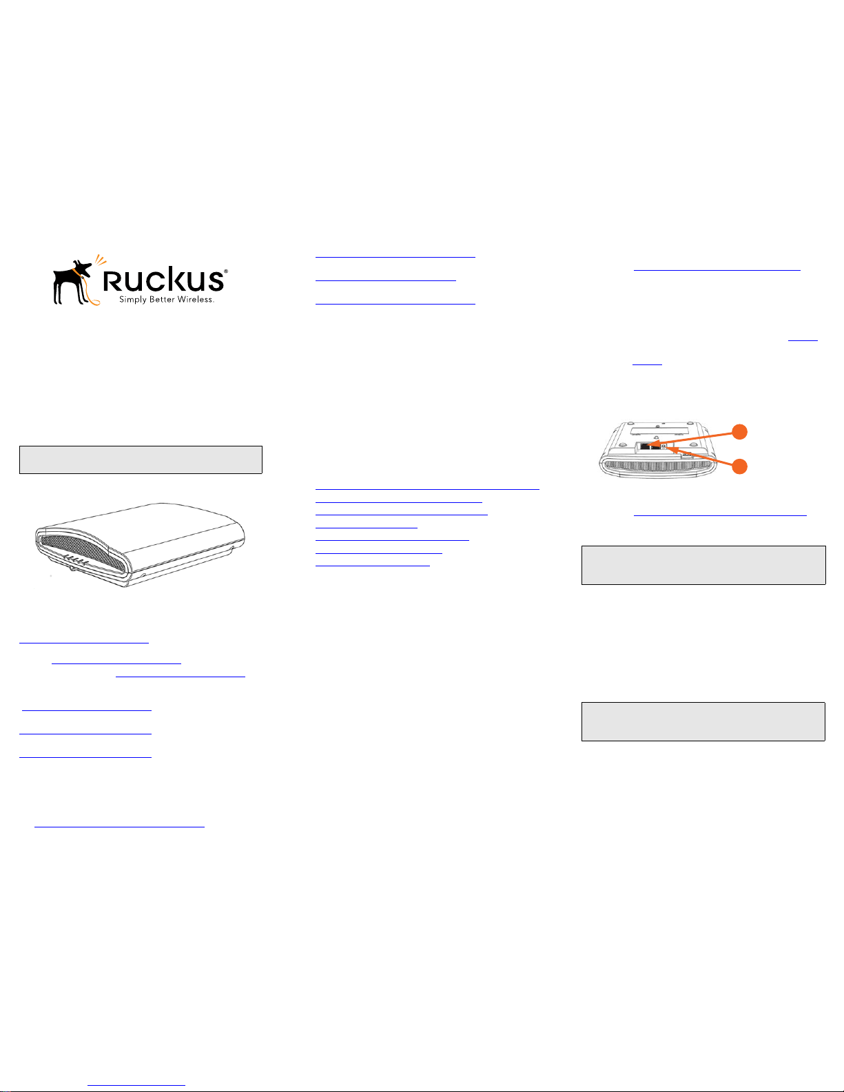
Figure 1. Ruckus Wireless R710 Access Point
This Guide in Other Languages
请从以下网站获得该指南的简体中文版
https://support.ruckuswireless.com
.
Vous trouverez la version française de ce guide à l'adresse
suivante https://support.ruckuswireless.com
.
こ のガ イ ド の日本語版 は https://support.ruckuswireless.com
でご覧くだ さい。
이 가이드의 한국어 버전은 웹 사이트
(https://support.ruckuswireless.com
) 에서 확인하시기 바랍니다 .
Veja a versão em português (Brasil) deste guia em
https://support.ruckuswireless.com.
Puede ver la versión en español (América Latina) de esta guía en
https://support.ruckuswireless.com.
Before You Begin
Before deploying Ruckus Wireless products, please check for the
latest software and the release documentation.
• User Guides and Release Notes are available at
http://support.ruckuswireless.com/documents
.
• Software Upgrades are available at
http://support.ruckuswireless.com/software
.
• Open Source information is available at
http://opensource.ruckuswireless.com
.
• Software License and Limited Warranty are available at
http://support.ruckuswireless.com/warranty
.
Package Contents
• R710 Access Point
• One T-bar mounting assembly kit, including:
• One T-bar bracket (2 separate plastic parts)
• Two each 1.0" L x No. 8 steel Phillips panhead mounting
screws and plastic wall anchors
• Regulatory flyer
• Product warranty statement
• Declaration of Conformity, if required
•This Quick Setup Guide
CONFIGURING THE AP
Continue with the following steps:
• Step 1: Collecting Setup Requirements, Hardware, and Tools
• Step 2: Connecting Your Computer to the AP
• Step 3: Preparing Your Computer for AP Setup
• Step 4: Logging Into the AP
• Step 5: Customizing the Wireless Settings
• Step 6: Placing the AP in Your Site
• Step 7: Verifying the Installation
Step 1: Collecting Setup Requirements,
Hardware, and Tools
• A computer running Windows 7 (procedures for common
operating systems are similar).
• One Cat 5e (or better) Ethernet cable.
• A Ruckus Wireless 902-0169-xx00 AC power adapter (sold
separately)
--OR-an 802.3at-compliant Power over Ethernet (PoE) switch or
PoE injector.
Optional hardware and tools:
• Customer-supplied small padlock with a 3.5mm (0.14”) or
smaller shackle, used to fasten the AP to the secure mounting
bracket or the T-bar bracket.
• Customer-ordered Ruckus Wireless 902-0120-0000 secure
mounting bracket kit:
• If you are mounting the AP on a flat surface using the
secure mounting bracket kit, then you need an electric drill
with 4.75mm (3/16”) drill bits.
• If you are mounting the AP on a pipe or pole using the
secure mounting bracket kit, then you will also need a
38.1mm to 63.5mm (1.5" to 2.5") pipe or pole, two
included stainless steel clamps, and hand tools to tighten
the clamps.
Continue with Step 2: Connecting Your Computer to the AP
.
Step 2: Connecting Your Computer to the AP
1 After removing your AP from its package, place it next to your
computer.
2 Using an Ethernet cable, connect your computer’s network
port to the 10/100/1000 POE In port on the AP (A in Figure 2
).
3 Using an AC adapter (sold separately), connect the AP 12VDC
port (B in Figure 2
) to a convenient (and protected) power
source.
Alternatively, connect the 10/100/1000 POE In port to a PoE
injector or switch for both power and network connectivity.
Figure 2. AP ports
4 Verify that the PWR LED on the AP is a steady green.
Continue with Step 3: Preparing Your Computer for AP Setup
.
Step 3: Preparing Your Computer for AP Setup
1 On your Windows 7 computer, configure your network
adapter from the Local Area Connection settings as follows:
• Start > Control Panel > Network and Sharing
Center > Change Adapter Settings
2 Edit the TCP/IPv4 address settings as follows:
• Local Area Connection > Properties > Internet
Protocol Version 4 (TCP/IPv4) > Properties
The Internet Protocol Version 4 (TCP/IPv4) Properties dialog
box appears.
3 Select Use the following IP address (if it is not already
selected) and then make the following entries:
• IP address: 192.168.0.22 (or any available address in the
192.168.0.x network, except 192.168.0.1)
• Subnet mask: 255.255.255.0
• Default gateway: 192.168.0.1
Leave the DNS server fields empty.
Note: The minimum software revision for the AP is base image
100.0.2 or later, RuckOS 3.2 or later, or ZoneFlex 9.12 or later.
Note: The following procedures assume that Windows 7 is the
operating system. Procedures for other operating systems are
similar.
Important! Write down all of the currently active settings so you
can restore your computer to its current configuration later
(when this process is complete).
A
B
Page 2
Copyright © 2015 Ruckus Wireless, Inc. Page 2 of 4
Published 10 February 2015, Part Number 800-70766-001 Rev B
4 Click OK to save your changes.
Your changes are put into effect immediately. Continue with Step
4: Logging Into the AP.
Step 4: Logging Into the AP
As specified in Step 3: Preparing Your Computer for AP Setup, the
computer should be directly connected to your AP through one of
the Ethernet ports and powered on, ready for setup.
1 On your computer, open a Web browser window.
2 In the browser, type this URL to connect to the AP:
https://192.168.0.1
3 Press <Enter> to initiate the connection. When a security
alert dialog box appears, click OK/Yes to proceed.
4 When the Ruckus Wireless Admin login page appears, enter
the following:
• Username: super
• Password: sp-admin
5 Click Login.
Continue with Step 5: Customizing the Wireless Settings
.
Step 5: Customizing the Wireless Settings
1 On the Web interface menu, click Configuration > Radio
2.4G or Configuration > Radio 5G. The Configure >
Wireless > Common page appears.
2 Verify that the following options are active:
• Channel: SmartSelect
• Country Code: If you are not located in the United States
of America, select your current country.
3 Click Update Settings if you made any changes.
4 Click any of the “Wireless #” (Wireless LAN Number) tabs at
the top of the page.
5 In Wireless Availability, click Enabled.
6 Delete the text in the SSID field, then type a name for your net-
work that will help your users identify this AP in their wireless
network connection application.
7 Click Update Settings to save your changes.
8 Repeat Step 4 through Step 7 for each Wireless # (Wireless
LAN Number) interface that you want to enable.
9 Click Logout to exit the Web interface.
10 When the Ruckus Wireless Admin login page reappears, you
can exit your browser.
11 Disconnect the AP from the computer and from the power
source, and then restore your computer to its original network
connection configuration.
Continue with Step 6: Placing the AP in Your Site
.
Step 6: Placing the AP in Your Site
1 Move the AP to its permanent location (accessible to both
power and network connections). Refer to Mounting Instruc-
tions for physical installation.
2 Use an Ethernet cable to connect the 10/100/1000 port to the
appropriate device:
• The ISP’s or carrier’s network device --or--
• The Ethernet switch that is connected to the ISP’s or
carrier’s network device.
3 Connect the AP power adapter (or PoE power supply) to the
AP, and then to a convenient power source.
4 Verify that the 10/100/1000 port LED is lit.
After a short pause to re-establish the Internet connection, you can
test the AP. Continue with Step 7: Verifying the Installation
.
Step 7: Verifying the Installation
1 Using any wireless-enabled computer or mobile device,
search for and select the wireless network you previously configured.
2 If you can connect, open a browser and link to any public Web
site.
Congratulations! Your wireless network is active and ready for use.
MOUNTING INSTRUCTIONS
The AP can be mounted to a drop-ceiling T-bar, flat surface, or a
pole using Ruckus Wireless AP mounting kits. Refer to the
following sections:
• Mounting on a Drop-Ceiling T-Bar
• Mounting on a Flat Surface
• Mounting on a Flat Surface or Pole Using the Optional Secure
Mounting Bracket
Mounting on a Drop-Ceiling T-Bar
The factory-supplied T-bar mounting assembly kit allows you to
attach the AP to recessed and flush drop-ceiling T-bars.
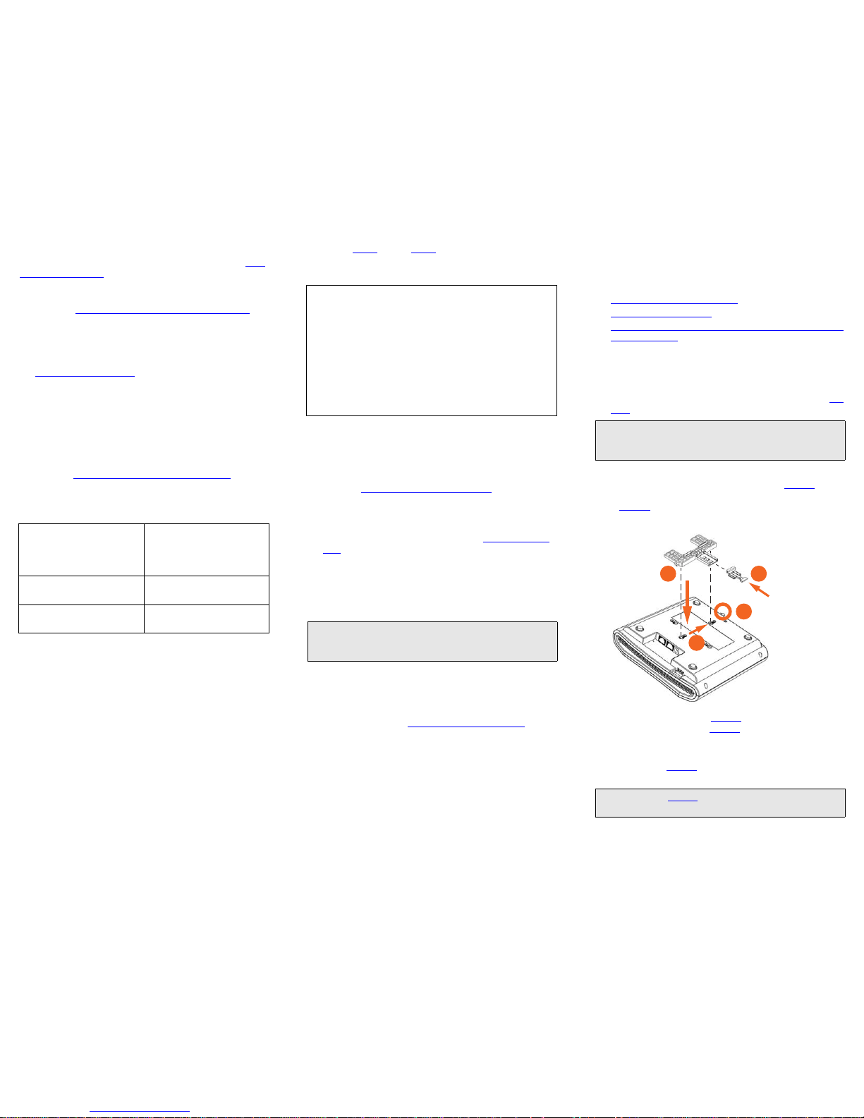
1 Position the studs on the bottom of the T-bar bracket (A in Fig-
ure 3) in the keyholes on the AP enclosure.
2 Slide the T-bar bracket away from the Ethernet ports on the
bottom of the AP until the AP retainer tab (B in Figure 3
) snaps
into place, trapping the T-bar bracket studs in the keyholes (C
in Figure 3
).
Figure 3. Attaching the T-bar bracket to the AP
3 Insert the locking tab (D in Figure 3) so it is in the first position
on the T-bar bracket (A in Figure 3
).
4 Gently push the ceiling tiles, if present, up and out of the way.
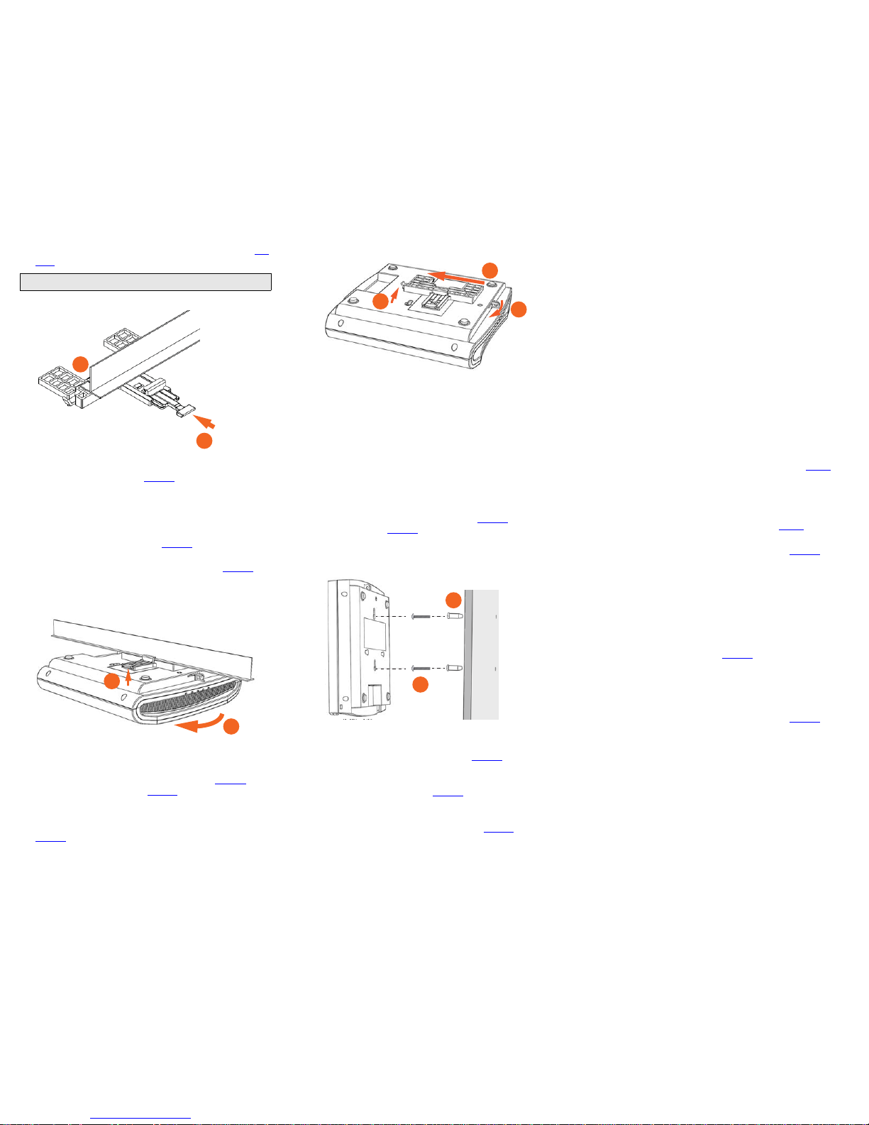
5 Position the T-bar bracket so its two clasps grip one edge of
the T-bar (A in Figure 4
). Make sure that both clasps are grip-
ping the T-bar.
Default AP Settings (for your reference)
Network Names (SSIDs) Wireless1—Wireless8 (2.4GHz
radio)
Wireless9—Wireless16 (5GHz
radio)
Security (Encryption method) Disabled for each wireless
interface
Default Management IP
Address
192.168.0.1
Optional: In a default R710 AP configuration, the AP uses a
DHCP-assigned IP address.
If you anticipate logging into the AP regularly to perform
monitoring or maintenance once it is in place, then you may want
to consider switching from DHCP and instead assigning a static
IP address to the AP.
A. On the menu, click Configuration > Internet.
B. Click the Static IP option.
C. Fill in the IP Address and Mask fields.
D. Click Update Settings to save your changes.
Note: If you will be using PoE, then you will need a Cat 5e (or
better) Ethernet cable to connect the AP to the PoE injector or
PoE switch.
Note: There is a second set of keyholes that are for optional
sideways mounting on a drop-ceiling T-bar. Physical security is
not supported when mounting the AP with this set of keyholes.
Note: For clarity, Figure 4 only shows the T-bar bracket and the
T-bar, and does not show the AP.
A
B
D
C
Page 3
Copyright © 2015 Ruckus Wireless, Inc. Page 3 of 4
Published 10 February 2015, Part Number 800-70766-001 Rev B
6 Hold the AP in place and gently push the locking tab (B in Fig-
ure 4) until its clasp grips the other edge of the T-bar.
Figure 4. Attaching the T-bar bracket to the T-bar
7 (Optional) Attach a customer-supplied padlock through the
bracket AP retainer tab (B in Figure 3
) to lock the AP to the T-
bar bracket studs.
When you are done, the AP is mounted.
Removing the AP from the T-bar:
1 Move the ceiling tiles, if present, out of the way.
2 Gently lift up the locking tab (A in Figure 5) by sliding your fin-
ger under the tab.
3 Rotate the AP- and-T-bar bracket assembly (B in Figure 5).
The AP- and-T-bar bracket assembly comes away from the Tbar.
Figure 5. Removing the AP and T-bar bracket from the T-bar
Removing the T-bar bracket from the AP:
1 If the AP is locked to the T-bar bracket, then remove the lock.
2 Gently lift up the T-bar bracket locking tab (A in Figure 6) and
push the AP retainer tab (B in Figure 6
) to the side at the same
time.
3 While lifting up the T-bar bracket locking tab and pushing the
AP retainer tab to the side, gently push the T-bar bracket (C in
Figure 6
) toward the Ethernet ports on the bottom of the AP
until the bracket detaches from the AP.
Figure 6. Removing the T-bar bracket from the AP
Mounting on a Flat Surface
The factory-supplied mounting screws and plastic wall anchors
allow you to attach the AP to a wall or ceiling.
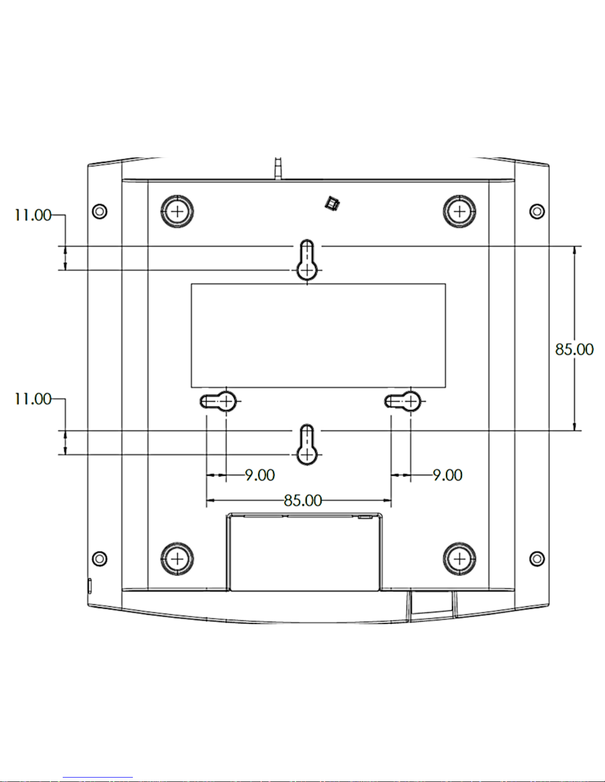
1 Use the Mounting Template on the last page of this Quick
Setup Guide to mark the locations for two drill holes on the
mounting surface. Note: There is a second set of keyholes
that are for optional sideways mounting on a flat surface.
Physical security is not supported when mounting the AP
with this set of keyholes.
2 Use a 4.75mm (3/16”) drill bit to drill holes approximately
25mm (1”) deep into the mounting surface.
3 Insert the factory-supplied anchors (A in Figure 7) and mount-
ing screws (B in Figure 7
) into the mounting surface, leaving
approximately 6 mm (1/4”) of the screw heads protruding for
the AP enclosure.
Figure 7. Flat surface mounting
4 Place the AP onto the mounting screws so that the screw
heads enter the keyholes on the AP enclosure, and push the
AP down until the AP retainer tab (B in Figure 6
) snaps into
place.
5 (Optional) Attach a customer-supplied padlock through the
integral AP retainer tab (B in Figure 6
) to lock the AP to the
mounting screw heads.
6 To remove the AP from the factory-supplied mounting screws,
push sideways on the AP retainer tab (B in Figure 6
), to unlock,
then push the AP up to release the AP enclosure from the
mounting screws.
Mounting on a Flat Surface or Pole Using the
Optional Secure Mounting Bracket
The customer-ordered Ruckus Wireless secure mounting bracket
kit (ordering part number 902-0120-0000) includes a metal
mounting bracket and provides greater security when attaching
the AP to flat surfaces (walls and ceilings) and to poles.
• If you are mounting the AP on a flat surface, then you will also
need an electric drill with a 4.75mm (3/16”) drill bit, and the
four No. 6 zinc plated screws and plastic wall anchors
included with the kit.
• If you are mounting the AP on a truss or pole, then you will
also need the two pipe clamps included with the kit.
Continue with the following:
1 If you are mounting the AP on a flat surface, then use the
secure mounting bracket as a template to mark the locations
for four drill holes on the mounting surface. There are four
screw holes available on the secure mounting bracket.
Fasten the bracket to the flat surface using four mounting
screws and plastic wall anchors and continue with Step 3
.
2 If you are mounting the AP on a pipe or pole, then feed the two
stainless steel clamps included with the kit through the slots
on the secure mounting bracket. Use common hand tools to
tighten the clamps around the pipe or pole.
After the bracket is attached, continue with Step 3
.
3 Insert the two studs on the secure mounting bracket into the
keyholes on the bottom of the AP, as shown in Figure 3
. Note:
There is a second set of keyholes that are for optional sideways mounting on a flat surface. Physical security is not supported when mounting the AP with this set of keyholes.
4 Slide the AP toward the Ethernet ports on the bottom of the
AP. The AP has a built-in lock for the secure mounting bracket
studs, and snaps into the locked position when the studs are
fully in the keyholes.
5 (Optional) Attach a customer-supplied padlock through the
integral AP retainer tab (B in Figure 6
) to fasten the AP to the
secure mounting bracket studs.
Removing the AP from the secure mounting bracket:
1 If the AP is locked to the secure mounting bracket, then
remove the lock.
2 Gently push and hold the AP retainer tab (B in Figure 6) to the
side to release the secure mounting bracket.
3 While holding the AP retainer tab to the side, slide the AP away
from the Ethernet ports on the bottom of the AP.
For More Information
You can now use the wireless network to log into the AP’s Web
interface. For information on how to configure the AP, refer to the
Ruckus Wireless Access Point User Guide, or refer to the
appropriate Ruckus Wireless AP controller or AP manager user
documents.
Note: Make sure that all three clasps are gripping the T-bar!
A
B
A
B
C
B
A
A
B
Page 4
Copyright © 2015 Ruckus Wireless, Inc. Page 4 of 4
Published 10 February 2015, Part Number 800-70766-001 Rev B
MOUNTING
TEMPLATE
 Loading...