


PREMIUMlinePREMIUMline
USE INSTRUCTION 115V
RS120e - RS140e

2
US I american
PRECISION TOOLS
Contents
Page
Technical data 4/5
Security instructions 6
Assembling, Application, Maintenance 7/8
Putting into operation 8
Drilling unit RS140e 8
Drawing of drilling unit RS120 9
Drawing of drilling mechanism RS120 10
Drawing of electrical system RS120 10
Spare parts list RS120 11/12
Drawing of drilling unit RS125e 13
Drawing of drilling mechanism RS125e 14
Drawing of electrical system RS125e 14
Spare parts list RS125e 15/16
Drawing of drilling unit RS126e 17
Drawing of drilling mechanism RS126e 18
Drawing of electrical system RS126e 18
Spare parts list RS126e 19/20
Drawing of drilling unit RS130e 21
Drawing of drilling mechanism RS130e 22
Drawing of electrical system RS130e 22
Spare parts list RS130e 23/24
Drawing of drilling unit RS140e 25
Drawing of drilling mechanism RS140e 26
Drawing of electrical system RS140e 26
Spare parts list RS140e 27/28
Connection diagramm RS120, RS 125e, RS130e, RS 140e 29
Guarantee 30
Declaration of conformity 30

3
US I american
PRECISION TOOLS
Standard fine adjustment stabilised
(
RS125e + RS140e)
• Displaceability: ± 5 mm
• Pivoting range: ± 5°
Fast and simple side change of the star grip.
The new RUKO plastic case with trolley enables
a safe and easy transport of RS125e + RS140e
machines. The trolley can be easily latched to
the case and removed again.
The RUKO fine adjustment enables repositioning with fixed magnets.
Better handling due to ergonomic
carrying handle.
Integrated coolant bottle with intelligent
coolant supply (filling quantity 750 ml).
Magnet with 18.000 N clamping force and larger
contact surface in models RS125e + RS140e.
The RUKO magnetic-stand drilling machines
RS125e - RS140e

4
1 3 5
0 2 4
L
R
kg
mm
+/- 5,0 mm
+/- 5,0 mm
US I american
PRECISION TOOLS
Subject to alterations and errors!
Technical data
Technical data RS120 RS125e RS126e
Article no.
108 0120 RS 108 0125 RS 108 0126 RS
Mag. clamping force: 18.000 N 18.000 N 13.000 N
Power consumption: 1.200 Watt 1.200 Watt 1.200 Watt
Gears: 2 gear 2 gear 2 gear
Rotation speeds r.p.m.: 250 / 450 r.p.m. 100-250 / 180-450 r.p.m. 100-250 / 180-450 r.p.m.
Electrical rotation controller:
Torque controller:
Right-left-handed rotation:
Height: 600,0 - 675,0 mm 600,0 - 675,0 mm 580,0 - 655,0 mm
Width: 240 x 108,0 mm 240 x 108,0 mm 230 x 108,0 mm
Weight: 23,0 kg 23,0 kg 19,0 kg
Lift: 200,0 mm 200,0 mm 200,0 mm
Adapter: Morse taper MT 2 Morse taper MT 2 Morse taper MT 2
Core drills: Ø 12,0 - 60,0 mm Ø 12,0 - 60,0 mm Ø 12,0 - 60,0 mm
Drill chuck: 3,0 - 16,0 mm 3,0 - 16,0 mm 3,0 - 16,0 mm
Twist drills DIN 338: max. Ø 16,0 mm max. Ø 16,0 mm max. Ø 16,0 mm
Twist drills DIN 1897: max. Ø 16,0 mm max. Ø 16,0 mm max. Ø 16,0 mm
Twist drills DIN 345: max. Ø 23,0 mm max. Ø 23,0 mm max. Ø 23,0 mm
Cutting depth core drills: up to 110,0 mm up to 110,0 mm up to 110,0 mm
Input voltage: 115 V 115 V 115 V
Conformity with: VDE, CEE VDE, CEE VDE, CEE
Moveable field: +/- 5,0 mm +/- 5,0 mm
Turn field: +/- 5° +/- 5°
Thread cutting:
Accessoires RS120 RS125e RS126e
Plastic tool case
+ trolley
Plastic tool case
+ trolley
Plastic tool case
Drill drift Drill drift Drill drift
Safety belt Safety belt Safety belt
Drill chuck, Art. no. 108 117
3,0 - 16,0 mm
Drill chuck, Art. no. 108 117
3,0 - 16,0 mm
Drill chuck, Art. no. 108 117
3,0 - 16,0 mm
Coolant bottle + sprayer Coolant bottle + sprayer Coolant bottle + sprayer
Protective work gloves Protective work gloves Protective work gloves
Safety goggles Safety goggles Safety goggles
Ear protectors Ear protectors Ear protectors
EasyLock, Art. no. 108 317 EasyLock, Art. no. 108 317 EasyLock, Art. no. 108 317

5
RS120
RS126e
RS125e
RS130e
RS140e
135
024
L
R
kg
mm
+/- 5,0 mm
+/- 5,0 mm
US I american
PRECISION TOOLS
Subject to alterations and errors!
Technical data
Technical data RS130e RS140e
Article no.
108 0130 RS 108 0140 RS
Mag. clamping force: 18.000 N 18.000 N
Power consumption: 1.840 Watt 1.840 Watt
Gears: 2 gear 4 gear
Rotation speeds r.p.m.: 40-120 / 160-450 U/min
40-120 / 70-180 /
160-450 / 300-700 U/min
Electrical rotation controller:
Torque controller:
Right-left-handed rotation:
Height: 600,0 - 680,0 mm 600,0 - 680,0 mm
Width: 240 x 108,0 mm 240 x 108,0 mm
Weight: 26,0 kg 26,0 kg
Lift: 200,0 mm 200,0 mm
Adapter: Morse taper MT 3 Morse taper MT 3
Core drills: Ø 12,0 - 100,0 mm Ø 12,0 - 100,0 mm
Drill chuck: 3,0 - 16,0 mm 3,0 - 16,0 mm
Twist drills DIN 338: max. Ø 16,0 mm max. Ø 16,0 mm
Twist drills DIN 1897: max. Ø 16,0 mm max. Ø 16,0 mm
Twist drills DIN 345: max. Ø 31,5 mm max. Ø 31,5 mm
Cutting depth core drills: up to 110,0 mm up to 110,0 mm
Input voltage: 115 V 115 V
Conformity with: VDE, CEE VDE, CEE
Moveable field: +/- 5,0 mm +/- 5,0 mm
Turn field: +/- 5° +/- 5°
Thread cutting:
Accessoires RS130e RS140e
Plastic tool case
+ trolley
Plastic tool case
+ trolley
Drill drift Drill drift
Safety belt Safety belt
Drill chuck, Art. no. 108 117
3,0 - 16,0 mm
Drill chuck, Art. no. 108 117
3,0 - 16,0 mm
Coolant bottle + sprayer Coolant bottle + sprayer
Protective work gloves Protective work gloves
Safety goggles Safety goggles
Ear protectors Ear protectors
EasyLock, Art. no. 108 318 EasyLock, Art. no. 108 318

6
US I american
PRECISION TOOLS
The drilling units may only be used according to their determination. The use of the drilling unit as a lifting magnet is dangerous and absolutely
inadmissible. The use for another purpose than what is determined endagers people and the machine.
Please note also the following safety instructions for electric tools.
Attention: Before the use of electric tools please note the following basic safety instructions to avoid electric shock, injuries and fire.
Read and follow these instructions before using the electric tool.
1. Keep your working area tidy.
A working area that is not cleared up causes danger of accidents.
2. Consider external influences.
Do not expose electric tools to rain. Do not use electric tools in damp or wet surroundings. Good lighting is important.
Do not use electric tools near inflammable fluids or gases.
3. Protect yourself from electric shock.
Avoid body contact to earthed parts like pipes, radiators, ovens, fridges.
4. Keep away from children.
Do not let other people touch the tool or the cable - keep them from your working area.
5. Keep your electric tools in a safe place.
Unused tools should be kept in a dry, closed space out of the reach of children.
6. Do not overload your electric tools.
You will work better and safer within the indicated power range.
7. Use the right tool.
Do not use tools week in power for heavy strains.
Do not use tools for purposes other than determined, e.g. do not use a circular saw for felling a tree or cutting branches.
8. Use suitable working clothes.
Do not wear loose clothing or jewelry. They could be caught by moving parts of the tool.
If you are working outdoors it is recommendable to wear rubber gloves and non-slipping shoes. If you have long hair wear a hair-net.
9. Use protective goggles.
Also use a breathing mask when carrying out work that produces dust.
10. Do not use the cable for other purposes.
Do not use the cable for carrying the tool and do not use it to pull the plug out of the socket. Protect the cable from heat, oil and cutting edges.
11. Secure your workpiece. Use a fastening device or a vise to fix the workpiece.
The workpiece is better fixed than by hand and it makes it possible to use the tool with both hands.
12. Do not lean too far over the machine.
Take care to keep a normal position. You should have a secure standing position and you should keep your balance.
13. Maintain your tools carefully.
Keep your tools sharp and clean - working with them will be better and safer. Follow the maintenance instructions and indications concerning
the replacement of tools. Check the cable regularly and in case of damage let it replace by an expert. Also check extension cables regularly
and replace them if they are damaged.Keep handles dry and free from oil and grease.
14. Pull the plug out of the socket.
If you do not use the machine, before maintenance, while changing tools like saw blades, drills or any kind of machine tools.
15. Remove tool keys.
Before turning the machine on, make sure that all keys and adjustment tools are removed.
16. Avoid turning on the machine inadvertently.
Do not carry tools that are plugged in with your finger on the switch. Make sure the switch is on „off“ position while plugging in the tool.
17. Extension cables outdoors.
Only use extension cables that are authorized to be used outdoors and that are accordingly marked.
18. Always take care.
Control your work. Be sensible and do not use the tools when you have difficulties in concentrating.
19. Check if your appliance shows damages.
Before further use of the tool please check if safety appliances or damaged parts are working correctly.
Check if the moving parts function correctly, if they move without problems, if no parts are broken, if all other parts are fixed correctly and if
all other conditions that influence the working of the machine are fulfilled. If the use instruction does not say otherwise the damaged safety
appliances and parts should be either repaired or replaced correctly. Damaged switches have to be replaced. Do not use tools where the
switches cannot be set to „on“ or „off“.
20. Attention!
For your own safety only use accessories and attachments that are indicated in the use instruction or are offered in the according catalogue.
The use of tools or accessories other than recommended by the use instruction may be dangerous.
21. Repairs should be carried out only by experts
Electric tools are subject to the according safety regulations.
Repairs may only be carried out by an expert, otherwise the user runs the risk of accidents.
Please keep these instructions carefully.
Attention: Please read this manual carefully before using the drilling unit

7
US I american
PRECISION TOOLS
The magnetic drilling units are supplied with a high powered electromagnet as well as a reclosure preventing device for the drilling mechanism. The
magnetic drilling units correspond to protection class I with conductor according to IEC 745. The drilling mechanisms that have been developed
according to DIN VDE 0740 and IEC 745-1 are radio screened according to EN 55014 and EN 61000 and are designed for continous operation: It is
possible that the sound level exceeds 85 dB (A): In this case special sound protection is necessary for the user. Indications concerning the sound
level of the drilling units are based on DIN 45 649 part 2, DIN 45 635 part 21 and DIN EN 27 574 (ISO 7574).
The precise adjustment allows an exact adjustment of the drilling tool within the movable field. The adjustable dovetail guidance with wear resisting brass
guide beads allows a precise guidance of the drilling mechanism. This ensures light and regular feed.The drill feed is made manually with the handle.
Application of the drilling unit RS5e, RS10, RS25e, RS40e
The magnetic drilling units are designed for drilling and thread cutting (with reversing adapter) on workpieces with magnetic properties for horizontal, vertical or overhead work. These drilling units with their rectangular footing are especially adapted for drilling in structural steel. The drilling unit
should be placed on an even spot on the workpiece. This spot may be unworked. Loose rust and cinder as well as varnish and flat coats have to be
removed. If material thinner than 1/2” (12.0 mm) is drilled, a steel plate should be put under the workpiece to reinforce the magnetic power.
Never put the running magnetic drilling unit on insulating material (e.g. wood, concrete, etc.). The insufficient heat dissipation may cause overheating
and destruction of the electromagnet. Be aware that the magnetic clamping force is not retained after an interruption of the electricity supply
(power failure, pulling of the plug). The magnetic drilling units may not be used while arc welding is carried out on the workpiece. The welding current
could damage the magnetic drilling unit.
The magnetic drilling units have a locking device that prevents the machine from starting automatically. This locking device ensures that after pressing the red switch only the electromagnet is supplied with electricity. The drilling mechanism is only supplied with electricity after pressing the green
switch. It is only now that the drilling mechanism can work.
If the electricity supply is interrupted (caused for example by a damaged supply line or by pressing the red switch) the drilling mechanism remains
without electricity even after the interruption is over or the red switch has been pressed again. To supply the drilling mechanism with eletricity again
you have to press the green switch once more. The drilling mechanism starts working.
Maintenance
Damaged parts have to be replaced by original spare parts. All gliding surfaces have to be oiled quarterly after cleaning. Lateral play can be balanced
by adjusting the set screws. For optimal cooling the ventilating valves of the drilling mechanism have to be kept free from dirt and dust.
Please note that electric devices may only be repaired, maintained and checked by electric experts, as improper repairs can endanger the user!
For ordering spare parts it is necessary to indicate our order number or to send us a sample and indicating the serial number, machine type and
voltage.
Assembling

8
US I american
PRECISION TOOLS
Plug the cable into a suitable supply. Check the correct voltage!
If you are using an extension cable please check if it is suitable for the machine`s rated input power!
Attention: For vertical and overhead drilling work it is absolutely necessary to wear the enclosed safety belt.
Putting into operation
Position the drill bit over the drilling point. Switch the magnetic drilling unit on by pressing the red switch. The magnetic field that is created keeps the
drilling unit clamped to the workpiece. Before drilling check if the magnetic drilling unit clamps safely to the workpiece.
Magnetic drilling units with the possibilty of precise adjustment (see technical data) allow an exact positioning of the drill bit even after the electromagnet has been switched on. For this it is necessary to loosen the lever of the precise adjustment device. The drilling mechanism can now be
moved and adjusted on the electromagnet. After the drill bit has been adjusted the lever is fastened and the adjusted position is fixed. With machines
with more than one gear adjust the rotation speed of the engine according to the tool to be used.
Attention: Change rotation speeds only when the drilling mechanism is not working! The speeds are indicated by a single or double symbols on the changeover switch. The changeover can be helped by gently turning the work spindle by hand. For drill drive units which also have
electronic speed controllers, the speed and power (torque) can be continuously adjusted at the corresponding controller on the drill drive unit.
Note: also read and follow the additional information provided under Drill drive type RS 40e.
For drill drive units with electronic speed controllers, the speed is adjusted at the corresponding set wheel on the control panel of the drill stand.
For drill drives with the forward and reverse feature (types RS 40e only) the direction is changed via the black switch on the control panel of the drill
stand. Position „R“ is for clockwise and Position „L“ is for the anticlockwise rotation. Note: The direction of rotation must only be changed when the
drill drive is switched off. The switch is for turning on the drilling mechanism (green light up ON).
Please note: The drilling mechanism can only be started after the electromagnet has been switched on. Drill feed is made manually by moving the
handles.To avoid overloading of the magnetic drilling unit or to avoid premature wear of the tool it is necessary to adjust the drilling pressure. After
each cut chips and/or drilling cores have to be removed. Cooling/lubrication has to be made according to the tool used. Please take care to use not
more cooling/lubrication paste than necessary and that it does not get into the drilling mechanism.
After usage the magnetic drilling units should be stored in a vertical position so that the gear oil may spread evenly.
Drillling unit RS140e
Function and mode of effect of the electronic module. Essentially, the electronics have three main tasks to fulfil:
1. protecting the operator against accidents
2. securing a long service life of the drill drive and the tools
3. infinite speed adjustment to match the technical requirement in question
An adjustable torque limitation set on the Power controller grants the operator accident protection to a very great extent and the greatest possible
gentle treatment for the drill drive. In controller position 3-4, the integrated electronics automatically switch off when the nominal torque is exceeded.
In controller position 1, about 0.3 times the nominal torque becomes active, in controller position 7 about 2.1 times.
The torques resulting in controller positions 4-7 are intended for cases of short-term overloads. In such cases of application, drill drive
must be operated with increased care. If the pre-selected torque is exceeded in drilling, the drill drive is switched off by the electronics.
The drill drive starts again by removing the load. If the drill drive does not start again immediately, the thermal overload protection has
become effective at the same time. It prevents exceeding of the admissible coil temperature with large torques or a reduced speed.
Switch the drill drive „off“ on the combined motor switch. After sufficient cooling of the coil, work can be continued by pressing the „on“ combined
motor switch.
After switching on again, we recommend operating the drill drive at top speed and idling for a short period, in order to achieve maximum cooling.
The required speed can be set infinitely between minimum and maximum on the „speed“ controller according to Diagram 2. Level 7 corresponds
to the nominal speed of the switched transmission gear in question. The selected speed does not change under load, which has a very favourable
effect on the service life of the tool.
For drill drives with clockwise/anti-clockwise movement, the direction of rotation can be changed by means of a change-over switch.
The change-over switch may only be operated with the drill drive at a standstill. The pre-selection of the size or the limitation of the torque is to be
done taking the technical and industrial safety requirements in the implementation of the work task into account.
Before putting into operation

9
60
1
70
1
57
2
48
1
69
1
58
1
67
1
39
1
33
2
61
1
64
1
63
1
32
1
42
1
41
1
40
1
43
1
44
1
45
1
36
1
30
1
31
4
46
1
47
1
72
1
73
1
74
1
52
1
56
1
71
1
53
1
37
1
38
2
68
1
75
3
59
1
62
1
51
1
54
4
34
4
35
4
65166
1
50
1
49
2
55
1
B2
2
B1
1
US I american
PRECISION TOOLS
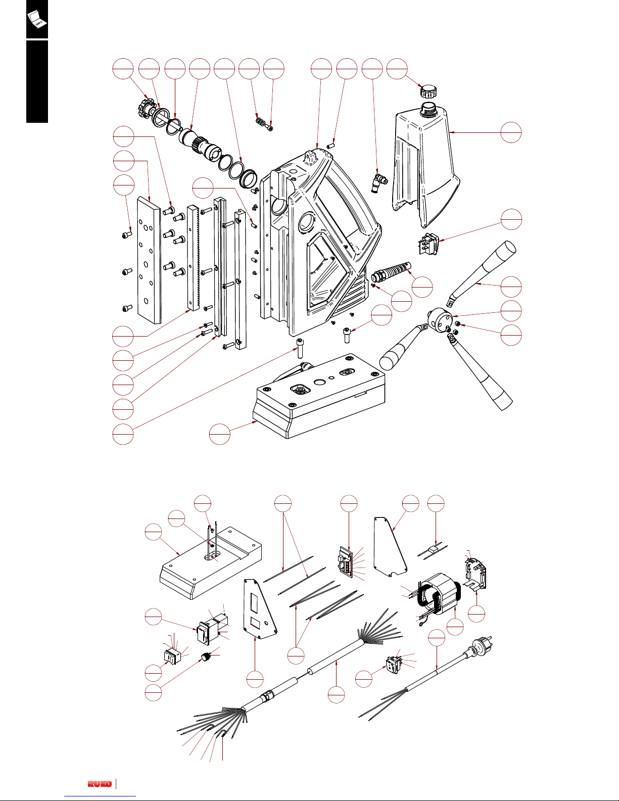
Drawing of drilling mechanism RS120

10
21
6
6
2
7
1
4
1
5
2
3
1
27
1
20
2
17
1
2
1
1
1
29
6
15
1
13
1
24
1
26
1
28
3
11
10
8
4
23
1
16
1
19
3
18
3
10
3
9
1
25
1
22
2
14
1
12
1
M-
M+
MO A2
MO 21
MO 11
MO 12
MO 22
MA 2
MA 2a
MA 1a
MA 1
1
2
1
2
MA 1a
MA 2a
SL
M
SL
M
B2
B1
M2
M1
M+
M-
B2
MO A2
MA 2
M1
MO 11
M2
MA 1
MO 21
B1
MO 12
MO 22
C 1
C 2
PR 1
PR 2
C 1
C 2
PR 2
PR 1
81
1
76
1
84
1
82
1
83
1
78
1
77
1
80
1
79
1
81
1
85
1
16
1
86
1
37
1
US I american
PRECISION TOOLS
Drawing of drilling unit RS120
Drawing of electrical system RS120

11
US I american
PRECISION TOOLS
Drilling unit RS120
Drilling mechanism RS120
Pos. Description Article no. Quantity
1 Machined body + brass plate 711 2 200 1
2 Spring plunger 711 4 007 1
3 Pinion shaft 711 3 217 1
4 Star grip with threaded rod 711 4 003 1
5 Bearing bowl 711 3 212 2
6 Safety ring 611 9 306 2
7 Balance plate 611 9 813 1
8 Threaded pin M5x12 611 9 004 4
9 Cylinder head screw M5 x 10 611 9 024 1
10 Toothed disc 5.3 mm 611 9 405 3
11 Hexagon socket screw M3x8 611 9 045 10
12 Cable gland 611 9 854 1
13 Cool bottle 711 4 013 1
14 Lid for cool bottle 108 1 01-4 1
15 Connection cooling 711 4 010 1
16 Switch magnet 611 4 402 1
17 Adapter for handle 711 3 216 1
18 Hand lever compl. 711 4 016 3
19 Set screw with flat point M8x8 611 9 043 3
20 Guide rail 611 3 228 2
21 Cylinder head screw M5x20 611 9 002 6
22 Cylinder head screw M3x20 711 4 001 2
23 Cylinder head screw M8x30 611 9 034 1
24 Cylinder head screw M8x20 611 9 063 1
25 Magnet + fine adjustment compl. 711 1 001 1
26 Carriage 711 3 218 1
27 Toothed rack 611 3 222 1
28 Cylinder head screw M6x12 611 9 026 3
29 Cylinder head screw M8x16 611 9 020 6
Pos. Description Article no. Quantity
30 Motor cover 711 2 005 1
31 Screw 3,9x50 611 3 504 4
32 Strain relief bushing 711 2 014 1
33 Carbon brush, cpl. 6.3x10x18 L82F10 611 2 551 2
34 Cold-forming tapping screw ZM4x12 611 1 530 4
35 Corrugated spring washer B4 611 1 533 4
B2 Pocket brush holder, cpl. 611 1 528 2
36 Motor housing 711 2 004 1
37 Pole ring, cpl. 711 2 018 1
38 Tapping screw C 3.9x60 611 1 531 2
39 Grooved dowel pin 4x12 611 3 215 1
40 Gearbox seal 611 1 501 1
41 Gear bearing plate 711 2 007 1
42 Air guide ring 711 2 009 1
43 Circlip 11/1 611 2 519 1
44 Grooved ball bearing 6001 2RS 711 2 017 1
45 Circlip 28/1.2 611 1 524 1
B1 Armature, cpl. - 115 V 711 2 016 1
46 Grooved ball bearing 608 2Z 611 1 526 1
47 O-ring 22x2.5 611 1 527 1
48 Disc 711 2 001 1
49 Shaft sealing ring 25x40x7 711 2 002 2
50 Work spindle 711 2 012 1
51 Feather key A5x5x12 611 2 518 1
52 Grooved ball bearing 6904 2RS 611 2 529 1
53 Connection cooling 611 3 515 1
54 PT screw 50x35 711 2 003 4

12
US I american
PRECISION TOOLS
Pos. Description Article no. Quantity
76 Magnet - 1
77 DIN 6797 - M4 611 9 402 1
78 DIN 7984 - M4 x 6 611 9 016 1
79 Front cover 711 2 401 1
80 Motor switch - 115 V 611 2 574 1
81 Cables motor switch-magnet switch-plate 611 1 413 1
82 Circuitboard 711 1 405 1
83 Back cover 711 2 402 1
84 Cable motor switch-plate 611 1 416 1
85 Motor cable 711 1 420 1
86 Main cable - GB 611 1 410 + 611 1 425 1
86 Main cable - USA 611 1 409 1
Electrical system RS120
Pos. Description Article no. Quantity
55 Gear housing 711 2 008 1
56 T piece 711 4 002 1
57 Cylinder head screw M3x20 711 4 001 2
58 Spring plunger Ø 6 611 2 531 1
59 Control button 711 2 006 1
60 Grooved ball bearing 6203 2RS 611 1 508 1
61 Adjusting washer 15/22x0.2 611 2 521 1
62 Spindle wheel 45 teeth 611 2 520 1
63 Circlip 15/1 611 2 525 1
64 Grooved ball bearing 608 611 2 524 1
65 Pressure piece M8x18 resilient 611 3 520 1
66 Shaft with 2 pinions 611 2 528 1
67 Sleeve 4x7x16 711 2 010 1
68 Screw M4x20 611 2 514 1
69 Coupling bolts, cpl. 611 2 526 1
70 Intermediate wheel 34 teeth 711 2 013 1
71 Grease chamber bulkhead 611 2 513 1
72 Feather key A5x5x28 611 2 517 1
73 Shaft for gear cluster 13 teeth 611 2 523 1
74 Gear cluster 34/40 teeth 611 2 527 1
75 Needle sleeve HK0810 611 1 521 3
Drilling mechanism RS120

13
65
1
75
1
62
2
53
1
67
1
73
1
72
1
41
1
33
1
50
1
66
1
70
1
68
1
34
1
44
1
43
1
42
1
45
1
46
1
47
1
38
1
32
2
48
1
51
1
49
1
78
1
57161
1
76
1
58
1
39
1
40
2
71
1
64
1
56
1
59
4
37
4
35
2
30
1
31
4
54
2
80
3
36
4
77
1
52
2
79
1
63
1
74
1
69
1
55
1
B2
2
60
1
B1
1
US I american
PRECISION TOOLS
Drawing of drilling mechanism RS125e
14
21
6
6
2
7
1
4
1
5
2
3
1
27
1
20
2
17
1
2
1
1
1
29
6
15
1
13
1
24
1
26
1
28
3
11
10
8
4
23
1
16
1
19
3
18
3
10
3
9
1
25
1
22
2
14
1
12
1
M-
M+
MO A2
MO 21
MO 11
MO 12
MO 22
MA 2
MA 2a
MA 1a
MA 1
SP 1
SP 2
LR 1a
LR 1
LR 1b
LR 2b
LR 2a
LR 2
1
2
3
4
5
6
7
8
1
2
3
4
5
6
7
8
MA 1a
MA 2a
SL
M
SL
M
B2
B1
M2
M1
M+
M-
B2
MO A2
MA 2
M1
MO 11
M2
MA 1
MO 21
B1
MO 12
MO 22
SP 1
SP 2
LR 1a
LR 2b
LR 2
LR 1b
LR 2a
LR 1
MP 1
MP 2
MP 4
C 1
C 2
MP 1
MP 2
C 1
C 2
MP 3
MP 4
PR 1
PR 2
PR 3
PR 4
PR 4
PR 3
PR 2
PR 1
blau
blau
grün
grün
MP 3
81
1
82
1
83
1
88
1
89
1
90
1
91
1
85
1
86
1
87
1
84
1
88
1
92
1
16
1
93
1
39
1
33
1
US I american
PRECISION TOOLS
Drawing of drilling unit RS125e
Drawing of electrical system RS125e

15
US I american
PRECISION TOOLS
Drilling unit RS125e
Drilling mechanism RS125e
Pos. Description Article no. Quantity
1 Machined body + brass plate 711 2 200 1
2 Spring plunger 711 4 007 1
3 Pinion shaft 711 3 217 1
4 Star grip with threaded rod 711 4 003 1
5 Bearing bowl 711 3 212 2
6 Safety ring 611 9 306 2
7 Balance plate 611 9 813 1
8 Threaded pin M5x12 611 9 004 4
9 Cylinder head screw M5 x 10 611 9 024 1
10 Toothed disc 5.3 mm 611 9 405 3
11 Hexagon socket screw M3x8 611 9 045 10
12 Cable gland 611 9 854 1
13 Cool bottle 711 4 013 1
14 Lid for cool bottle 108 1 01-4 1
15 Connection cooling 711 4 010 1
16 Switch magnet 611 4 402 1
17 Adapter for handle 711 3 216 1
18 Hand lever compl. 711 4 016 3
19 Set screw with flat point M8x8 611 9 043 3
20 Guide rail 611 3 228 2
21 Cylinder head screw M5x20 611 9 002 6
22 Cylinder head screw M3x20 711 4 001 2
23 Cylinder head screw M8x30 611 9 034 1
24 Cylinder head screw M8x20 611 9 063 1
25 Magnet + fine adjustment compl. 711 1 001 1
26 Carriage 711 3 218 1
27 Toothed rack 611 3 222 1
28 Cylinder head screw M6x12 611 9 026 3
29 Cylinder head screw M8x16 611 9 020 6
Pos. Description Article no. Quantity
30 Motor cap 711 2 005 1
31 Screw 3.9x50 611 3 504 4
32 Tapping screw HC 2.9x13 711 2 504 2
33 PCB - 115 V 611 2 556 1
34 Strain relief bushing 711 2 014 1
35 Carbon brush, cpl. 6.3x10x18 L85F13 711 2 503 2
36 Cold-forming tapping screw ZM4x12 611 1 530 4
37 Corrugated spring washer B4 611 1 533 4
B2 Pocket brush holder, cpl. 611 1 528 2
38 Motor housing 711 2 004 1
39 Pole ring, cpl. 711 2 501 1
40 Tapping screw C 3.9x60 611 1 531 2
41 Grooved dowel pin 4x12 611 3 215 1
42 Gearbox seal 611 1 501 1
43 Gear bearing plate 711 2 007 1
44 Air guide ring 711 2 009 1
45 Circlip 11/1 611 2 519 1
46 Grooved ball bearing 6001 2RS 711 2 017 1
47 Circlip 28/1.2 611 1 524 1
B1 Armature, cpl. - 115 V 711 2 506 1
48 Grooved ball bearing 608 2Z 611 1 526 1
49 Press board disc 611 1 550 1
50 Magnetic disc 611 1 551 1
51 O-ring 22x2.5 611 1 527 1
52 Carbon support strand 711 2 505 2
53 Disc 711 2 001 1
54 Shaft sealing ring 25x40x7 711 2 002 2

16
US I american
PRECISION TOOLS
Pos. Description Article no. Quantity
81 Magnet - 1
82 DIN 6797 - M4 611 9 402 1
83 DIN 7984 - M4 x 6 611 9 016 1
84 Front panel 711 2 405 1
85 Motor switch - 115 V 611 2 574 1
86 L/R switch 611 4 404 1
87 Speed controller 611 4 405 1
88 Cable set motor switch/solenoid switch/circuit board 611 1 413 1
89 Circuit board 711 1 405 1
90 Rear plate 711 2 406 1
91 Cable set capacitor motor 611 3 416 1
92 Motor cable 711 2 420 1
93 Main cable - GB 611 1 410 + 611 1 425 1
93 Main cable - USA 611 1 409 1
Pos. Description Article no. Quantity
55 Work spindle 711 2 012 1
56 Feather key A5x5x12 611 2 518 1
57 Grooved ball bearing 6904 2RS 611 2 529 1
58 Connection cooling 611 3 515 1
59 PT screw 50x35 711 2 003 4
60 Gear housing 711 2 008 1
61 T piece 711 4 002 1
62 Cylinder head screw M3x20 711 4 001 2
63 Spring plunger Ø 6 611 2 531 1
64 Control button 711 2 006 1
65 Grooved ball bearing 6203 2RS 611 1 508 1
66 Adjusting washer 15/22x0.2 611 2 521 1
67 Spindle wheel 45 teeth 611 2 520 1
68 Circlip 15/1 611 2 525 1
69 Pressure piece M8x18 resilient 611 3 520 1
70 Grooved ball bearing 608 611 2 524 1
71 Screw M4x20 611 2 514 1
72 Sleeve 4x7x16 711 2 010 1
73 Coupling bolts, cpl. 611 2 526 1
74 Shaft with 2 pinions 611 2 528 1
75 Intermediate wheel 34 teeth 711 2 013 1
76 Grease chamber bulkhead 611 2 513 1
77 Shaft for gear cluster 13 teeth 611 2 523 1
78 Feather key A5x5x28 611 2 517 1
79 Gear cluster 34/40 teeth 611 2 527 1
80 Needle sleeve HK0810 611 1 521 3
Drilling mechanism RS125e
Electrical system RS125e

17
65
1
75
1
62
2
53
1
67
1
73
1
72
1
41
1
33
1
50
1
66
1
70
1
68
1
34
1
44
1
43
1
42
1
45
1
46
1
47
1
38
1
32
2
48
1
51
1
49
1
78
1
57161
1
76
1
58
1
39
1
40
2
71
1
64
1
56
1
59
4
37
4
35
2
30
1
31
4
54
2
80
3
36
4
77
1
52
2
79
1
63
1
74
1
69
1
55
1
B2
2
60
1
B1
1
US I american
PRECISION TOOLS
Drawing of drilling mechanism RS126e

18
21
6
6
2
7
1
4
1
5
2
3
1
27
1
20
2
17
1
2
1
1
1
29
6
15
1
13
1
26
1
28
3
11
10
8
4
23
1
16
1
19
3
18
3
1039
1
22
2
14
1
12
1
1
24
1
25
M-
M+
MO A2
MO 21
MO 11
MO 12
MO 22
MA 2
MA 2a
MA 1a
MA 1
SP 1
SP 2
LR 1a
LR 1
LR 1b
LR 2b
LR 2a
LR 2
1
2
3
4
5
6
7
8
1
2
3
4
5
6
7
8
MA 1a
MA 2a
SL
M
SL
M
B2
B1
M2
M1
M+
M-
B2
MO A2
MA 2
M1
MO 11
M2
MA 1
MO 21
B1
MO 12
MO 22
SP 1
SP 2
LR 1a
LR 2b
LR 2
LR 1b
LR 2a
LR 1
MP 1
MP 2
MP 4
C 1
C 2
MP 1
MP 2
C 1
C 2
MP 3
MP 4
PR 1
PR 2
PR 3
PR 4
PR 4
PR 3
PR 2
PR 1
blau
blau
grün
grün
MP 3
81
1
82
1
83
1
88
1
89
1
90
1
91
1
85
1
86
1
87
1
84
1
88
1
92
1
16
1
93
1
39
1
33
1
US I american
PRECISION TOOLS
Drawing of drilling unit RS126e
Drawing of electrical system RS126e

19
US I american
PRECISION TOOLS
Drilling unit RS126e
Drilling mechanism RS126e
Pos. Description Article no. Quantity
1 Machined body + brass plate 711 2 200 1
2 Spring plunger 711 4 007 1
3 Pinion shaft 711 3 217 1
4 Star grip with threaded rod 711 4 003 1
5 Bearing bowl 711 3 212 2
6 Safety ring 611 9 306 2
7 Balance plate 611 9 813 1
8 Threaded pin M5x12 611 9 004 4
9 Cylinder head screw M5 x 10 611 9 024 1
10 Toothed disc 5.3 mm 611 9 405 3
11 Hexagon socket screw M3x8 611 9 045 10
12 Cable gland 611 9 854 1
13 Cool bottle 711 4 013 1
14 Lid for cool bottle 108 1 01-4 1
15 Connection cooling 711 4 010 1
16 Switch magnet 611 4 402 1
17 Adapter for handle 711 3 216 1
18 Hand lever compl. 711 4 016 3
19 Set screw with flat point M8x8 611 9 043 3
20 Guide rail 611 3 228 2
21 Cylinder head screw M5x20 611 9 002 6
22 Cylinder head screw M3x20 711 4 001 2
23 Cylinder head screw M8x30 611 9 034 1
24 Cylinder head screw M8x20 611 9 063 1
25 Magnet + fine adjustment compl. 711 1 001 1
26 Carriage 711 3 218 1
27 Toothed rack 611 3 222 1
28 Cylinder head screw M6x12 611 9 026 3
29 Cylinder head screw M8x16 611 9 020 6
Pos. Description Article no. Quantity
30 Motor cap 711 2 005 1
31 Screw 3.9x50 611 3 504 4
32 Tapping screw HC 2.9x13 711 2 504 2
33 PCB - 115 V 611 2 556 1
34 Strain relief bushing 711 2 014 1
35 Carbon brush, cpl. 6.3x10x18 L85F13 711 2 503 2
36 Cold-forming tapping screw ZM4x12 611 1 530 4
37 Corrugated spring washer B4 611 1 533 4
B2 Pocket brush holder, cpl. 611 1 528 2
38 Motor housing 711 2 004 1
39 Pole ring, cpl. 711 2 501 1
40 Tapping screw C 3.9x60 611 1 531 2
41 Grooved dowel pin 4x12 611 3 215 1
42 Gearbox seal 611 1 501 1
43 Gear bearing plate 711 2 007 1
44 Air guide ring 711 2 009 1
45 Circlip 11/1 611 2 519 1
46 Grooved ball bearing 6001 2RS 711 2 017 1
47 Circlip 28/1.2 611 1 524 1
B1 Armature, cpl. - 115 V 711 2 506 1
48 Grooved ball bearing 608 2Z 611 1 526 1
49 Press board disc 611 1 550 1
50 Magnetic disc 611 1 551 1
51 O-ring 22x2.5 611 1 527 1
52 Carbon support strand 711 2 505 2
53 Disc 711 2 001 1
54 Shaft sealing ring 25x40x7 711 2 002 2

20
US I american
PRECISION TOOLS
Pos. Description Article no. Quantity
81 Magnet 711 1 003 1
82 DIN 6797 - M4 611 9 402 1
83 DIN 7984 - M4 x 6 611 9 016 1
84 Front panel 711 2 408 1
85 Motor switch - 115 V 611 2 573 1
86 L/R switch 611 4 404 1
87 Speed controller 611 4 405 1
88 Cable set motor switch/solenoid switch/circuit board 611 1 413 1
89 Circuit board 711 1 406 1
90 Rear plate 711 2 409 1
91 Cable set capacitor motor 611 3 416 1
92 Motor cable 711 2 420 1
93 Main cable - GB 611 1 410 + 611 1 425 1
93 Main cable - USA 611 1 409 1
Pos. Description Article no. Quantity
55 Work spindle 711 2 012 1
56 Feather key A5x5x12 611 2 518 1
57 Grooved ball bearing 6904 2RS 611 2 529 1
58 Connection cooling 611 3 515 1
59 PT screw 50x35 711 2 003 4
60 Gear housing 711 2 008 1
61 T piece 711 4 002 1
62 Cylinder head screw M3x20 711 4 001 2
63 Spring plunger Ø 6 611 2 531 1
64 Control button 711 2 006 1
65 Grooved ball bearing 6203 2RS 611 1 508 1
66 Adjusting washer 15/22x0.2 611 2 521 1
67 Spindle wheel 45 teeth 611 2 520 1
68 Circlip 15/1 611 2 525 1
69 Pressure piece M8x18 resilient 611 3 520 1
70 Grooved ball bearing 608 611 2 524 1
71 Screw M4x20 611 2 514 1
72 Sleeve 4x7x16 711 2 010 1
73 Coupling bolts, cpl. 611 2 526 1
74 Shaft with 2 pinions 611 2 528 1
75 Intermediate wheel 34 teeth 711 2 013 1
76 Grease chamber bulkhead 611 2 513 1
77 Shaft for gear cluster 13 teeth 611 2 523 1
78 Feather key A5x5x28 611 2 517 1
79 Gear cluster 34/40 teeth 611 2 527 1
80 Needle sleeve HK0810 611 1 521 3
Drilling mechanism RS126e
Electrical system RS126e

21
40
4
39
2
38
1
34
2
B3
1
31
1
52
1
50
1
49
1
48
1
45
1
44
1
47
1
55
1
56
2
58
1
60
1
66
1
67
1
70
1
71
1
74
2
72
1
90
1
93
1
73
1
94
1
76
4
78
1
79
1
76
4
81
2
82
1
83
1
85
1
86
1
87
1
92
1
42
1
61
1
64
1
65
2
54
2
63
1
62
4
75
1
57
1
59
1
77
1
80
1
32
2
33
2
37
1
30
1
35
1
84
3
95
1
B2
1
41
1
89
1
68
1
69
1
B1
1
51
1
43
1
46
1
88
1
53
1
91
1
36
1
US I american
PRECISION TOOLS
Drawing of drilling mechanism RS130e

22
21
6
6
2
7
1
4
1
5
2
3
1
27
1
20
2
17
1
2
1
1
1
29
6
15
1
13
1
24
1
26
1
28
3
11
10
8
4
23
1
16
1
19
3
18
3
10
3
9
1
25
1
22
2
14
1
12
1
M-
M+
MO A2
MO 21
MO 11
MO 12
MO 22
MA 2
MA 2a
MA 1a
MA 1
SP 1
SP 2
1
2
3
4
1
2
3
4
MA 1a
MA 2a
SL
M
SL
M
B2
B1
M2
M1
M+
M-
B2
MO A2
MA 2
M1
MO 11
M2
MA 1
MO 21
B1
MO 12
MO 22
SP 1
SP 2
MP 2
C 1
C 2
PR 1
PR 2
C 1
C 2
MP 1
MP 2
PR 2
PR 1
MP 1
102
1
103
1
104
1
105
1
100
1
101
1
99
1
102
1
106
1
16
1
107
1
31
1
38
1
96
1
97
1
98
1
US I american
PRECISION TOOLS
Drawing of drilling unit RS130e
Drawing of electrical system RS130e

23
US I american
PRECISION TOOLS
Drilling unit RS130e
Drilling mechanism RS130e
Pos. Description Article no. Quantity
1 Machined body + brass plate 711 2 200 1
2 Spring plunger 711 4 007 1
3 Pinion shaft 711 3 217 1
4 Star grip with threaded rod 711 4 003 1
5 Bearing bowl 711 3 212 2
6 Safety ring 611 9 306 2
7 Balance plate 611 9 813 1
8 Threaded pin M5x12 611 9 004 4
9 Cylinder head screw M5 x 10 611 9 024 1
10 Toothed disc 5.3 mm 611 9 405 3
11 Hexagon socket screw M3x8 611 9 045 10
12 Cable gland 611 9 854 1
13 Cool bottle 711 4 013 1
14 Lid for cool bottle 108 1 01-4 1
15 Connection cooling 711 4 010 1
16 Switch magnet 611 4 402 1
17 Adapter for handle 711 3 216 1
18 Hand lever compl. 711 4 016 3
19 Set screw with flat point M8x8 611 9 043 3
20 Guide rail 611 3 228 2
21 Cylinder head screw M5x20 611 9 002 6
22 Cylinder head screw M3x20 711 4 001 2
23 Cylinder head screw M8x30 611 9 034 1
24 Cylinder head screw M8x20 611 9 063 1
25 Magnet + fine adjustment compl. 711 1 001 1
26 Carriage 711 3 218 1
27 Toothed rack 611 3 222 1
28 Cylinder head screw M6x12 611 9 026 3
29 Cylinder head screw M8x16 611 9 020 6
Pos. Description Article no. Quantity
30 Motor housing 711 3 002 1
31 Pole ring, cpl. 711 3 001 1
B3 Pocket brush holder, cpl. 711 3 004 2
32 Corrugated spring washer B4 611 1533 4
33 Cold-forming tapping screw ZM4x12 611 1 530 4
34 Carbon brush, cpl. 711 3 005 2
35 Nut M4 711 3 039 1
36 Flexicon clip 711 3 013 1
37 Screw M4x10 711 3 010 1
38 PCB - 115 V 611 3 560 1
39 Tapping screw HC 4.2 x 9.5 711 3 009 2
40 Screw 3.9x50 611 3 504 4
41 Cap 711 3 006 1
42 Grease chamber bulkhead 711 3 034 1
43 O-ring 106x2 711 3 011 1
44 Gear bearing plate 711 3 012 1
45 Grooved dowel pin 5x12 711 3 035 1
46 Air guide ring, cpl. 711 3 003 1
47 Circlip 11/1 611 2 519 1
48 Grooved ball bearing 6001 2RS 711 2 017 1
49 Circlip 28/1.2 611 1 524 1
B1 Armature, cpl. - 115 V 611 4 534 1
50 Grooved ball bearing 6000 2Z 711 3 007 1
51 Ring magnet 611 3 534 1
52 Disc made of press board 611 3 533 1
53 Bearing cap 711 3 008 1
54 Carbon support strand 711 2 505 2

24
US I american
PRECISION TOOLS
Drilling mechanism RS130e
Electrical system RS130e
Pos. Description Article no. Quantity
96 Magnet - 1
97 DIN 6797 - M4 611 9 402 1
98 DIN 7984 - M4 x 6 611 9 016 1
99 Front cover 711 3 401 1
100 Magnet switch - 115 V 611 2 574 1
101 Speed controller 611 4 405 1
102 Cables motor switch-magnet switch-plate 611 1 413 1
103 Circuitboard 711 1 405 1
104 Back cover 711 4 408 1
105 Cables capacitor motor 611 3 416 1
106 Motor cable 711 3 420 1
107 Main cable - GB 611 1 410 + 611 1 425 1
107 Main cable - USA 611 1 409 1
Pos. Description Article no. Quantity
55 Sealing washer 711 3 015 1
56 Shaft sealing ring 34x55x9 711 3 017 2
57 Work spindle 711 3 018 1
58 Circlip 55/2 711 3 016 1
59 Feather key B6x6x20 711 3 019 1
60 Grooved ball bearing 6006 2RS 611 3 540 1
61 Connection cooling 611 3 515 1
62 PT screw 50x35 711 2 003 4
63 Gear housing 711 3 014 1
64 T piece 711 4 002 1
65 Cylinder head screw M3x20 711 4 001 2
66 O-ring 36x1.5 711 3 038 1
67 Seeger snap ring SB42 711 3 037 1
68 Spring plunger Ø 6 611 2 531 1
69 Control button 711 3 036 1
70 Grooved ball bearing 6005 2RS 611 3 537 1
71 Adjusting washer 25/35x0.1 711 3 020 1
72 Spindle wheel 611 3 546 1
73 Circlip 24/1.2 611 3 524 1
74 Grooved ball bearing 6000 658 324 236 2
B2 Coupling, cpl. 711 3 021 1
75 Intermediate shaft 1 711 3 022 1
76 Disc spring 28/12.2x1 611 3 550 4
77 Coupling half 611 3 544 1
78 Feather key, hardened A5x5x10 711 3 023 1
79 Coupling wheel 611 4 539 1
80 Thrust washer 2 711 3 026 1
81 Adjusting washer 12x0.5 711 3 025 2
82 Thrust washer 1 711 3 024 1
83 Lock washer 9 611 3 528 1
84 Needle sleeve HK0810 611 1 521 3
85 Needle bearing RNA 4900 611 3 538 1
86 Washer for needle bearing 711 3 030 1
87 Intermediate shaft 3 711 3 028 1
88 Feather key, hardened A5x5x10 711 3 023 1
89 Intermediate wheel 711 3 029 1
90 Gear cluster 1 711 3 027 1
91 Coupling bolts 1 711 3 031 1
92 Hexagon socket screw M4x16 711 3 033 1
93 Sleeve 711 3 032 1
94 Intermediate shaft 2 658 324 247 1
95 Feather key A5x5x28 611 2 517 1

25
40
4
39
2
38
1
36
1
34
2
B3
2
31
1
53
1
51
1
50
1
49
1
48
1
45
1
44
1
43
1
47
1
46
1
55
1
56
2
58
1
60
1
66267
2
70171
1
74
2
72
1
91192
1
94
2
73
1
95
1
76
4
78
1
79
1
76
4
81
2
82
1
83
1
85
1
86
1
87
1
88
1
89
1
93
2
42
1
61
1
64165
2
54
2
63
1
62
4
75
1
57
1
59
1
77
1
80
1
32
4
33
4
37
1
30
1
35
1
84
3
96
1
B2
1
41
1
90
1
68269
2
52
1
B1
1
US I american
PRECISION TOOLS
Drawing of drilling mechanism RS140e

26
21
6
6
2
7
1
4
1
5
2
3
1
27
1
20
2
17
1
2
1
1
1
29
6
15
1
13
1
24
1
26
1
28
3
11
10
8
4
23
1
16
1
19
3
18
3
10
3
9
1
25
1
22
2
14
1
12
1
M-
M+
MO A2
MO 21
MO 11
MO 12
MO 22
MA 2
MA 2a
MA 1a
MA 1
SP 1
SP 2
PO 1
PO 2
LR 1a
LR 1
LR 1b
LR 2b
LR 2a
LR 2
1
2
3
4
5
6
7
8
9
10
1
2
3
4
5
6
7
8
9
10
MA 1a
MA 2a
SL
M
SL
M
B2
B1
M2
M1
M+
M-
B2
MO A2
MA 2
M1
MO 11
M2
MA 1
MO 21
B1
MO 12
MO 22
SP 1
SP 2
PO 1
PO 2
LR 1a
LR 2b
LR 2
LR 1b
LR 2a
LR 1
MP 1
MP 2
MP 4
MP 5
MP 6
C 1
C 2
MP 1
MP 2
C 1
C 2
MP 3
MP 4
MP 5
MP 6
PR 1
PR 2
PR 3
PR 4
PR 4
PR 3
PR 2
PR 1
blau
blau
grün
grün
MP 3
97
1
98
1
99
1
105
1
106
1
1071108
1
101
1
102
1
103
1
104
1
100
1
105
1
109
1
16
1
110
1
31
1
38
1
US I american
PRECISION TOOLS
Drawing of drilling unit RS140e
Drawing of electrical system RS140e

27
US I american
PRECISION TOOLS
Drilling unit RS140e
Drilling mechanism RS140e
Pos. Description Article no. Quantity
1 Machined body + brass plate 711 2 200 1
2 Spring plunger 711 4 007 1
3 Pinion shaft 711 3 217 1
4 Star grip with threaded rod 711 4 003 1
5 Bearing bowl 711 3 212 2
6 Safety ring 611 9 306 2
7 Balance plate 611 9 813 1
8 Threaded pin M5x12 611 9 004 4
9 Cylinder head screw M5 x 10 611 9 024 1
10 Toothed disc 5.3 mm 611 9 405 3
11 Hexagon socket screw M3x8 611 9 045 10
12 Cable gland 611 9 854 1
13 Cool bottle 711 4 013 1
14 Lid for cool bottle 108 1 01-4 1
15 Connection cooling 711 4 010 1
16 Switch magnet 611 4 402 1
17 Adapter for handle 711 3 216 1
18 Hand lever compl. 711 4 016 3
19 Set screw with flat point M8x8 611 9 043 3
20 Guide rail 611 3 228 2
21 Cylinder head screw M5x20 611 9 002 6
22 Cylinder head screw M3x20 711 4 001 2
23 Cylinder head screw M8x30 611 9 034 1
24 Cylinder head screw M8x20 611 9 063 1
25 Magnet + fine adjustment compl. 711 1 001 1
26 Carriage 711 3 218 1
27 Toothed rack 611 3 222 1
28 Cylinder head screw M6x12 611 9 026 3
29 Cylinder head screw M8x16 611 9 020 6
Pos. Description Article no. Quantity
30 Motor housing 711 3 002 1
31 Pole ring, cpl. 711 3 001 1
B3 Pocket brush holder, cpl. 711 3 004 2
32 Corrugated spring washer B4 611 1533 4
33 Cold-forming tapping screw ZM4x12 611 1 530 4
34 Carbon brush, cpl. 711 3 005 2
35 Nut M4 711 3 039 1
36 Flexicon clip 711 3 013 1
37 Screw M4x10 711 3 010 1
38 PCB - 115 V 611 3 560 1
39 Tapping screw HC 4.2 x 9.5 711 3 009 2
40 Screw 3.9x50 611 3 504 4
41 Cap 711 3 006 1
42 Grease chamber bulkhead 711 3 034 1
43 O-ring 106x2 711 3 011 1
44 Gear bearing plate 711 3 012 1
45 Grooved dowel pin 5x12 711 3 035 1
46 Air guide ring, cpl. 711 3 003 1
47 Circlip 11/1 611 2 519 1
48 Grooved ball bearing 6001 2RS 711 2 017 1
49 Circlip 28/1.2 611 1 524 1
B1 Armature, cpl. - 115 V 611 4 534 1
50 Grooved ball bearing 6000 2Z 711 3 007 1
51 Ring magnet 611 3 534 1
52 Disc made of press board 611 3 533 1
53 Bearing cap 711 3 008 1
54 Carbon support strand 711 2 505 2

28
US I american
PRECISION TOOLS
Pos. Description Article no. Quantity
97 Magnet - 1
98 DIN 6797 - M4 611 9 402 1
99 DIN 7984 - M4 x 6 611 9 016 1
100 Front panel 711 4 401 1
101 Motor switch - 115 V 611 2 574 1
102 L/R switch 611 4 404 1
103 Speed controller 611 4 405 1
104 Torque controller - 115 V 611 4 409 1
105 Cable set motor switch/solenoid switch/circuit board 611 1 413 1
106 Circuit board 711 1 405 1
107 Rear plate 711 4 408 1
108 Cable set capacitor motor 611 3 416 1
109 Motor cable 711 4 400 1
110 Main cable - GB 611 1 410 + 611 1 425 1
110 Main cable - USA 611 1 409 1
Pos. Description Article no. Quantity
56 Shaft sealing ring 34x55x9 711 3 017 2
57 Work spindle 711 3 018 1
58 Circlip 55/2 7113016 1
59 Feather key B6x6x20 711 3 019 1
60 Grooved ball bearing 6006 2RS 611 3 540 1
61 Connection cooling 611 3 515 1
62 PT screw 50x35 711 2 003 4
63 Gear housing 711 3 040 1
64 T piece 711 4 002 1
65 Cylinder head screw M3x20 711 4 001 2
66 O-ring 36x1.5 711 3 038 2
67 Seeger snap ring SB42 711 3 037 2
68 Spring plunger Ø 6 611 2531 2
69 Control button 711 3 036 2
70 Grooved ball bearing 6005 2RS 611 3 537 1
71 Adjusting washer 25/35x0.1 711 3 020 1
72 Spindle wheel 611 3 546 1
73 Circlip 24/1.2 611 3 524 1
74 Grooved ball bearing 6000 658 324 236 2
B2 Coupling, cpl. 711 3 021 1
75 Intermediate shaft 1 711 3 022 1
76 Disc spring 28/12.2x1 611 3 550 4
77 Coupling half 611 3 544 1
78 Feather key, hardened A5x5x10 711 3 023 1
79 Coupling wheel 611 4 539 1
80 Thrust washer 1 711 3 024 1
81 Adjusting washer 12x0.5 711 3 025 2
82 Thrust washer 2 711 3 026 1
83 Lock washer 9 611 3 528 1
84 Needle sleeve HK0810 611 1 521 3
85 Needle bearing RNA 4900 611 3 538 1
86 Washer for needle bearing 711 3 030 1
87 Intermediate shaft 3 658 324 251 1
88 Coupling bolts 2 711 3 041 1
89 Feather key A6x6x40 711 3 042 1
90 Gear cluster 2 658 324 253 1
91 Gear cluster 1 711 3 027 1
92 Coupling bolts 1 711 3 031 1
93 Hexagon socket screw M4x16 711 3 033 2
94 Sleeve 711 3 032 2
95 Intermediate shaft 3 658 324 247 1
96 Feather key A5x5x28 611 2 517 1
Drilling mechanism RS140e
Electrical system RS140e

29
PE
L1
L2
Netz / Net
1a
2b
1
2
MA
11
21
MO
12
22
A2
U <
M
1~
M1
M2
~
~
i
+
-
B1
B2
M+
M-
PE
Bohrantrieb
Haftmagnet
US I american
PRECISION TOOLS
Drilling mechanism Clamping force
Connection diagramm RS10, RS25e, RS40e
Net

30
US I american
PRECISION TOOLS
The Manufacturer default warranty period is 12 months after date of delivery. Proof is the invoice.
Condition is that the machine has been used, maintained and cleaned correctly and that no repairs by others have been made.
The guarantee is limited to repairs free of charge or replacements of the damaged parts that are caused by material defects or production faults.
Parts that have been damaged by normal wear or repairs made by oneself or others are not subject to this guarantee.
This guarantee is only valid if the correct tools, original accessories and spare parts have been used.
All other claims are excluded, i.e. RUKO is not liable for direct or indirect defects, damages caused by defects, losses or costs that may arise from
the use or the impossibility to use the machine for a certain purpose.
Tacit assurances concerning the use or aptability for a certain purpose are not possible. If a defect is noted the machine has to be sent to RUKO
GmbH as quickly as possible for repair. All earlier verbal or written guarantee declarations are replaced by the above mentioned guarantee.
We declare in sole responsibility that the product sold by us is in accordance with the following technical norms or normative documents:
EN 55014 - 1: 2001
EN 55014 - 2: 1997
EN 60204 - 1: 1998
EN 61000 - 3 - 2 / 3
according to the regulations stipulated in the directives 89 / 336 / EWG (rather EMVG)
73 / 23 / EWG (Low Voltage Directive),
98 / 37 / EG (Machine Directive)
The description of operation is described in the operation instructions.
Guarantee:
Declaration of conformity:
Josef Ruppert
Management
RUKO GmbH Precision tools, Robert-Bosch-Straße 7-11, D-71088 Holzgerlingen, Germany

31
US I american
PRECISION TOOLS
RUKO GmbH PRECISION TOOLS
Robert-Bosch-Straße 7– 11
71088 Holzgerlingen
Germany
Tel.: +49(0)7031 / 6800 -0
Internet: www.ruko.de
E-Mail: info@ruko.de
Export sales
Tel.: +49(0)7031 / 6800 -54 / 84 / 85 / 790
Fax. +49(0)7031 / 6800 -21 / 66
© All rights reserved.
This catalogue is protected by copyright law and remains solely our property.
We reserve the right to make changes to technical data. Images are non-binding.
Liability for printing errors is excluded.
This catalogue invalidates any previous editions.
No. 810 431 / 16 1. Edition October 2016
english
 Loading...