


RSR30-X Series Router
Hardware Installation and Reference Guide

·
Copyright statement
Ruijie Networks©2000-2018
Ruijie Networks reserves all copyrights of this document. Any reproduction, excerption, backup,
modification, transmission, translation or commercial use of this document or any portion of this document,
in any form or by any means, without the prior written consent of Ruijie Networks is prohibited.
Exemption statement
This document is provided “as is”. The contents of this document are subject to change without any notice.
Please obtain the latest information through the Ruijie Networks website. Ruijie Networks endeavors to
ensure content accuracy and will not shoulder any responsibility for losses and damages caused due to
content omissions, inaccuracies or errors.

·
Preface
Thank you for using our products. This manual will guide you through the installation of the router.
Scope
It is intended for the users who have some experience in installing and maintaining network hardware. At the same time, it
is assumed that the users are already familiar with the related terms and concepts.
Obtaining Technical Assistance
Ruijie Networks Website: https://www.ruijienetworks.com/
Technical Support Website: https://ruijienetworks.com/support
Case Portal: http://caseportal.ruijienetworks.com
Community: http://community.ruijienetworks.com
Technical Support Email: service_rj@ruijienetworks.com
Skype: service_rj@ruijienetworks.com
Related Documents
Documents
Description
Configuration Guide
Describes network protocols and related mechanisms that supported by the
product, with configuration examples.
Command Reference
Describes the related configuration commands, including command modes,
parameter descriptions, usage guides, and related examples.
Documentation Conventions
The symbols used in this document are described as below:
This symbol brings your attention to some helpful suggestions and references.
This symbol means that you must be extremely careful not to do some things that may damage the device or cause
data loss.

·
1 Product Overview
Ruijie RSR30-X series router is a data communication product independently developed by Ruijie Networks Co. Ltd. by
using advanced semiconductor technologies and communication control technologies. Ruijie RSR30-X series router is
developed in full compliance with international standards; therefore, it is similar to major routers in terms of use and
configuration approach. Network administrators who are familiar with the configuration commands of major routers may
use the routers without receiving training first.
1.1 Ruijie RSR30-X Router
1.1.1 Product Introduction
Ruijie RSR30-X router provides a high processing capability. The RSR30-X supports power supply redundancy backup
and offers abundant optional modules for users. It can be used as the core router on medium or small enterprise
networks or aggregation router on large industry networks.
Using high performance microprocessor and Ruijie’s proprietary network operating system, the RSR30-X supports BGP,
IP multicast, high speed forwarding and rich QoS features to offer comprehensive network solutions for the industries
such as telecommunications, private network, ISP, finance, tax, public security, and railways as well as middle and
large-sized enterprises.
The RSR30-X has the following features:
Reliability: advanced hardware architecture, efficient packet forwarding mechanism, good compatibility and
scalability, and high reliability of software and hardware.
Multiple services: Integrated features such as switching, QoS, VPN, security, and IPv6.
High-performance software and hardware.
Refined full-service QoS: refined service management, and support of packet classification flags, congestion
mitigation (RED and WRED), traffic supervision (CAR), traffic shaping (GTS), congestion management (FIFO, PQ,
CQ, WFQ, CBWFQ, LLQ, and RTPQ), link efficiency (CTCP and CRTP), and high-accuracy QoS queue
scheduling technology.
Efficient and convenient REF forwarding technology.
Unique virtual CPU technology VCPU.
Built-in distributed firewall with high security.
High-density access for flexible user connections.
Abundant service features, such as STP, 802.1X authentication, and port rate limit. In this sense, the router can be
used as a high-performance switch.
Dual-power supply that supports hot swapping.
Software delivery in batches.
Rich routing protocol features.
Support of IGP routing protocols, including RIPv1/v2, OSPFv2/v3, ISIS, and BGP.

·
Support of IPv6 tunnel technologies, including the SATAP runnel, IPv6 manually-configured tunnel,
IPv4-compatible automatic tunnel, IPv6 to IPv4 tunnel, IPv6 over IPv4 GRE tunnel, and IPv6 over IPv4 tunnel.
IPv6 over IPv4 tunnel technologies, including IPv6 manually-configured tunnel and IPv4-compatible automatic
tunnel.
Support of multicast routing protocols, including IGMPv1, IGMPv2, IGMPv3, DVMRP, and PIM DM/SM.
1.1.2 RSR30-X-SPU10 V1.5
The RSR30-X-SPU10 V1.5 is an integrated host.
Specifications
Product Model
RSR30-X-SPU10 V1.5
Service Module Slot
4
A maximum of two HNM modules can be configured on
the front panel of the RSR30-X-SPU10 V1.5.
A maximum of two HSIC modules can be configured on
the rear panel of the RSR30-X-SPU10 V1.5.
Power Supply Slot
2
A maximum of two power supplies can be configured for
the RSR30-X-SPU10 V1.5.
Hot Swapping
Support (both service modules and power supplies support hot swapping).
Power Redundancy
Support.
Memory
DDR: 2 GB
FLASH: 512 MB
I/O Interface
Ethernet interface:
Nine GE ports (GE: 0/0/0-0/0/8) that support auto-negotiation.
Eight SFP ports that support the 1000BASE-SX/LX/LH/ZX SFP and 100BASE-FX
SFP modules.
Eight GE combo ports (GE: 0/0/1-0/0/8).
One RJ45 console port
One mini USB console port
One USB port.
One SD slot.
One FUNC button for one-click reset or upgrade.
Indicator
One indicator provided for GE 0/0/0.
Eight indicators (1, 2, 3, 4, 5, 6, 7, and 8) for GE 0/0/1 to GE 0/0/8.
Eight indicators (1F, 2F, 3F, 4F, 5F, 6F, 7F, and 8F) for SFP 0/0/1 to SFP 0/0/8.
One indicator for the USB port.
Six system indicators (SD, Slot0/3, Slot0/4, PWR0, PWR1, and SYS).
Voltage
100VAC-240VAC, 50/60 Hz
Power Supply
RG-M5000E-AC60: 100VAC to 240VAC, 50/60Hz, maximum power of 60W.
RG-PD240I DC power: -75V to -40V, maximum power of 60W.
System Power Consumption
< 60W
Operating Temperature
0°C to 50°C (32°F to 122°F)
Operating Humidity
10% to 90% RH (non-condensing)
Dimensions (W x H x D) (mm)
440mm x 44mm x 435mm

·
Product Images
Figure 1-1 Front Panel
Figure 1-2 Back Panel
Indicators and Buttons
Mark
Note
Description
SYS
System status indicator of
the local control board
Off: The system is not powered on or the system is
abnormal.
Solid red: The system is abnormal.
Blinking green: The system is initializing.
Solid green: The system has completed initialization and
is operational.
PWR0 and PWR1
Power status indicator
(corresponding to power
module slots 0 and 1)
Off: The power module is not installed.
Solid red: The module is abnormal or is not powered on.
Solid green: The module is operational.
Slot 0/3
Slot 0/4
HSIC slot status indicator
Off: The module is not powered on or is not properly
inserted, or the module can be unplugged.
Blinking green: The module is initializing.
Solid green: Initialization is complete, and the module is
operational.
SD
SD card status indicator
Off: The SD card is not installed, is not properly inserted,
or can be unplugged.
Solid red: The device is abnormal.
Blinking green: The system is accessing the SD card.
Solid green: The device is operational.
1000M
GE0 port rate indicator
Off: 10 M or 100 M.
Solid orange: 1000 M link up.
Link/Act
GE0 port status indicator
Off: The port is not connected.
Solid green: The port is connected at 10/100/1000 Mbps.
Blinking green: The port is transmitting or receiving data
at 10/100/1000 Mbps.
RJ45
1-8
Status indicator for RJ45
ports 1 to 8
Off: The port is not connected.
Solid green: The port is connected at 1000 Mbps.
Blinking green: The port is transmitting or receiving data

·
Mark
Note
Description
at 1000 Mbps.
Solid yellow: The port is connected at 10/100 Mbps.
Blinking yellow: The port is transmitting or receiving data
at 10/100 Mbps.
SFP
1-8F
Status indicator for
optical ports 1F to 8F
Off: The port is not connected.
Solid green: The port is connected at 1000 Mbps.
Blinking green: The port is transmitting or receiving data
at 1000 Mbps.
Solid yellow: The port is connected at 100 Mbps.
Blinking yellow: The port is transmitting or receiving data
at 100 Mbps.
USB
USB status indicator
Off: The USB device is not installed, is not properly
inserted, or can be unplugged.
Blinking green: The system is accessing the USB device.
Solid green: The device is operational.
FUNC
One-click reset/upgrade
button
See the description of the FUNC button in the following
section.
U-Console
U-Console port
Connected to the console through a USB cable.
Note: The Console and U-Console share the same port and either is available at a time. The port for mini USB is
the mini USB-B connector and only the 5-pin mini-B connector or compatible connector cable can be used.
To use the U-Console port, install the dedicated driver on the console. For details, see the
RGOS Configuration
Guide
.
USB Port
RSR30-X-SPU10 provides one USB port. This port allows routers to read configurations from the USB device or save
configurations to the USB device. Ruijie RGOS operating system can be stored in the USB device. You can press the
FUNC button to upgrade the operating system.
Features
Settings
Interface standard
USB 2.0
Connection component
USB Host
Interface mode
Host
Hot swapping
Support
Hot swapping of the USB device must be operated according to the "Reliability Configuration" section in the
RGOS Configuration Guide.
Hot swapping is not allowed before you run the USB remove command.
The USB device here mainly refers to a USB flash disk.
SD Slot
RSR30-X-SPU10 provides one SD slot. Ruijie RGOS operating system can be stored on the SD card. You can press
the FUNC button to upgrade the operating system.
Features
Settings

·
Interface Standard
SD/SDHC
Connection Component
SD Connector
Rate
1.5 MB/sec
Interface Mode
Device
SD Cards
Ruijie SD cards are supported.
Hot Swapping
Support
Hot swapping of the SD card must be operated according to the "Reliability Configuration" section in the
RGOS
Configuration Guide
. The system on the SD card may be faulty if you perform hot swapping before inputting the
SD card pullout command. Only Ruijie SD cards are supported.
FUNC Button
The FUNC button is used on the RSR30-X routers.
One-Click System Reset
If you press the FUNC button when no SD card or USB flash disk is inserted, the system resets and restarts in the
original software version.
One-Click Software Upgrade
If you press the FUNC button when an SD card or USB flash disk is inserted, the system scans installation packages
that are applicable to the current device in the root directory of the SD card or USB flash disk in sequence. The system
is upgraded immediately after the first available installation package is found. After the upgrade is complete, the system
resets and restarts in the new software version.
The system scans SD cards in prior to USB flash disks. The system scans USB flash disks only when no SD card
is inserted or no installation package is available on the SD cards. If no installation package is available on the
inserted SD card and USB flash disk, the system resets and but does not upgrade the software. The system still
restarts in the original software version.
The installation package file name is in the format of P
Product name
V1_
Version number_RRelease
number
_install.bin.
The system scans installation packages only in the root directories of the SD card or USB flash disk and the SD
card always has the priority.
It is recommended to save only one installation package in the root directory of the SD card or USB flash disk. If
there are multiple installation packages in the root directory, the system selects an installation package at random.
Therefore, the searching sequence of software versions cannot be ensured.
Procedure
Save the bin file of the installation package for the new software version in the root directory of the SD card or USB
flash disk and insert the SD card or USB flash disk into the device.
The installation package file name is in the format of Product name_Version number_RRelease number_install.bin.
For example, RSR30-X_10.4(3b76)_R199863_install.bin.
Press the FUNC button. The system performs software upgrade and resets.
After system restart, run the show version command to check whether the software version has been updated.

·
If you need to reset the system only, ensure that there is no installation package on the SD card or USB flash disk.
Alternatively, simply press the FUNC button without inserting any SD card or USB flash disk. For detailed
operations, see the
RGOS Configuration Guide
of the RSR30-X router.
1.2 Service Modules
Service modules are not supported.
1.3 Power Supply Modules
There are two available power supply modules: M5000E-AC60 and PD240I.
1.3.1 M5000E-AC60
Product Image
Figure 1-3 Appearance of Two M5000E-AC60 Power Supply Modules
Indicators
Indicator
Description
Indicator on the panel
Green: Power output is normal.
Red: Power output is abnormal.
Off: There is NO power output due to faulty power supply module or no inserted cable.
Specifications
Table 1-4 Technical Specifications of the M5000E-AC60 Module
Module Model
RG-M5000E-AC60
Rated Voltage Range
100VAC-240VAC, 50-60Hz
Max Voltage Range
90VAC~264VAC, 50-60Hz
Power
60W
Hot Swapping
Supported
Power Redundancy
Supporting 1+1 power redundancy
Overvoltage
Protection
13.4VAC-16VAC
Overcurrent Protection
6A-12A
Power Supply Mix
Not supported
Power Cord
Requirement
10A power cord

·
Dimensions (W x H x
D) (mm)
203.3mm x 81mm x 40mm (Excluding the connecting finger and the handle.)
236.9mm x 81mm x 40mm (Including the connecting finger and the handle.)
Weight
0.6kg
1.3.2 PD240I
Product Image
Figure 1-5 Appearance of Two RG-PD240I Power Supply Modules
Indicators
Indicator
Description
Indicator on the panel
Green: Power output is normal.
Red: Power output is abnormal.
Off: There is NO power output due to faulty power supply module or no inserted cable.
Specifications
Table 1-1 Technical Specifications of the M5000E-AC60 Module
Module Model
RG-PD240I
Rated Voltage Range
-36VDC- -72VDC
Power
60W
Hot Swapping
Supported
Power Redundancy
Supporting 1+1 power redundancy
Overvoltage
Protection
18VDC
Overcurrent Protection
5.5A-10A
Power Supply Mix
Not supported
Power Cord
Requirement
Power cord supplied with the RG-PD240I router
Dimensions (W x H x
D) (mm)
203.3mm x 81mm x 40mm (Excluding the connecting finger and the handle.)
236.9mm x 81mm x 40mm (Including the connecting finger and the handle.)
Weight
0.6kg
N+1 power redundancy: In terms of a system requiring N power supply modules, if a module fails, the backup
module starts to operate immediately. In this way, system reliability is guaranteed.

·
2 Preparation before Installation
To avoid body injury and equipment damage, please carefully read the safety suggestions before you install
RSR30-X.
The following safety suggestions do not cover all possible dangers.
2.1 General Suggestions
Routers are important network hops and their working affects the normal operation of the whole network.
The following suggestions are advised for the installation and use of routers:
Do not place the router in a wet place and prevent any liquid from entering into it.
Install the router in a place away from heating sources
Make sure the normal grounding.
Wear anti-static wrist straps to install or maintain routers
Do not plug/unplug routers' modules when power on
Do not unplug routers' power cables when power on
Do not wear loose clothes to avoid hooking any parts. Before operation, tighten your band, shawl, and sleeves.
Put the tools and parts away from where people walk by.
Use UPS to prevent power failure and other interferences
2.1.1 Electrical Safety
Please observe local regulations and specifications when performing electrical operations. Relevant operators
must be qualified.
Please carefully check for any potential danger in the working area, for example, ungrounded power supply,
unreliable grounding of the power supply and damp/wet ground or floor.
Find out the location of the emergency power supply switch in the room before installation. First cut off the power
supply in case of an accident.
Be sure to make a careful check before you shut down the power supply.
Do not place the equipment in a damp/wet location. Do not let any liquid enter the chassis
Any nonstandard and inaccurate electrical operation can cause an accident such as fire or electrical attack, thus
causing severe even fatal damages to human bodies and equipment.
Direct or indirect touch through a wet object on high-voltage and mains supply can bring a fatal danger.
2.1.2 Laser Safety
Among the modules supported by RG-N18000, there are a great number of optical modules that are Class I laser
products.
Precautions:

·
When a fiber transceiver works, ensure that the port has been connected with a fiber or is covered with a dust cap
so as to keep out dust and avoid burning your eyes.
Do not stare into any fiber port.
Do not stare into any fiber port under any circumstances, as this may cause permanent damage to your eyes.
2.2 Installation Site Requirements
2.2.1 Load Bearing Requirements
Evaluate the load bearing requirements for the ground according to the weight of the switch and its components (such
as the cabinet, chassis, single board and power supply). Make sure the installation site meet the requirements.
2.2.2 Space Requirements
It is recommended that the width of the machine room corridor be greater than 0.8m to ensure enough space for
moving of chassis and plugging and removing of modules.
Please do not install the switch against the wall. Instead, please leave some space around the switch for heat
dissipation and switch maintenance.
2.2.3 Temperature and Humidity Requirements
To ensure the normal operation and prolong the service life of the router, you should keep proper temperature and
humidity in the equipment room. If the humidity is high for a long time, mechanical changes like faulty insulation or even
electrical leakage may occur. If the relative humidity is low, the insulation washer may become dry and shrank to make
the screws loose, which in dry weather will cause static and damage the internal circuit of the router. High temperature
will speed the aging of insulation materials, lowering routers' reliability and shorten their lives.
The temperate and humidity requirements of Ruijie routers are as follows:
Temperature: 0°C – 50°C (32°F – 122°F)
Relative humidity: 10% – 90% (non-condensing)
The ambient temperature and humidity refer to the values measured at the place 1.5 m above the floor and 0.4 m
in the front of the router rack without protective boards.
2.2.4 Cleanness Requirements
Dusts are a killer to the normal operation of routers. Dusts fallen on routers will cause electrostatic attraction and poor
wire contact, resulting in shorter equipment life and communication fault. The electrostatic attraction is easier to occur
when the relative humility is low.
The following table gives Ruijie routers' requirements on dusts density and diameter in equipment room.
Substance
Concentration Limit (particles/m3)
Dust particles (diameter ≥0.5μm)
≤3.5×10⁶
·
Dust particles (diameter ≥5μm)
≤3×10⁴
Besides dusts, routers also have strict requirements on salt, acid and sulfide contents in the air in the equipment room.
These gases will speed the erosion and aging of metals and parts. The following table gives the limitations on the
harmful gases of SO2, H2S, NO2, NH3, and Cl2.
Gas
Average (mg/m3)
Maximum (mg/m3)
SO2
0.3
1.0
H2S
0.1
0.5
NO2
0.5
1.0
Cl2
0.1
0.3
The Average refers to the average limit of harmful gas in one week. The Maximum value is the upper limit of the
harmful gas measured in one week for up to 30 minutes every day.
2.2.5 System Grounding Requirements
A good grounding system is the basis for the stable and reliable operation of the RSR30-X and the key to prevent
lightning stroke and resist interference. Please carefully check the grounding conditions on the installation site
according to the grounding requirements, and perform grounding properly as needed.
Safety Grounding
The equipment using AC power supply must be grounded by using the yellow/green safety grounding cable. Otherwise,
when the insulating resistance decreases the power supply and the enclosure in the equipment, electric shock may
occur.
The building installation shall provide a means for connection to protective earth, and the equipment is to be
connected to that means.
EMC Grounding
The ground required for EMC design includes shielding ground, filter ground, noise and interference suppression, and
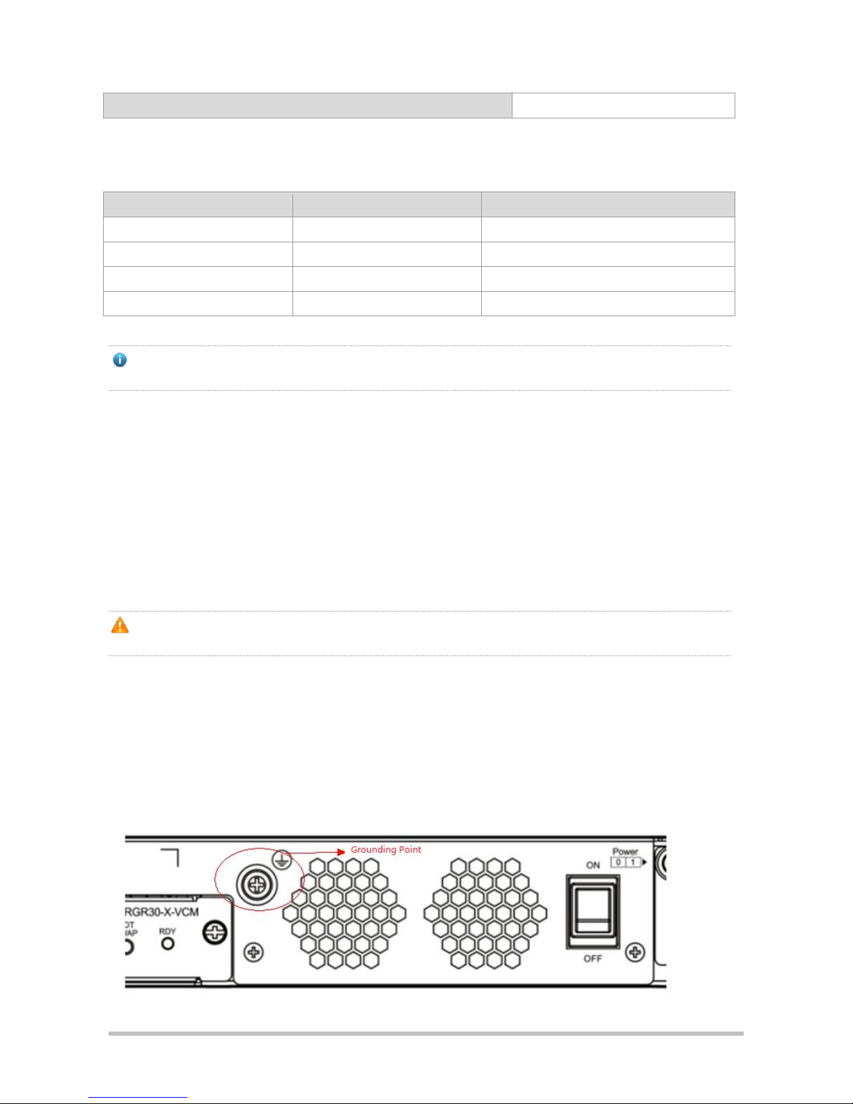
level reference. All the above constitute the comprehensive grounding requirements. The grounding resistance should
be less than 1Ω. One grounding point is reserved at the rear panel, as shown in the following figure.
Figure 2-1 Grounding Point of RSR30-X

·
2.2.6 Anti-interference Requirements
The router needs to be protected against electromagnetic and electrical interference. The requirements are as follows.
Effective measures should be taken for the power system to prevent the interference from the electric grid.
The working ground of the routers should be preferably separated and kept as far away as possible from the
grounding device of the power equipment or the anti-lightning grounding device.
Stay away from high frequency large current equipment like high-power radio-transmitting stations and radar
stations
Use electromagnetic shielding means when necessary.
2.2.7 Lightning Protection Requirements
Ruijie families of routers are designed with lightning protection. But as an electrical device, it may be damaged by
strong lightning strike. Therefore, you need do the following:
Ensure good contact between the grounding cable of the router and the ground.
Ensure good contact between the neutral point of the AC socket and the ground.
Consider adding a power supply arrester before the input front end of power supply to enhance lightning
protection.
2.2.8 Checking Installation Location
Whether the router is installed in a cabinet or placed on a workbench, make sure
There is enough room at the inlet wind gap and the vent of the router for heat dissipation of the cabinet.
Ruijie families of routers are equipped with fans. They draw in cold air from the radiating holes around the frame
and exhaust it from under the frame. Therefore, you need set aside at lease 10cm around the radiating holes. It is
recommended installing the router in a 19-inch standard cabinet. In the absence of a 19-inch standard cabinet,
place the router horizontally on a clean workbench. For hot climates, it is recommended using air-conditioning.
The cabinet or workbench is armed with good ventilating and cooling systems.
The cabinet or workbench is firm enough for supporting the router and its mount accessories.
The cabinet or workbench is well-grounded.
2.3 Installation Tools
Common Tools
Cross screwdriver, related electric and optical cables
Bolts, diagonal pliers, straps
Special Tools
Anti-static glove, stripping pliers, crimping pliers, crimping pliers for the crystal head,
wire cutter
Fiber Optic Cleaning Tools
Air-laid paper, optical fiber microscope
Meters
Multimeter, bit error rate tester (BERT), optical power meter
Relative Devices
Hub or switch
·
CSU/DSU or other DCE device
Configuration terminal, which may be a client or a PC with hyper terminal installed
Router modules
Power sockets
Some tools are customer supplied.
3 Router Installation
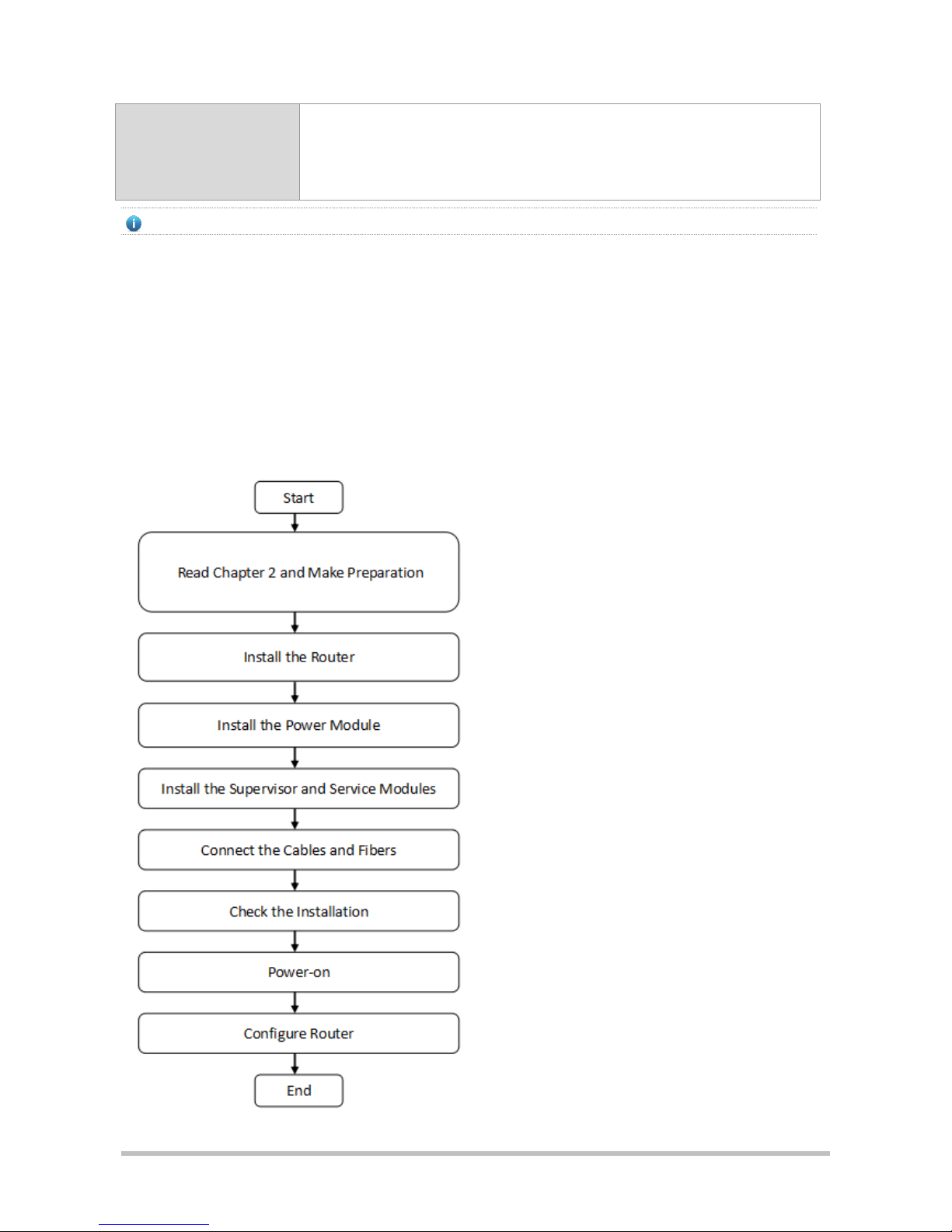
3.1 Procedure for Installing Router
Please follow the following procedure to install the router to ensure the smooth installation and avoid any damage to the
unit:

·
3.2 Mounting the Router
Now the router is ready for installation. Mount it to either of these two places.
A cabinet
A workbench
3.2.1 Mounting the Router to Cabinet
RSR30-X series routers is designed for 19-inch standard cabinets. Use the supplied fixing accessory for installation
when needed.
3.2.2 Mounting the Router to Workbench
In the absence of a 19-inch standard cabinet, install the router to a clean workbench. During the operation, make sure
that
The workbench is firm and well-grounded.
The supplied plastic cushion is stuck to the small hole at the bottom of the router and a room of 10cm is set aside
around the router for dissipation.
No weight is placed on the top of the router.
3.3 Installing Power Module
3.3.1 Installing Router Power Module
This part applies to the installation of the RSR30-X series routers. The module to be installed is the M5000E-AC60
power module.
1. Place the router in such a way that you face the rear panel of its host.
2. Remove the empty barrier on the slot where the power module is to be installed.
3. Flush the power module and the opening of the power module slot on the rear panel of the router host.
4. Drive the power module into the router host till it is in close contact with the back panel. Tighten the fastening
screw on the power module with a cross screwdriver.
Before installing the power module, make sure that the AC switch on it is switched off and the AC power cable is
disconnected with the AC power socket. Otherwise, electric shock or damage to the router may result.
In Step 3 be careful and drive the power module gently and smoothly. If you find the module hard to drive, never
drive it hard. Instead, remove the power module and check the power module is flush with the edge of the opening
of the rear panel. If it is, continue the operation. Otherwise the module may be damaged.

·
3.3.2 Removing Router Power Module
This part deals with the removal of the RSR30-X series routers. The module to be installed is the M5000E-AC60
power module.
1) Place the router in such a way that you face the rear panel of its host.
2) Switch off the power module to be removed and leave the switches of other power modules on.
3) Separate the fastening screw on the power module from the rear panel of the host by loosening it with a cross
screwdriver. Pull the power module out of the host and remove it from the host cabinet.
Before removing the power module, make sure that the AC switch on it is switched off and the AC power cable is
disconnected with the AC power socket. Otherwise, electric shock or damage to the router may result.
In Step 3 be careful and pull the power module out gently and smoothly. If you find the module hard to pull out,
never pull it hard. Instead check whether the power module is flush with the edge of the opening of the rear panel.
If it is, continue the operation. Otherwise the module may be damaged.
Install the empty power module slot with an empty barrier or power module.
The power supply socket should be installed near the device for convenient plugging.
3.4 Installing the Grounding Cable and the Power Cable
Ruijie RSR30-X series routers support the following AC power supply:
AC: 100–240 VAC; 50 Hz to 60 Hz; 2A
Verify that the power supply meets the requirement.
3.4.1 Installing the Grounding Cable
The router power cable is composed of three wires. You are recommended use a single-phase power socket with a
natural connector or a multifunctional PC power socket. The neutral point of the power supply should be reliably
grounded in the building. For common buildings, the neutral points have been buried into the ground during
construction and wiring. You must verify if the power supply of the building has been properly grounded.
3.4.2 Installing the Power Cable
The following table describes the procedure for installing the power cable:
1. Verify that the router switch is off. Connect one end of the supplied power cable to the socket on the rear panel of
the cabinet and the other end to the AC power socket.
2. Switch the router to power on position.
3. Verify that the PWR indicator on the front panel is on. If so, it indicates that the power cable is correctly connected.
3.4.3 Removing the Power Cable
The following table describes the procedure for removing the power cable:

·
1) Switch off the power supply module.
2) Unplug the power cord from the power slot in the power supply module.
3) Verify that the PWR indicator on the front panel is off.
3.5 Installing Power Cable and Grounding Cable
3.5.1 Installing Power Cable and Grounding Cable
Ruijie families of routers support this AC power supply.
AC: 100–240V 50/60Hz 2A
Make sure that your power supply meets the requirement.
The router uses three-wire power cable. It is recommended using single-phase three-wire power socket or
multi-functional microcomputer socket with neutral-point connector. The neutral-point needs to be grounded safely.
Check whether the power supply in your building is grounded correctly.
To install the power cable:
1) Check the router is in the power off position. Connect one end of the supplied power cable to the socket on the
rear panel of the cabinet and another to the AC power socket.
2) Turn the router to power on position.
3) Check the power indicator on the front panel is on. If it is, it means that the power cable is correctly connected.
3.5.2 Removing Power Cable and Grounding Cable
To remove the power cable:
1) Turn the router to power off position.
2) Unplug the end of the supplied power cable to the socket on the rear panel of the cabinet.
3) Check the power indicator on the front panel is off. If it is, it means that the power cable is correctly removed.
3.6 Installing DC Power Module
3.6.1 Installing the DC Power Module
Note: This section applies to the installation of the RSR30-X routers. The module to be installed is the PD240I DC
power module.
If the RSR30-X router uses the RG-RD240I DC power module, connect the DC power cables based on the marks and
location requirements on the panel of the RG-PD240I. See Figure 3-1.

·
Figure 3-1 PD240I Power Cable Installation
Blue wire
Brown wire
Yellow green wire
PGND
Power strip in the
equipment room
DC terminal block
in the chassis
Figure 3-2 PD240I Power Plug Installation
The installation procedures are as follows:
1. Take the DC power module PD240I and cables from the carton and insert the DC power module into the power
slot of the router.
2. Connect power cables to the DC terminal block in the chassis according to Figure a.

·
1) Connect the yellow green wire with the label of the power cable to the PGND in the power strip in the
equipment room.
2) Connect the brown wire with the "+" label of the power cable to the -48 VGND in the power strip in the
equipment room.
3) Connect the blue wire with the "-" label of the power cable to the -48 VDC in the power strip in the equipment
room.
3. Install the plug of the DC power cable to the PD240I according to Figure b.
1) Insert the power plug into the PD240I.
2) Check the wire color. The sequence should be yellow green, blue, and brown from left to right.
3) Fasten the two screws on the power plug.
A connection cable with brown, blue and yellow green wires is provided when the PD240I leaves the factory. On one
end, there is a three-core plug. You can directly insert it into the PD240I and fasten it. On the other end, there are three
wires with the "+", "-", and labels respectively and are connected to the DC power supply systems in the
equipment room.
Check whether the power cables are correctly installed before you power the device on.
Before installing the power module, ensure that the power switch is off.
3.6.2 Removing the DC Power Module
Note: This section applies to the removal of the RSR30-X routers. The module to be removed is the PD240I DC power
module.
Perform the following steps to remove power cables:
1. Turn the power switch of the router to the OFF position.
2. Loosen the screws on the plug and then pull the plug out of the PD240I according to Figure b in section 2.4.1.
3. Remove the DC power cable from the DC terminal block in the chassis.
Before removing the power module, ensure that the power switch is off.
3.7 Installation Check
When you have installed the router, before powering on it, do as follows:
If the router is stalled in a cabinet, check the installation brackets of the cabinet and router are firm. If the router is
stalled on the workbench, check there is enough room around the router for heat dissipation and the workbench is
firm.
Check the power supply meets the requirements.
Check the grounding cable is correctly connected.
Check the router is connected correctly to other devices like the configuration terminal.
·
3.8 Console Connection
The RSR30-X router provides a console port and a U-console port that comply with the EIA/TIA-232 asynchronous
serial standards.
You can perform the router configuration through either of the ports.
Specifications
Connector
RJ-45
Interface
standard
Asynchronous EIA/TIA-232
Baud rate
300-115,200bps, 9,600bps by defaut
Supported
services
1. Command line interface
2. Connection to character terminals
3. Providing terminal access service as an asynchronous interface
To connect the console port of the router:
1) Plug the supplied DB-9 or DB-25 connector to the serial port of the microcomputer or terminal on which the router
is to be configured. If you use a microcomputer, check it has a hyper terminal.
2) Connect one end of the supplied configuration cable to the console port of the router and another to the RJ45
interface with a DB-9 or DB-25 connector.
The console and U-console share the same port and either is available at a time. The 4-pin mini-B USB may be
easily confused with the 5-pin mini-B USB. Only the 5-pin mini-B connector can be used.
4 Router Startup and Configuration
4.1 Starting Router
4.1.1 Building Configuration Environment
When you use the router for the very first time, you will need to configure the router through a console port as follows:
1) As illustrated below, connect the serial port of a character terminal or microcomputer to the console port through a
RS232 cable.
a) Build a local configuration environment through the console port.
The console and AUX ports of the RSR30-X series routers are on the front of the router.
2) Set the communication parameters of the terminal. For a microcomputer, you will need to run a terminal emulation
program like Windows operating system’s Hyperterm. Take Hyperterm for example. Run Hyperterm, create a
connection, select the serial port to be connected with the router console, set communication parameters as
follows: baud rate to 9,600, data bit to 8, stop bit to 1, parity to No, flow control to No, and terminal emulation type
to VT100.

·
1. Create a connection.
2. Select the serial port to be connected with the router console.
3. Set communication parameters for the serial port.
4. Select a terminal emulation type.
When you have finished building the configuration environment, you may power on the router.
4.1.2 Powering on Router
4.1.2.1 Check before Powering on
Before powering on the router, please check
If the power cable and the grounding cable are connected correctly.
If the power supply voltage meets the requirement.
If the configuration cable is connected correctly, the microcomputer or terminal is turned on, and the setting is
complete.
Before powering on the router, check the position of the power switch so that you may cut power supply in time in
case of accident.
4.1.2.2 Powering on Router
Turn the router to the power on position.
4.1.2.3 Check after Powering on
After powering on the router, please check:
If the ventilating system is normal.
When the router is powered on, you will hear the fan working. Put your hand near the air vent hole, you will feel the
movement of air.
If the indicators on the front panel of the router are operating normally.
If the Power, Fan, and System indicators all light up green, it means everything is right. If one of them lights up red,
it indicates that there is a fault.
If the configuration terminal displays correctly.
When the router is powered on, information on router software self-decompression will appear on the terminal
display.
4.1.3 Starting Process
When the router is started for the first time, the following information appears:
***********************************************
dualboot crc verify:

·
#######################################################################################
#######################################################################################
################################################
Master boot is ok!
Press CTRL+T to do memory poweron-self-test!
System bootstrap(Master boot) ...
Boot Version: RGOS 10.4(3b23) Release(177348)
Nor Flash ID: 0x017E1000, SIZE: 8388608Bytes
Using 1500.000 MHz high precision timer.
CLOCK-3-HW_CAL_INVALID: Hardware Calendar (RTC) Error.
MTD_DRIVER-5-MTD_NAND_FOUND: 1 NAND chips(chip size : 536870912) detected
Press Ctrl+C to enter Boot .....
Verify the image .....[ok]
Loading main program ...
Loading main program 'rgos.bin'.
Load main program successfully.
Executing program, launch at: 0x04000000
CLOCK-3-HW_CAL_INVALID: Hardware Calendar (RTC) Error.
MTD_DRIVER-5-MTD_NAND_FOUND: 1 NAND chips(chip size : 536870912) detectedCopyright (c)
1998-2014s by Ruijie Networks.
All Rights Reserved.
Neither Decompiling Nor Reverse Engineering Shall Be Allowed.
*Jan 1 00:02:29: %SYS-5-COLDSTART: System coldstart.
MTD_DRIVER-5-MTD_NAND_FOUND: 1 nand chip(s) found on the target.
*Jan 1 00:45:53:%SYS-5-WARMSTART: System warmstart.
Ruijie>
Such information may vary with hardware configuration or software version.
Now the router is ready for configuration.
When using the router for the first time, it is recommended setting basic parameters using the configuration
function.
4.2 Configuring Router
Before using the router, you will have to configure it as needed. For more information on router configuration, see the
related Configuration Guide and Command Reference.

·
5 Troubleshooting
5.1 Troubleshooting Power Supply
For the RSR30-X series routers, you may use the power indicator on the front panel and the status indicator on the
power module to decide if the power supply system is operating normally. For description of indicators, see Chapter 1. If
a fault occurs, check
If the power supply meets the requirements.
If the router power switch is in the on position.
If the power supply switch of the router is in the on position.
If the power cable is connected correctly.
Never attempt hot swapping of the power cable. If the steps above did not solve your problem, contact your local
distributor or technical support personnel.
5.2 Troubleshooting Configuration System
When the router is powered on and everything is normal, information described in Chapter 4 during the start will appear
on the terminal. If a fault occurs, nothing or illegible characters will appear.
If no information appears on the terminal display, please check
If the power system is working normally.
If the console port cable is connected correctly.
If the steps above did not solve your problem, it is likely because of wrong configuration cable or wrong terminal
parameter setting. Please check terminal parameters.
If illegible characters appear on the terminal, this may be caused by mismatched terminal parameter setting. Check if
baud rate is set to 9600, data bit to 8, stop bit to 1, parity to No, flow control to No and terminal emulation type to VT100.
When the console port parameters of your router are modified, this may also lead to no display on the terminal.
6 Router Label Process
6.1 Label Handwriting
Tool: twin head permanent marker with one head marked Fine and the other head marked Ultra Fine. Please use the
Ultra Fine head of the marker when you write labels.

·
6.2 Label Pasting
Before pasting labels, write the content on the label paper, strip the label off, and then paste it to the cable or signboard
cable tie.
1. Position
A label is pasted 2 cm away from the plug by default and can be flexible adjusted, for example, the label should not be
pasted on the curved position or other positions that may affect the installation. The text on a label must be in the format
from left to right or from up to down, as shown in Figure 6-1. Details are as follows:
1. When the cable is vertically laid, the label should be in the format from left to right.
2. When the cable is horizontally laid, the label should be in the format from up down.
Figure 6-1 Left-right or up-down label text
2. Pasting Procedure
Figure 6-2 Label pasting
Paste side

·
6.3 Label Content
Label content
A pasted label has two sides, marking the locations of the two ports connected by the cable. Write the content based on
the onsite environment.
1. Write information about the local end in Area 1.
2. Write information about the peer end in Area 2.
3. Area 3 will be folded when you paste the label.
Figure 6-3 Label on the signal cable
Area
Area
Area
 Loading...