


RG-WLAN Series Access Point
Web-Based Configuration Guide, Release 11.1(5)B8

Copyright Statement
Ruijie Networks© 2016
Ruijie Networks reserves all copyrights of this document. Any reproduction, excerption, backup, modification,
transmission, translation or commercial use of this document or any portion of this document, in any form or by any means,
without the prior written consent of Ruijie Networks is prohibited.
, , , , ,
, , , ,
, , are registered trademarks of Ruijie Networks.
Counterfeit is strictly prohibited.
Exemption Statement
This document is provided “as is”. The contents of this document are subject to change without any notice. Please obtain
the latest information through the Ruijie Networks website. Ruijie Networks endeavors to ensure content accuracy and will
not shoulder any responsibility for losses and damages caused due to content omissions, inaccuracies or errors.

Preface
Thank you for using our products. This manual matches the RGOS Release 11.1(5)B8.
Audience
This manual is intended for:
Network engineers
Technical support and servicing engineers
Network administrators
Obtaining Technical Assistance
Ruijie Networks website: http://www.ruijienetworks.com/
Service Email: service_rj@ruijienetworks.com
Technical Support: http://www.ruijienetworks.com/service.aspx
Technical Support Hotline: +86-4008-111-000
Related Documents
Documents
Description
Command Reference
Describes the related configuration commands, including command modes,
parameter descriptions, usage guides, and related examples.
Hardware Installation and Reference
Guide
Describes the functional and physical features and provides the device
installation steps, hardware troubleshooting, module technical specifications,
and specifications and usage guidelines for cables and connectors.
Conventions
This manual uses the following conventions:
Convention
Description
boldface font
Commands, command options, and keywords are in boldface.
italic font
Arguments for which you supply values are in italics.

[ ]
Elements in square brackets are optional.
{ x | y | z }
Alternative keywords are grouped in braces and separated by vertical bars.
[ x | y | z ]
Optional alternative keywords are grouped in brackets and separated by
vertical bars.
Symbols
Means reader take note. Notes contain helpful suggestions or references.
Means reader be careful. In this situation, you might do something that could result in equipment damage or
loss of data.

Configuration Guide Web-based Configuration
Web-based Configuration
Overview
A user accesses the Web-based management system by using a browser (for example, IE browser) to manage the AP
device.
Web-based management involves two parts: Web server and Web client. A Web server is integrated onto a device to receive
and process requests sent from a client (for example, read a Web file or execute a command request) and returns the
processing result to the client. Generally, a Web client refers to a Web browser, for example, IE browser.
Currently, this file is applicable to only AP devices.
Application
Application
Description
Web-based Management
After finishing relevant configuration, a user can access the Web-based management
system through a browser.
Web-based Management
Scenario
As shown in the following figure, an administrator can access a device through a browser on a PC to manage the device.
Figure 1-1
Note
Web management system integrates configuration commands and sends them to the device through AJAX
request.
The device is enabled with the Web service to process the HTTP request to return the required data.
Function Deployment
Configuration Environment Requirements

Configuration Guide Web-based Configuration
Requirements for Client
An administrator logs in to the Web-based management system by using the Web browser on a client to manage the
device. Generally, a client refers to a PC. It may also be other mobile terminal devices, for example, a laptop.
Browser: IE7.0, IE8.0, IE9.0, IE10.0, IE11.0, Google chrome, Firefox, and some IE kernel-based browsers (for example,
Maxthon) are all supported. Exceptions such as messy code and format error may occur when other browsers are
used.
Resolution: It is recommended that the resolution be set to 1024 x 768, 1280 x 1024, or 1440 x 960. Exceptions such as
font alignment error and format error may occur when other resolutions are selected.
Requirements for server
The Web service must be enabled for the AP device.
Login authentication information for Web-based management must be configured for the AP device.
A management IP address must be configured for the AP device.
Default Configuration
The following table lists the default configuration of the Web management system.
Feature
Default Settings
Web service
Enabled
Management IP
192.168.110.1
Default Username/Password
Permission Description
admin/admin
Super administrator who possesses all permissions.
Login
You can type http://X.X.X.X (management IP address) in the address bar of a browser and press Enter to access the login
page, as shown in the following figure.
Figure 1-2 Login page

Configuration Guide Web-based Configuration
After typing the username and password, click Login.

Configuration Guide Web-based Configuration
Enter the username and password, click Login to access the Web management system.
Click Online Service for configuration help.
AP-Eweb Configuration
Quick Settings
Build a WiFi network for STAs to access and enjoy Internet services.

Configuration Guide Web-based Configuration
1) The Quick Settings page is displayed when you successfully logs in to the Web in the scenario that the device is in the
factory setting state, as shown in the preceding figure.
2) The Quick Settings page is also displayed when you click the Quick Settings link in the upper-right corner on the
homepage.
The device supporting NAT can work in AP access mode or wireless routing mode.

Configuration Guide Web-based Configuration

Configuration Guide Web-based Configuration
The device not supporting NAT can work only in AP access mode.

Configuration Guide Web-based Configuration
Configure the WiFi parameters, and click Finish to finish the configuration.
Favorites
System Homepage
The system homepage enables you to view the basic information of the AP device, including the device MAC address,
device model, system alarm information, flow trends of AP device ports, latest trends of all management APs, and STA
information corresponding to each management AP. In addition, it enables you to know the distribution condition of STA
signal strength in real time.

Configuration Guide Web-based Configuration
Click the Details link in the upper-right corner to view more system alarm information.
Click the Detail link in the upper-right corner of Top 10 Traffics or RSSI Distribution to view the STA information, for
example, the MAC address and RSSI.
User Information
STA information is displayed.
WiFi/WLAN
The WLAN allows wireless STAs to access the AP through WiFi to enjoy Internet services. You can add multiple WLANs.
You can also delete a WLAN.
The following figure shows the page for adding a WLAN.

Configuration Guide Web-based Configuration
Adding WiFi/WLAN
1) Click , a new panel for WiFi configuration is displayed.
2) Set the WiFi parameters.
3) Click Save to finish the configuration.
Editing the WLAN

Configuration Guide Web-based Configuration
1) Click the panel of WiFi you want to edit.
2) Edit the WiFi configuration.
3) Click Save. The Edit succeeded message is displayed.
Deleting WLANs
1) Click the panel of WiFi you want to delete.
2) Click Delete.
3) Click OK in the dialog box displayed to finish the deletion operation.
Wireless Channel Settings
Wireless channel settings are mainly about adjustment of the strength of the WiFi signal sent out by the device. You can set
channel parameters for the 2.4G and 5G networks.
Enabling the 2.4G network
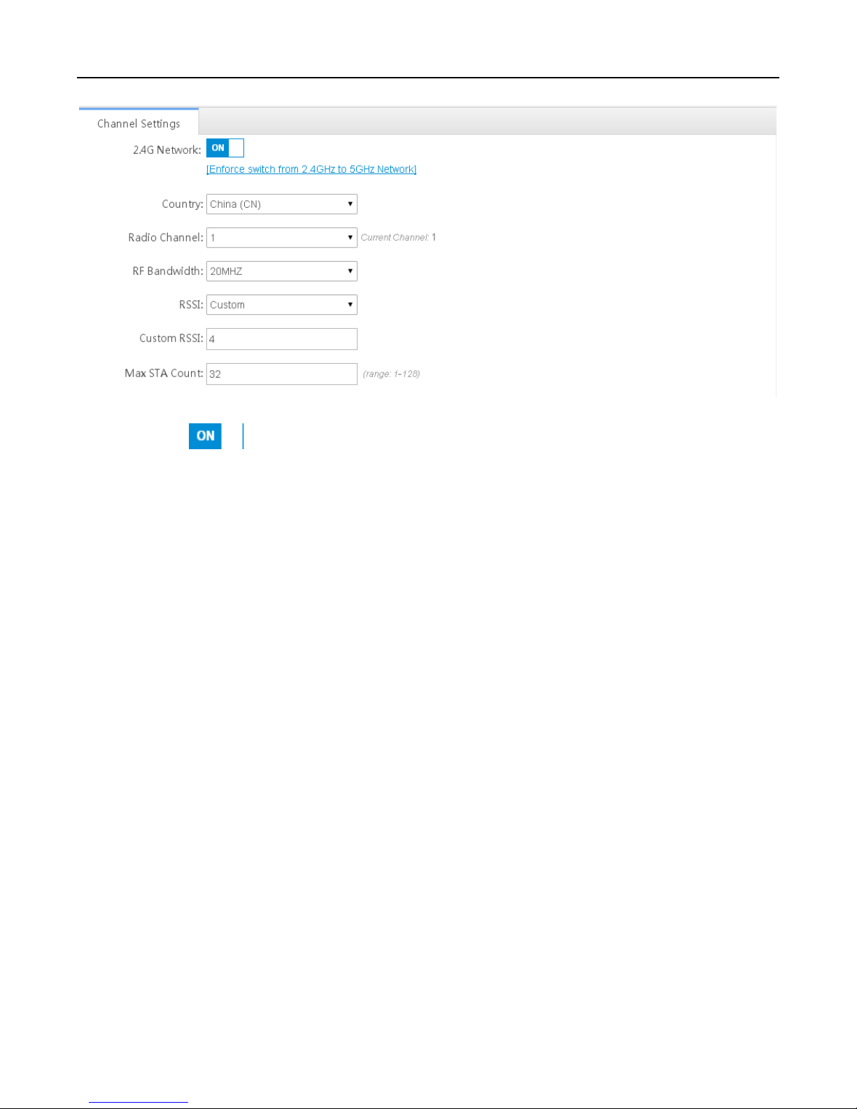
Configuration Guide Web-based Configuration
1) You can click to enable or disable the 2.4G network.
1) You can click Enforce switch from 2.4GHz to 5GHz Network to switch the network type forcibly.
Enabling the 5G network

Configuration Guide Web-based Configuration
1) You can click to enable or disable the 5G network.
2) You can click Enforce switch from 5GHz to 2.4GHz Network to switch the network type to 2.4G network forcibly.
Restart
You can restart the system by a click, which is convenient and efficient.

Configuration Guide Web-based Configuration
Click Restart to restart the device.
Network
External Network Settings
External network settings are mainly about configuration of the communication mode between the AP and external network.
Two communication modes are available, that is, AP access mode and routing mode.
The AP used by you might not support this function, which is subject to the actual menu items.
You can select the AP working mode to determine the AP role and then conduct configuration based on the corresponding
working mode.
Configuration Guide Web-based Configuration
Set corresponding parameters and save the configuration.
Wireless Bridging
Multiple APs are connected to each other in wireless repeater or bridging mode to achieve the purpose of connecting
distributed networks and spreading wireless signals. An AP device can be regarded as a repeater. It spreads the front-end
network and elongates the WiFi transmission distance for association and connection of STAs far away. Wireless bridging
supports the 2.4G network and 5G network bridging.
Enable the 2.4G or 5G network bridging function as required, select the Central Base Station operating mode, and click
Save to finish configuration.
Advanced
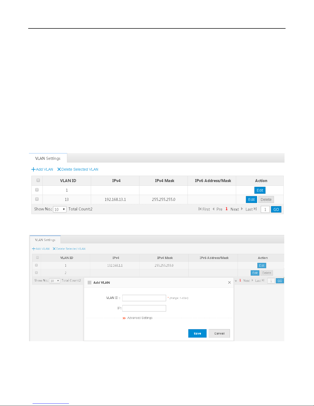
VLAN
Adding a VLAN
Click Add VLAN. A dialog box is displayed, as shown in the preceding figure. Set corresponding parameters in the dialog
box and click Save. The newly added VLAN is displayed in the VLAN list after the Add succeeded message is displayed.
Configuration Guide Web-based Configuration
Deleting VLANs in batches
1) Select the VLAN to be deleted from the list.
2) Click Delete Selected VLAN to finish the deletion operation.
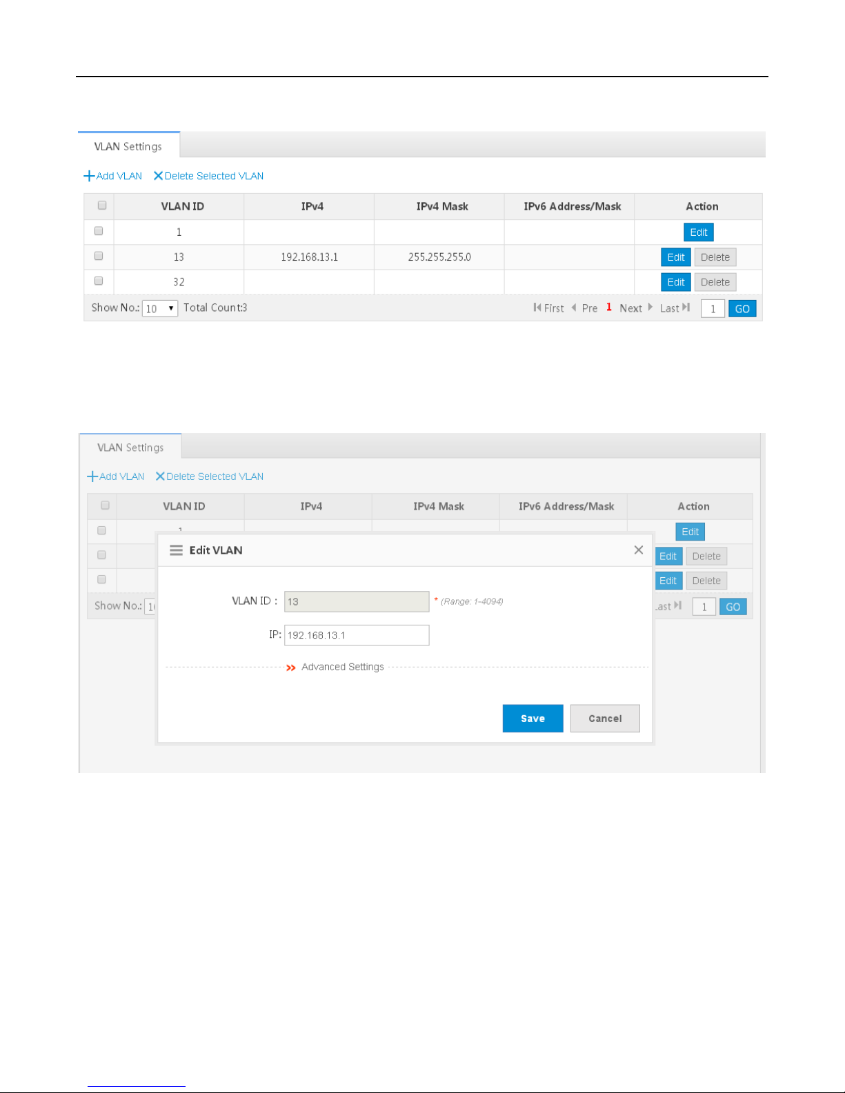
Editing a VLAN
Click the Edit button. A dialog box is displayed, as shown in the preceding figure. Click Save. The Save succeeded
message is displayed.
Deleting a VLAN
Configuration Guide Web-based Configuration
Click the Delete button for a VLAN in the list and then click OK in the dialog box displayed to finish the deletion operation.
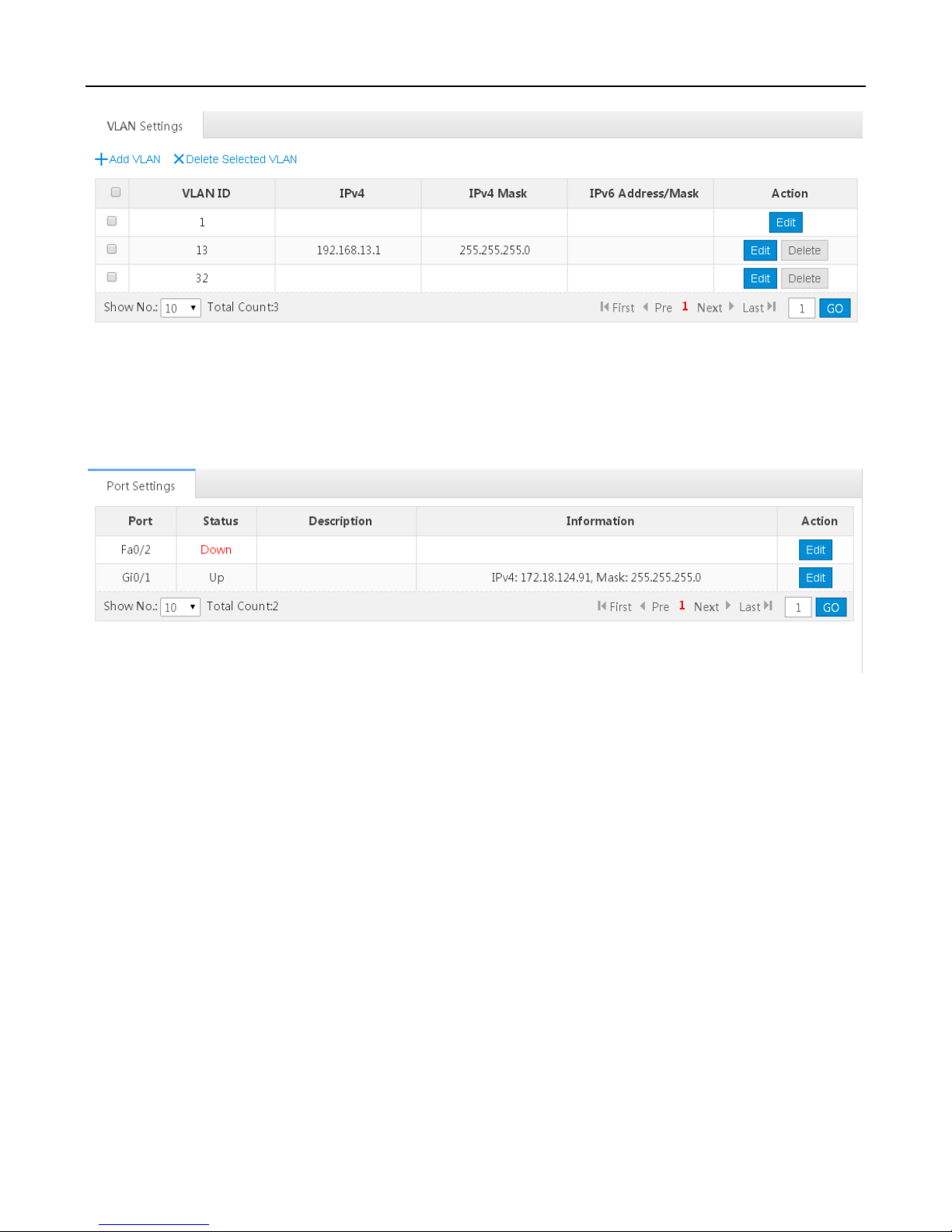
Port
Port Settings
Editing port settings
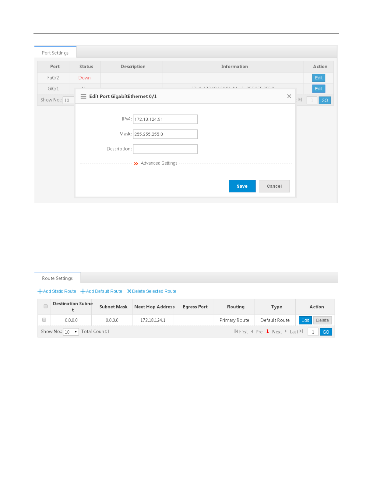
Configuration Guide Web-based Configuration
1) Click the Edit button for a port in the list.
2) The configuration about the port is displayed in the dialog box. Then edit the configuration.
3) Click Save. The Save succeeded message is displayed.
Route
Adding a static route
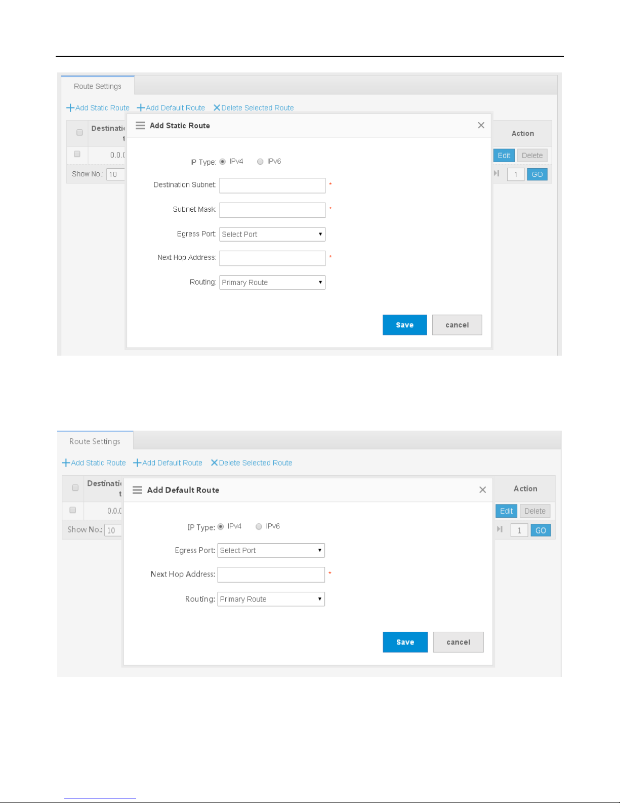
Configuration Guide Web-based Configuration
Click Add Static Route, set the configuration items in the dialog box displayed, and click Save. The newly added static route
is displayed in the route list after the Save succeeded message is displayed.
Adding the default route
Click Add Default Route, set the configuration items in the dialog box displayed, and click Save. The newly added route is
displayed in the route list after the Save succeeded message is displayed.
Configuration Guide Web-based Configuration
Deleting routes in batches
1) Select the route from the list.
2) Click Delete Selected Route to finish the deletion operation.
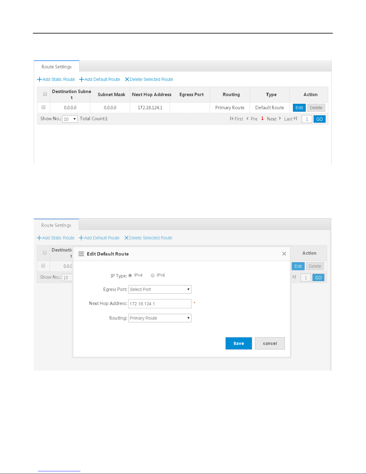
Editing a route
1) Click the Edit button for a route in the list.
2) A dialog box is displayed, as shown in the preceding figure. The configuration about the route is displayed. Then edit
the configuration.
3) Click Save. The Save succeeded message is displayed.
Configuration Guide Web-based Configuration
Deleting a route
Click the Delete button for a route in the list and then click OK in the dialog box displayed to finish the deletion operation.
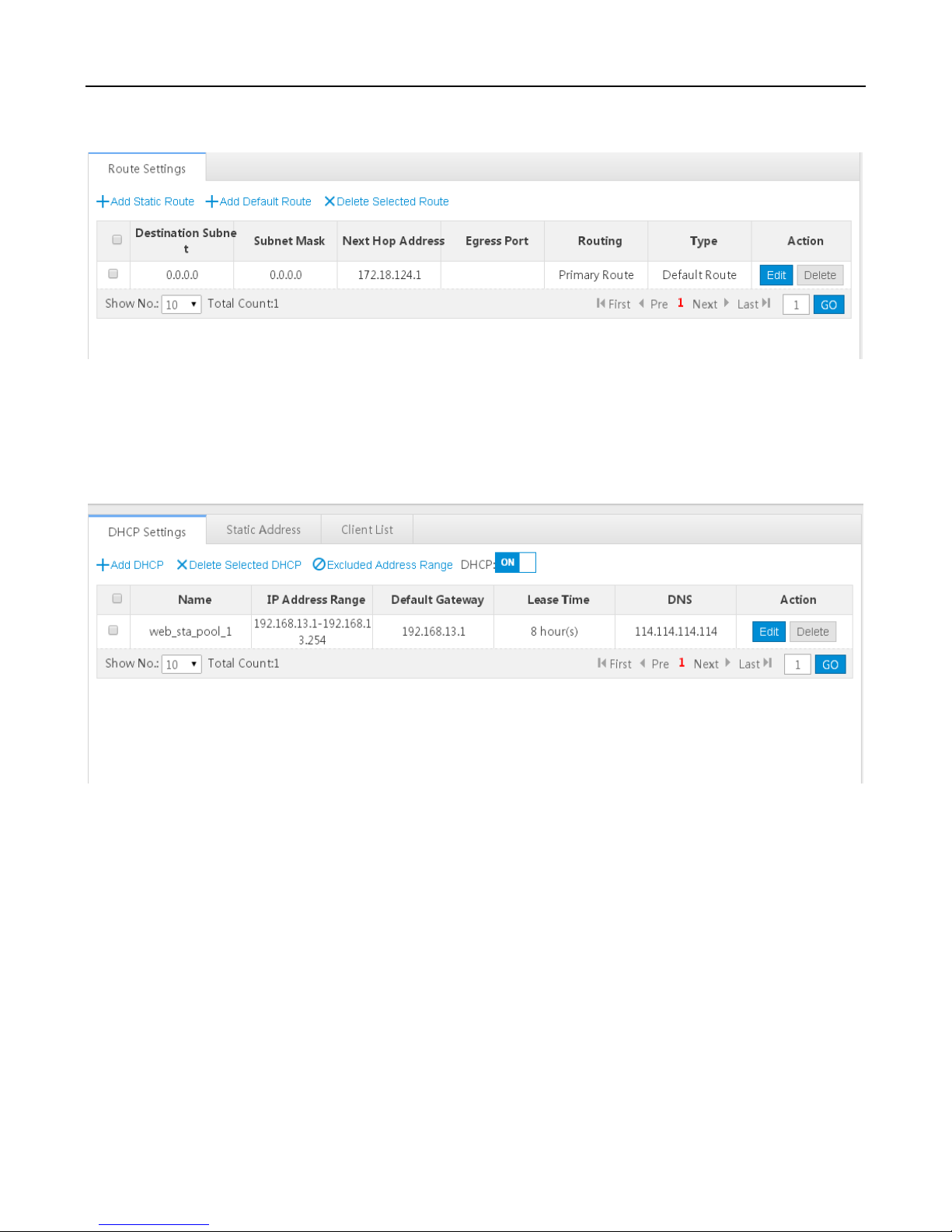
DHCP
DHCP Settings
Adding a DHCP Pool

Configuration Guide Web-based Configuration
Click Add DHCP, set the configuration items in the dialog box displayed, and click Save. The newly added DHCP pool is
displayed in the DHCP pool list after the Save succeeded message is displayed.
Deleting DHCPs in batches
1) Select the DHCP pool from the list.
2) Click Delete Selected DHCP and then click OK in the dialog box displayed to finish the deletion operation.
Configuring excluded address range

Configuration Guide Web-based Configuration
Click Excluded Address Range. A dialog box is displayed, as shown in the preceding figure. Set the configuration items in
the dialog box displayed, and click Save. The newly configured address range is displayed in the DHCP pool list after the
Save succeeded message is displayed.
DHCP service

Configuration Guide Web-based Configuration
You can click to enable or disable the DHCP service.
Editing a DHCP pool
1) Click the Edit button for a DHCP pool in the list.
2) The configuration about the DHCP pool is displayed in the dialog box. Then edit the configuration.
3) Click Save. The Save succeeded message is displayed.
Deleting a DHCP pool

Configuration Guide Web-based Configuration
Click Delete to finish the deletion operation.
Static Address
Adding a static address

Configuration Guide Web-based Configuration
Click Add Static Address, set the configuration items in the dialog box displayed, and then click Save. The newly added
static address is displayed in the list after the Save succeeded message is displayed.
Deleting static addresses in batches
1) Select the static address from the list.
2) Click Delete Selected Address and then click OK in the dialog box displayed to finish the deletion operation.
Editing a static address
1) Click the Edit button for a static address in the list. A dialog box is displayed.
2) The configuration about the static address is displayed in the dialog box. Then edit the configuration.
3) Click Save. The Save succeeded message is displayed.

Configuration Guide Web-based Configuration
Deleting a static address
Click the Delete button for a static address in the list to finish the deletion operation.
Client List
Binding a MAC address to a dynamic IP address
1) Select the static address from the list.
2) Click Bind MAC to Dynamic IP and then click OK in the dialog box displayed to finish the deletion operation.
Querying client based on the IP address
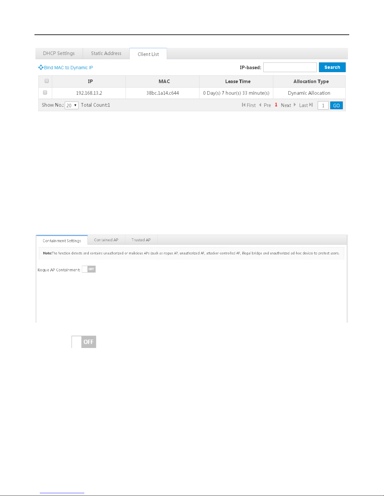
Configuration Guide Web-based Configuration
Input the IP address in the text box. Click Search. The search results meeting the criterion are displayed in the list.
Containment
Rogue APs may exist in a WLAN. Rogue APs may have security vulnerabilities and they may be manipulated by attackers.
Therefore, rogue APs seriously threaten and endanger network security. The containment function can be enabled on the AP
to attack rogue devices and prevent other wireless STAs from being associated with rogue devices.
Containment Settings
You can click to enable or disable the rogue AP containment for the device.
Contained AP
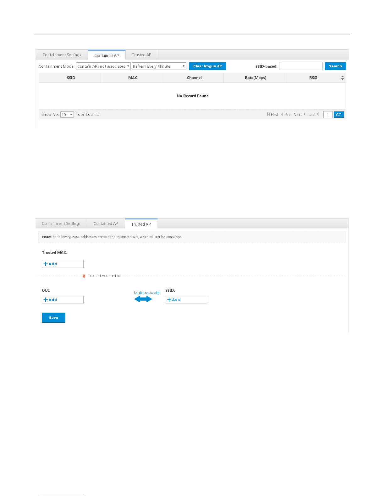
Configuration Guide Web-based Configuration
You can select the containment mode and view the WiFi list corresponding to the contained rogue APs.
You can click Clear Rogue AP to clear all contained APs.
Trusted AP
When the rogue AP containment function is enabled for the AP, the APs not authorized will be contained. However, some
APs are trusted devices and therefore special processing is required. You can configure the MAC addresses of trusted
devices.
Blacklist/Whitelist
To increase the wireless security, you can control the access of wireless users by allowing or not allowing some users to
access the WiFi.

Configuration Guide Web-based Configuration
Click the icon to a blacklist or whitelist.
Add the icon to delete the selected whitelist or blacklist.
Click the icon to bulk import whitelists or blacklists.
You can click the SSID-based Access Control link to configure the blacklist and whitelist for each WiFi.
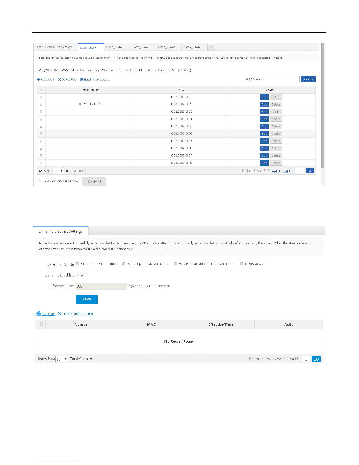
Configuration Guide Web-based Configuration
Dynamic Blacklist
Add malicious attack sources to the dynamic blacklist to prohibit access.
Configuration Guide Web-based Configuration
1) Set the parameters and then save the configuration.
2) Select the blacklist from the list.
3) Click Delete Selected Item and then click OK in the dialog box displayed to finish the deletion operation.
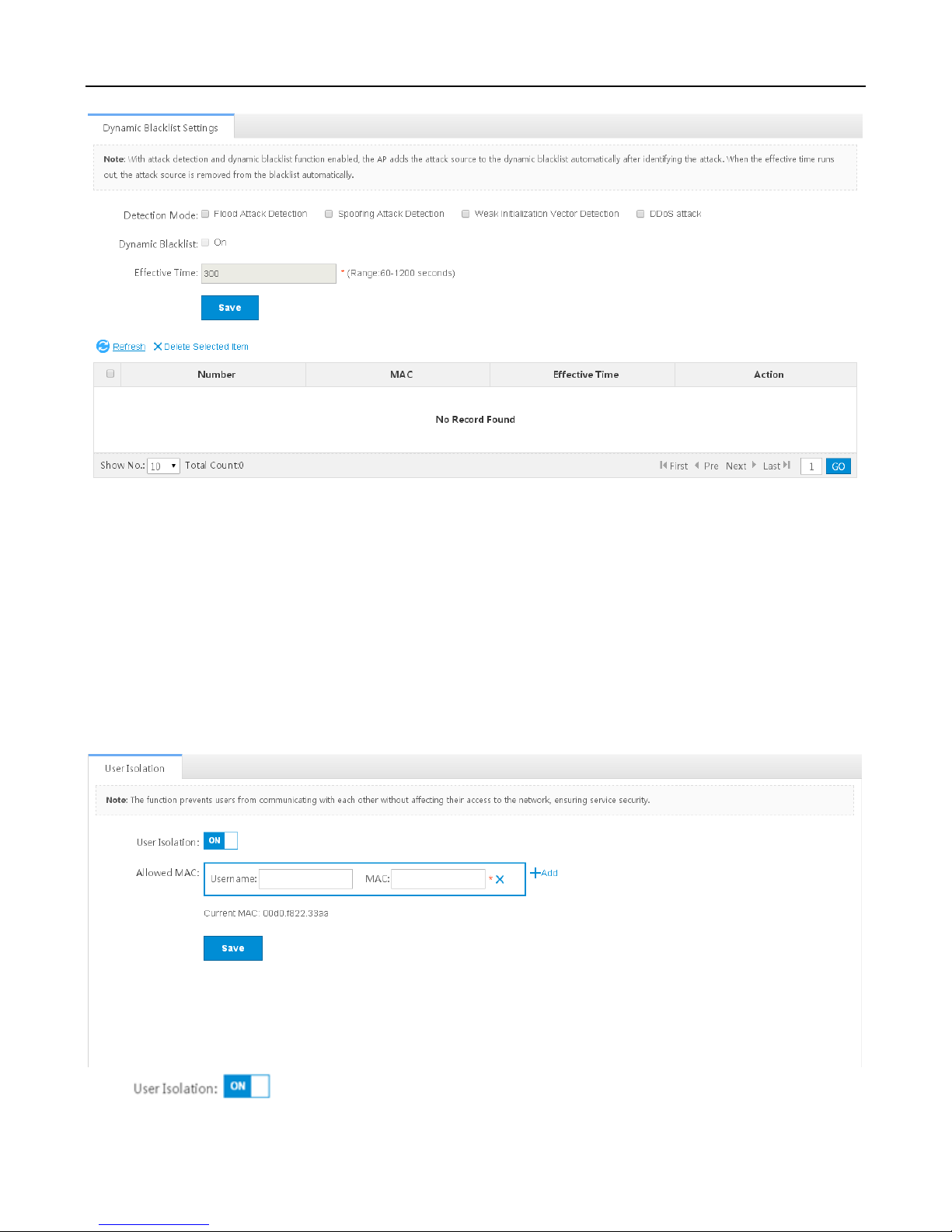
Prohibiting Mutual Access of Internal and External Networks
To ensure network security and prevent unwitting information transfer, you can prohibit communication between internal
network users by means of configuration. Some special users (users who can access each other) can be identified based on
the user name and MAC address.
Click to enable or disable mutual access of internal network users.
Configuration Guide Web-based Configuration
Click to delete the MAC address of the user.
Click the Add icon to add a MAC address for a mutual-access user. You can add multiple MAC addresses.
Click Save to finish the configuration.
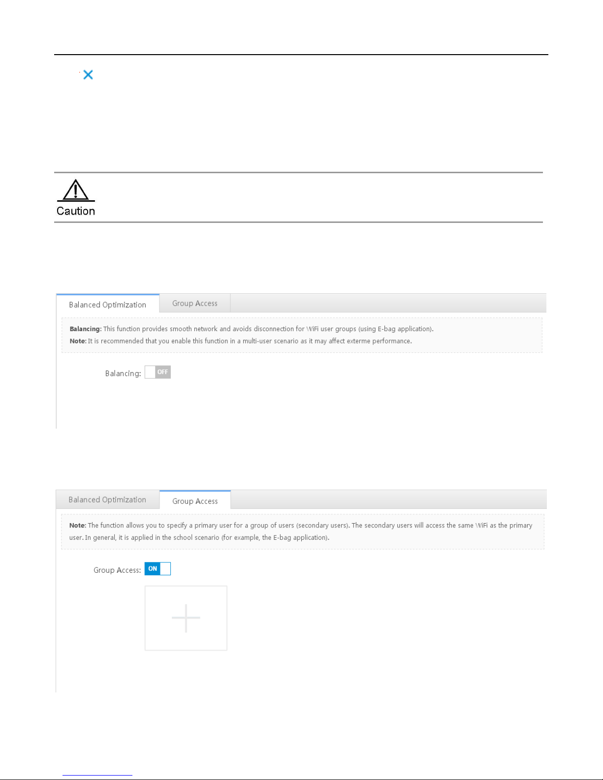
E-bag Optimization
The AP used by you might not support this function, which is subject to the actual menu items.
This function is mainly applicable to the E-bag solution for a school. Balanced optimization ensures smooth network and
avoids disconnection when a user uses the E-bag application.
Balanced Optimization
It is recommended that you enable this function in a multi-user scenario as it may affect performance.
Group Access
Configuration Guide Web-based Configuration
Click the button to enable or disable the Group Access function.
Configure the user binding relationship. Configure bound primary user and secondary user data.
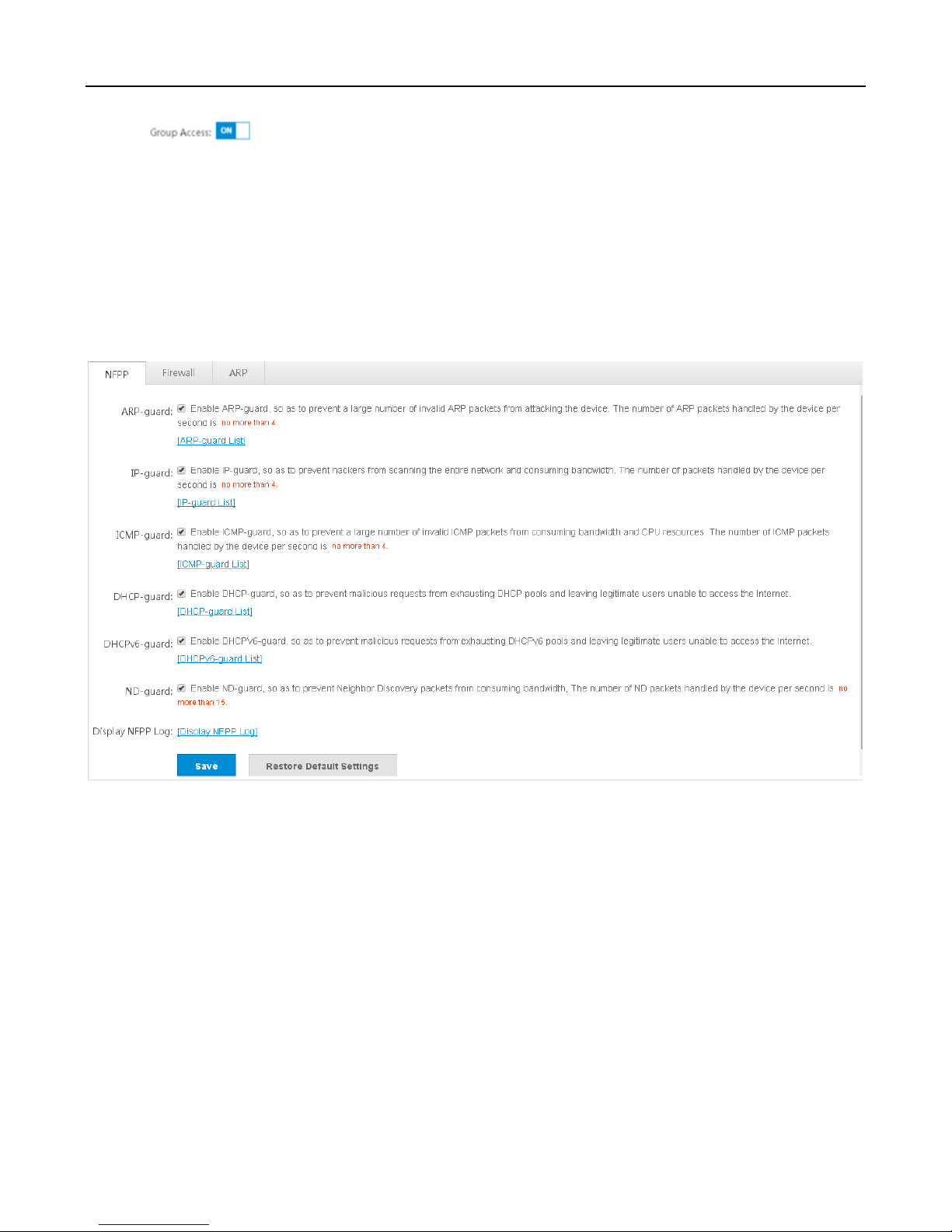
Anti-attack/ARP Table
Some malicious attacks are always found in the network environment. These attacks may bring about extremely heavy
burden for the switch, resulting in excessive CPU usage of the switch and giving rise to an operation failure of the switch.
NFPP
ARP-guard: Enables ARP-guard configuration. Click the ARP-guard List link to view the host where ARP attack is detected.
IP-guard: Enables IP-guard configuration. Click the IP-guard List link to view the host where IP scanning is detected.
ICMP-guard: Enables ICMP-guard configuration. Click the ICMP-guard List link to view the host where ICMP attack is
detected.
DHCP-guard: Enables DHCP-guard configuration. Click the DHCP-guard List link to view the host where DHCPv4 attack is
detected.
DHCPv6-guard: Enables DHCPv6-guard configuration. Click the DHCPv6-guard List link to view the host where DHCPv6
attack is detected.
ND-guard: Enables ND-guard configuration.
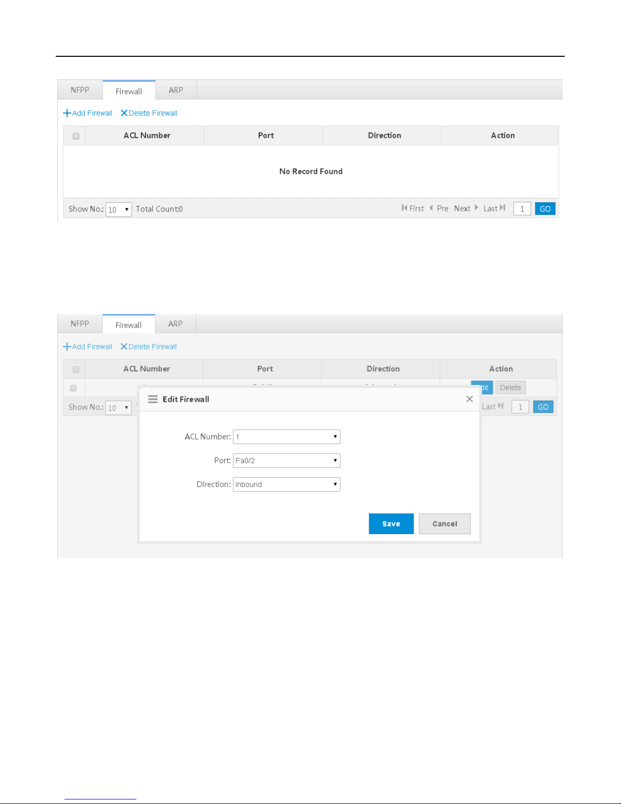
Firewall

Configuration Guide Web-based Configuration
Adding firewall
1) Click Add Firewall.
2) The Add Firewall dialog box is displayed. Set the configuration items.
3) Click Save. The newly added firewall is displayed in the firewall list after the Save succeeded message is displayed.
Deleting firewalls in batches
Configuration Guide Web-based Configuration
1) Select one or multiple records from the firewall list.
2) Click Delete Firewall and then click OK in the dialog box displayed to finish the deletion operation.
Editing firewall
1) Click the Edit button for a certain firewall in the list.
2) The configuration about the firewall group is displayed in the dialog box. Then edit the configuration.
3) Click Save. The Save succeeded message is displayed.
Deleting firewall

Configuration Guide Web-based Configuration
Click the Delete link for a certain firewall in the firewall list and click OK in the dialog box displayed to finish the deletion
operation.
ARP
Dynamic Binding>>Static Binding

Configuration Guide Web-based Configuration
1) Select one or multiple records from the ARP list.
2) Click the Dynamic Binding>>Static Binding icon to switch from dynamic binding to static binding in batches.
Remove static Binding
1) Select one or multiple records from the ARP list.

Configuration Guide Web-based Configuration
2) Click the Remove static Binding icon to remove static binding in batches.
Manual Binding
1) Click the Manual Binding icon.
2) Set the IP address and MAC address.
3) Click OK. The newly bound ARP is displayed in the ARP list after the Save succeeded message is displayed.
ACL List
When receiving a packet on a port, the input ACL checks whether the packet matches the ACE entry for this port. When the
device intends to output a packet through a port, the output ACL checks whether the packet matches the ACE entry for this
port.
When there are different filtration rules, multiple rules may be applied simultaneously and only several of them may be
applied. If a packet matches an ACE entry, this packet is processed (permit or deny) according to the action policy defined by
this ACE.

Configuration Guide Web-based Configuration
ACL List
Adding an ACL
Click Add ACL and set the configuration items in the dialog box displayed. Click OK. The newly added ACL is displayed in
the ACL List drop-down list on the left after the Save succeeded message is displayed.
Deleting an ACL

Configuration Guide Web-based Configuration
1) Select the ACL from the ACL List drop-down list.
2) Click Delete ACL to finish the deletion operation.
Adding an access rule
1) Click Add Access Rule.
2) Set the configuration items in the dialog box displayed.
3) Click OK. The newly added access rule is displayed in the access rule list after the Save succeeded message is
displayed.
Editing an access rule

Configuration Guide Web-based Configuration
1) Click the Edit button for an access rule in the access rule list.
2) The configuration about the access rule is displayed in the dialog box. Then edit the configuration.
3) Click OK. The Save succeeded message is displayed.
Deleting an access rule
1) Select one or multiple records from the access rule list.
2) Click Delete Selected Access Rule and then click OK in the dialog box displayed to finish the deletion operation.
ACL Time
You can enable ACLs based on time, for example, make ACLs take effect in some time segments of a week. To meet this
requirement, you must configure a time object first.

Configuration Guide Web-based Configuration
Adding a time object
Click Add Time Object, set the configuration items in the dialog box displayed, and then click Save. The newly added time
object is displayed in the time object list after the Save succeeded message is displayed.
Deleting time objects in batches

Configuration Guide Web-based Configuration
1) Select one or multiple records from the time object list.
2) Click Delete Selected Time Object and then click OK in the dialog box displayed to finish the deletion operation.
Editing a time object
1) Click the Edit button for a time object in the list.
2) The configuration about the time object is displayed in the dialog box. Then edit the configuration.
3) Click Save. The Save succeeded message is displayed.
Deleting a time object
Click the Delete button for a time object in the list.
Configuration Guide Web-based Configuration
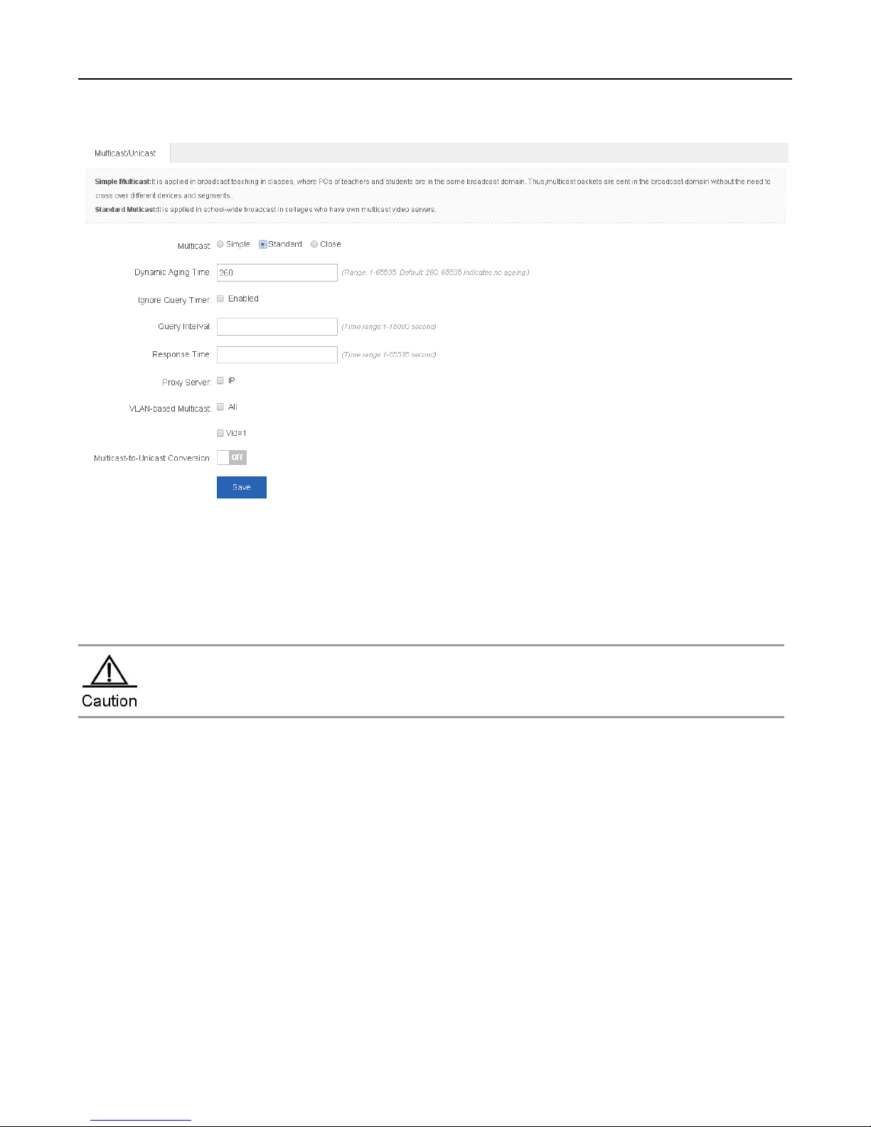
Unicast/Multicast
Set parameters as required, and then click Save.
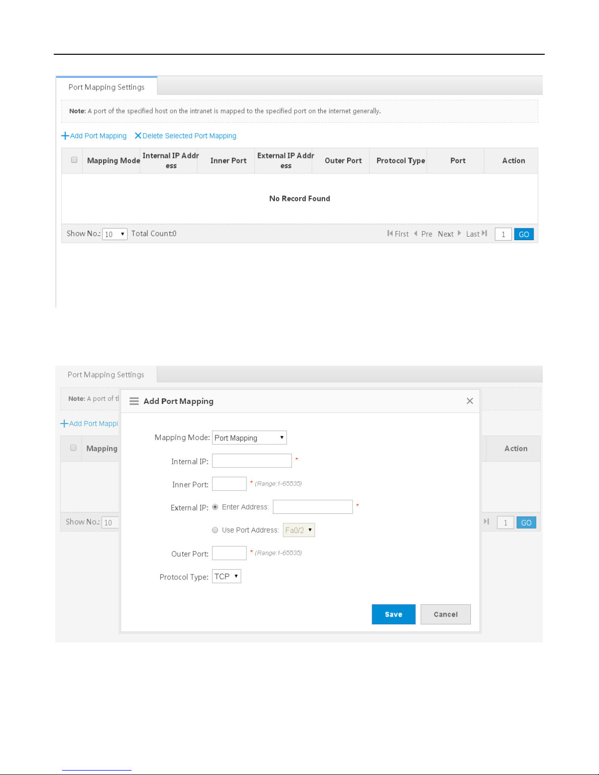
Port Mapping
Generally, this function is used to map a specified port of a specified host in the internal network to a specified port of an
external network address.
The AP used by you might not support this function, which is subject to the actual menu items.
Configuration Guide Web-based Configuration
Adding port mapping
Click Add Port Mapping, set the configuration items in the dialog box displayed, and then click Save. The newly added port
mapping is displayed in the list after the Save succeeded message is displayed.
Configuration Guide Web-based Configuration
Deleting port mapping in batches
1) Select the port mapping from the list.
2) Click Delete Selected Port Mapping and then click OK in the dialog box displayed to finish the deletion operation.
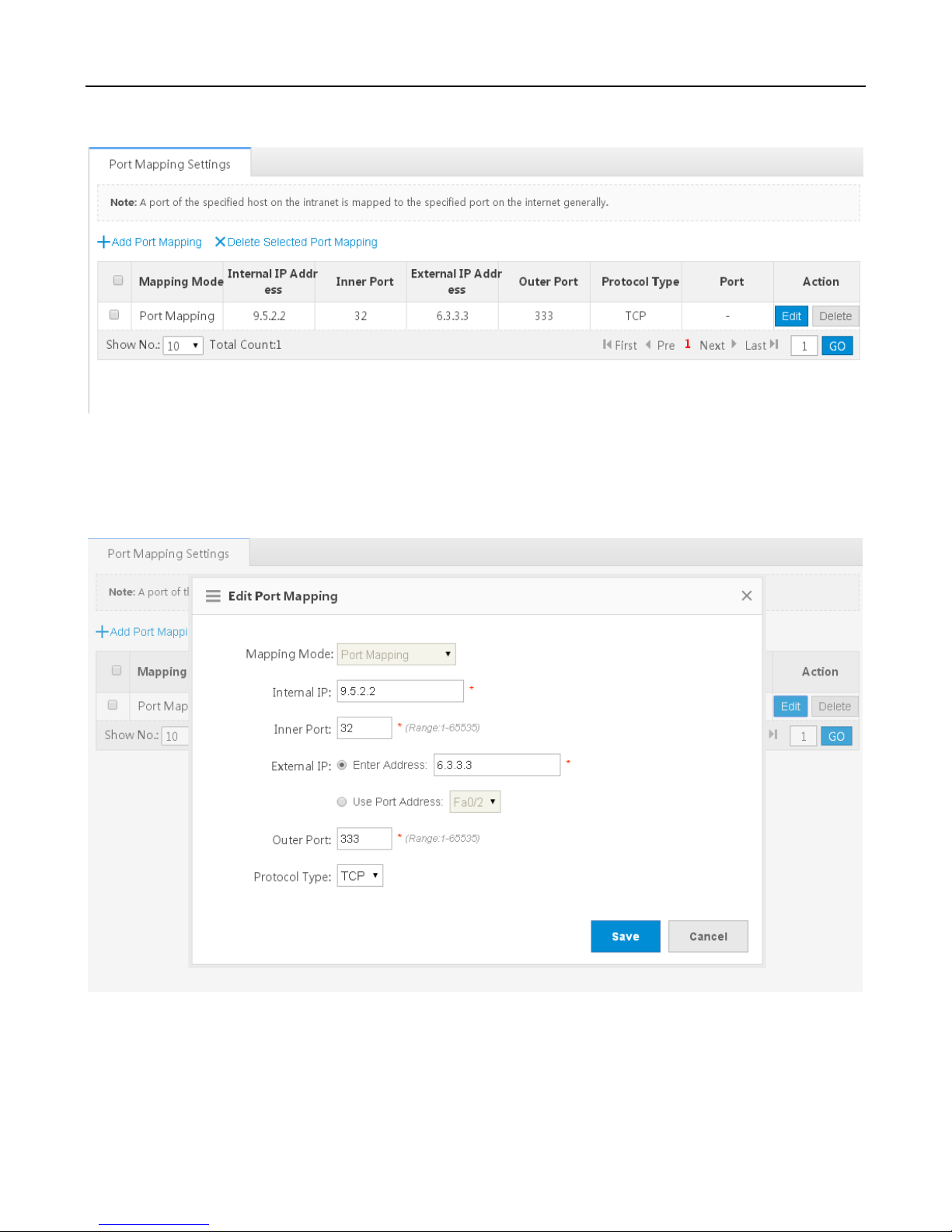
Editing port mapping
1) Click the Edit button for a port mapping in the list.
2) The configuration about the port mapping is displayed in the dialog box. Then edit the configuration.
3) Click Save. The Save succeeded message is displayed.
Configuration Guide Web-based Configuration
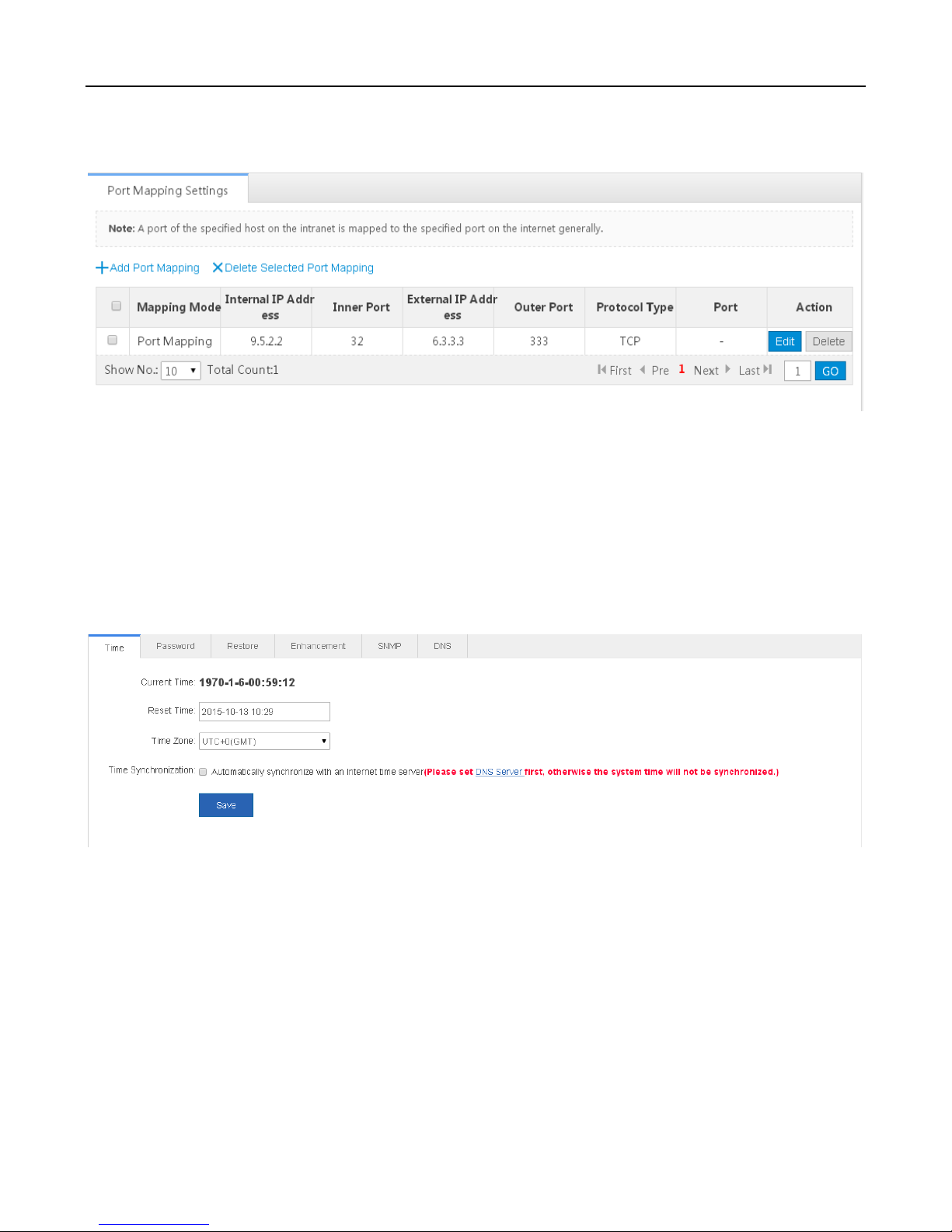
Deleting port mapping
Click the Delete button for a port mapping in the list to finish the deletion operation.
System
System Settings
Time
Set the system time based on the region of the device.
Password
To improve the information exchange security, please change the default password of the system.

Configuration Guide Web-based Configuration
Restore
Restore configurations to the factory settings. The configuration can be imported and exported in batches, facilitating user
operation.
Configuration Guide Web-based Configuration
After selecting a configuration file, you can click Import to import this configuration file.
You can click Export Current Configuration to download the latest configuration file.
You can click Restore Factory Settings to clear the configurations and restore to the initial state.
You can click the Display Current Configuration button to view the configurations in the box below this button.
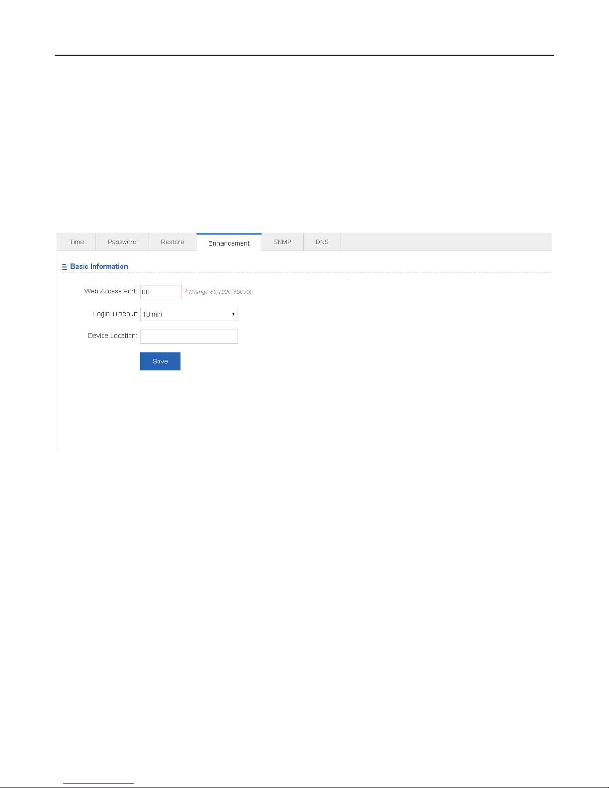
Enhancement
To facilitate device management, set Device Location for better device examination. After Login Timeout is set, the Web
system logs out automatically when you leave for a long time, ensuring system security.
SNMP
SNMP provides a method of collecting network management information from the network devices. It can help to manage
network devices.

Configuration Guide Web-based Configuration
Set the configuration items, and click Save.
DNS
Dynamic domain name resolution (DNS) can be enabled only after the DNS server is configured.
Configuration Guide Web-based Configuration
Click to add a DNS server.
Click to delete a DNS server.
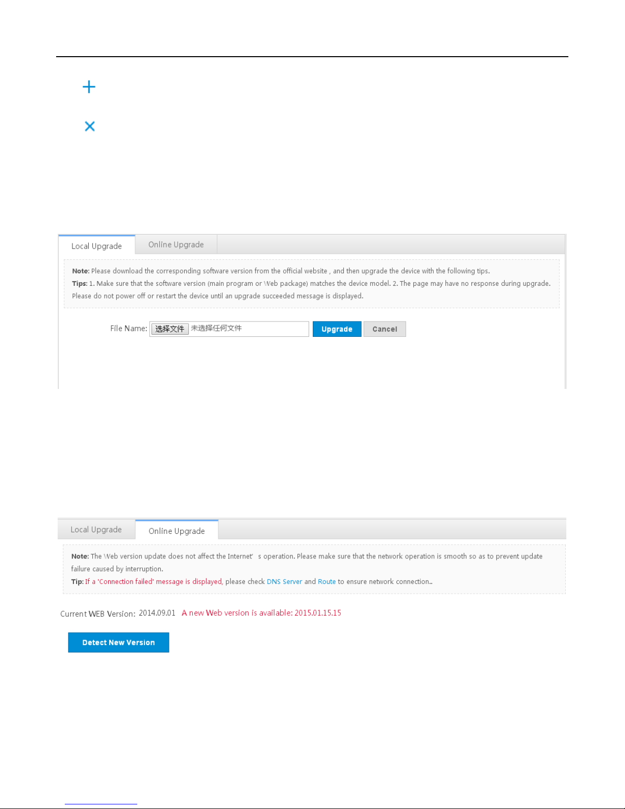
Upgrade
Local Upgrade
Download the main program or Web package to the local device and perform local upgrade.
Click to select the main program or Web package to be upgraded.
You can click Cancel to terminate an ongoing upgrade.
Online Upgrade
Online upgrade needs no Web package download. When the device can access the Internet, you can upgrade the Web
package in online mode.
You can click the DNS Server and Route links to check network connection.

Configuration Guide Web-based Configuration
Permission
A system may have multiple users of different levels that correspond to different permissions. You can set or view
permissions through the Permission Settings page. The system has two default users: user admin
Adding an administrator
Click Add Administrator. A dialog box is displayed, as shown in the preceding figure. Set the configuration items in the
dialog box, and click Save. The newly added administrator is displayed in the list after the Save succeeded message is
displayed.
Editing administrator information

Configuration Guide Web-based Configuration
1) Click the Edit button for an administrator in the list.
2) A dialog box is displayed, as shown in the preceding figure. The configuration about the administrator is displayed in the
dialog box. Then edit the configuration.
3) Click Save. The Save succeeded message is displayed.
Deleting an administrator
You can click Delete to delete an administrator.
Logging
Local logs on the device are sent to a corresponding server for storage, facilitating access to these logs.
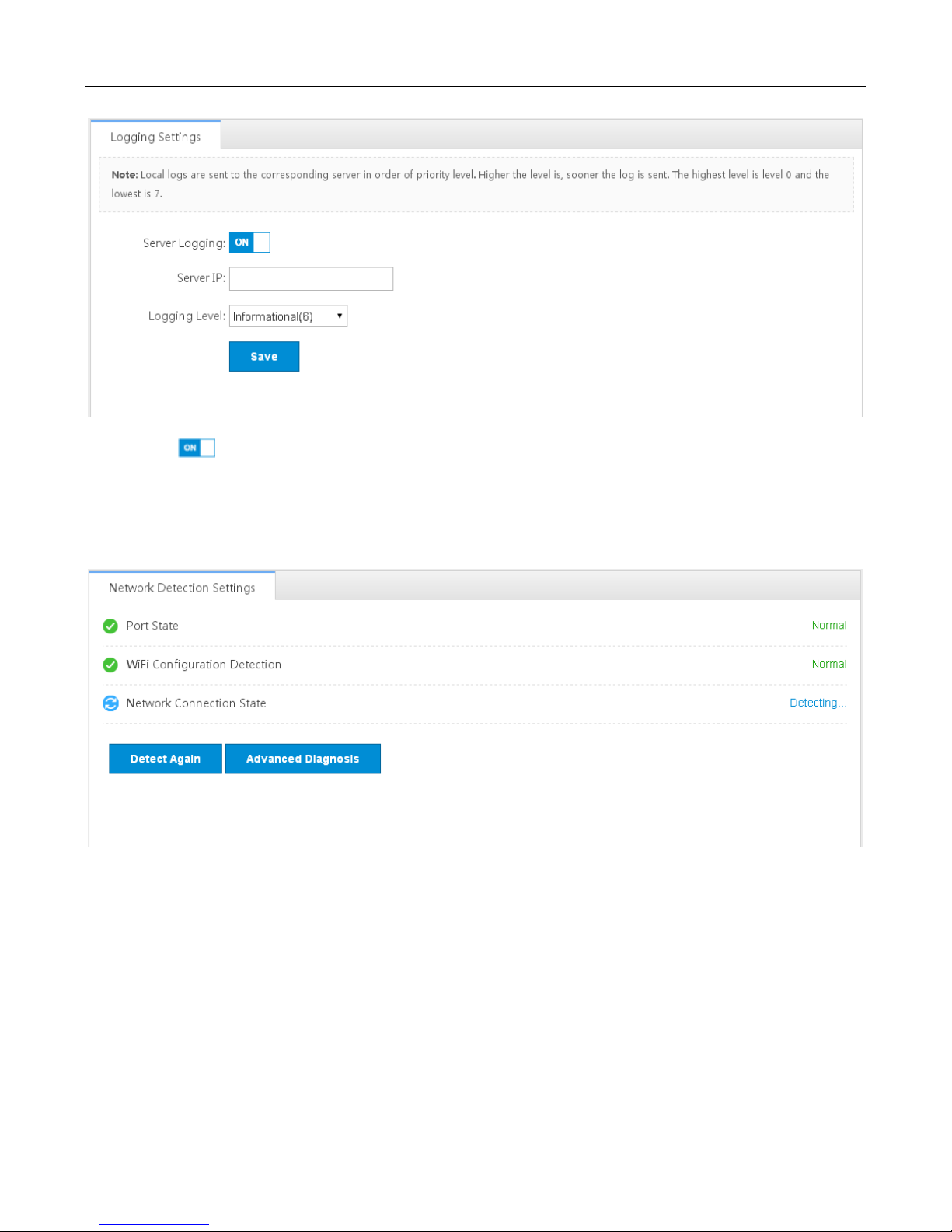
Configuration Guide Web-based Configuration
You can click to enable or disable the logging function of the server.
Detection
When the network is faulty, you can detect network connections for troubleshooting.
When the AP are faulty, click the Route link to view and configure relevant information.
Click the Advanced Diagnosis button to detect network connection.
Web Console

Configuration Guide Web-based Configuration
You can configure any command on Web Console as in the Telnet operation. But you cannot log in to an AP using Telnet or
entering any command in Shell mode.
Fat/Fit Switch
Select the AP mode.

Configuration Guide Web-based Configuration
Enabling the Web Server
The Web service is enabled for an AP device when this AP is delivered. By default, the IP address is 192.168.110.1. The
following describes how to enable Web service on the CLI when it is disabled.
Configuration
Commands
Configuring the Web
server
enable service web-server
Enables the Web service.
ip address
(Optional) Configures the IP address.
webmaster level username password
(Optional) Configures the username and
password for logging in to the Web-based
management system.
Configuration Method
Enabling the Web Service
Mandatory configuration.
This configuration is performed on the AP device.
Configuring the IP Address
Optional configuration.
Configuring the Username and Password for Logging In to the Web-Based Management System
Optional configuration.
When the Web service is enabled, the administrator username/password (admin/admin) and guest user/password
(guest/guest) are created by default. The passwords of these two accounts can be changed. In addition, you can create
other Web-based management accounts.
Verification
You can log in to the Web page by using the preset IP address and Web-based management account and password, and
check whether the login is successful.
Relevant Commands
Enabling the Web Service
Command
enable service web-server [ http | https | all ]
Parameter
Description
http | https | all: Enables corresponding services. http enables the HTTP service, https enables the
HTTPS service, and all enables both the HTTP and HTTPS services. By default, both the HTTP and HTTPS
services are enabled.
Command
Mode
Global configuration mode.
Configuring the IP Address

Configuration Guide Web-based Configuration
Command
ip address ip-address ip-mask
Parameter
Description
ip-address: IP address.
ip-mask: network mask.
Command
Mode
Interface configuration mode.
Configuring the Account and Password for Logging In to the Web-Based Management System
Command
webmaster level privilege-level username name password { password | [ 0 | 7 ] encrypted-passw
Parameter
Description
privilege-level: indicates the level of the permission bound to the user. Three levels are available, which are
0, 1, and 2. The super administrator account (admin) created by default corresponds to level 0, a guest
account (guest) corresponds to level 2, and other accounts correspond to level 1.
name: address of the static RP.
password: The ACL is used to limit the group address range of the static RP service. The default range is all
group services.
0 | 7: password encryption type. 0 indicates no encryption, and 7 indicates simple encryption. The default
value is 0.
encrypted-password: password.
Command
Mode
Global configuration mode.
Usage Guide
N/A
Configuration Example
Configuring the Web Server
Configuration
Steps
Enable the Web service.
Configure the local username and password.
Configure the device management IP address. The default management VLAN is VLAN 1.
Configure an IP address for VLAN 1. Ensure that the management IP address can be pinged from the user’s
PC.
Ruijie# configure terminal
Ruijie(config)# enable service web-server
Ruijie(config)# webmaster level 0 username admin password admin
Ruijie(config)#interface vlan 1
Ruijie(config-if-VLAN 1)#ip address 192.168.1.200 255.255.255.0
Ruijie(config)# end
Verification
Run the show running-config command to display related configuration commands.
Ruijie(config)#show running-config
Building configuration...
Current configuration : 6312 bytes
!

Configuration Guide Web-based Configuration
hostname ruijie
!
!
webmaster level 0 username admin password 7 08022b181b29
webmaster level 1 username manager password 7 06073f
webmaster level 2 username guest password 7 14155f083206
http update mode auto-detect
!
!
interface VLAN 1
ip address 192.168.1.200 255.255.255.0
no shutdown
!
line con 0
line vty 0 4
login
!
!
End
Web-based Configuration Examples
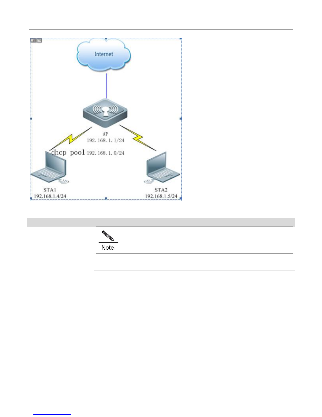
Constructing a WLAN for the DHCP Server on the AP Device
The AP is regarded as a wireless router and constructs a small-scale network as a fat AP. The DHCP server is configured on
the AP device. The following figure shows the topology.
Figure 1-1 Topology 1 (AP is in routing mode)
Configuration Guide Web-based Configuration
Configuration
Description and Command
Construction of a WLAN for
the DHCP server on the AP
Mandatory. It is used to configure a WLAN.
WiFi name
Associates wireless signal for Internet
access of an STA
WiFi password
A STA inputs the password for Internet
access.
DHCP configuration
Allocates IP addresses to wireless STAs.
Verification
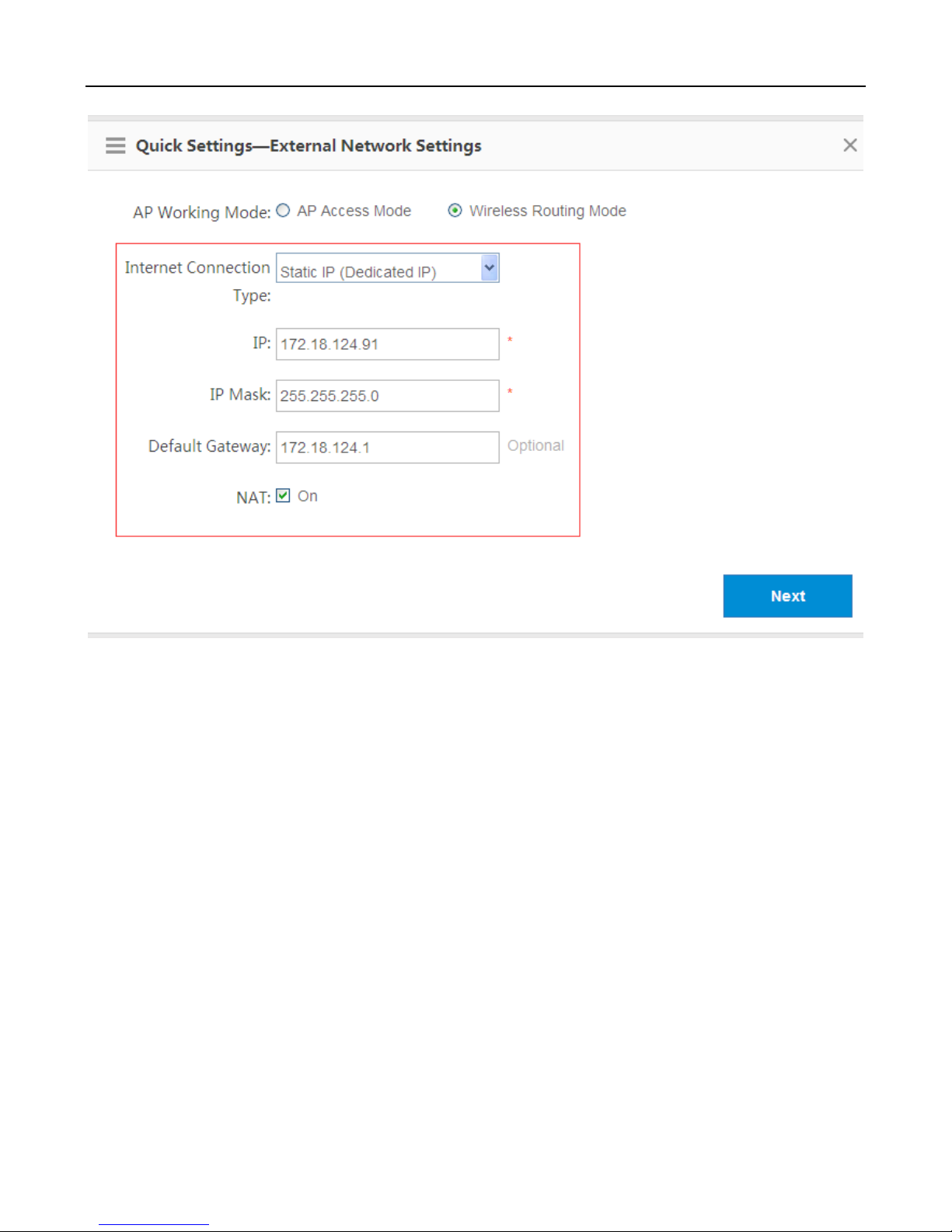
1) Select AP working mode and set the Internet connection type
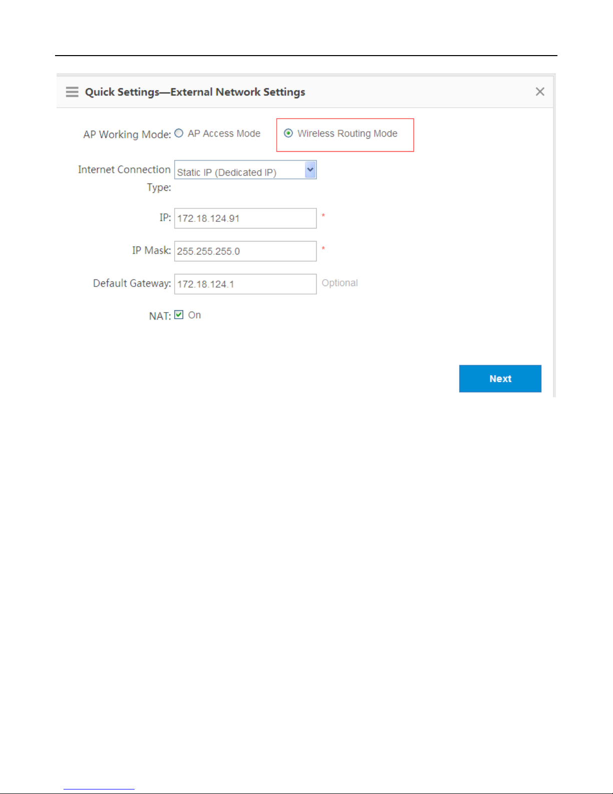
Configuration Guide Web-based Configuration
The AP works in wireless routing mode.
You can select the following Internet connection types when the AP works in wireless routing mode.
Static IP (dedicated IP)
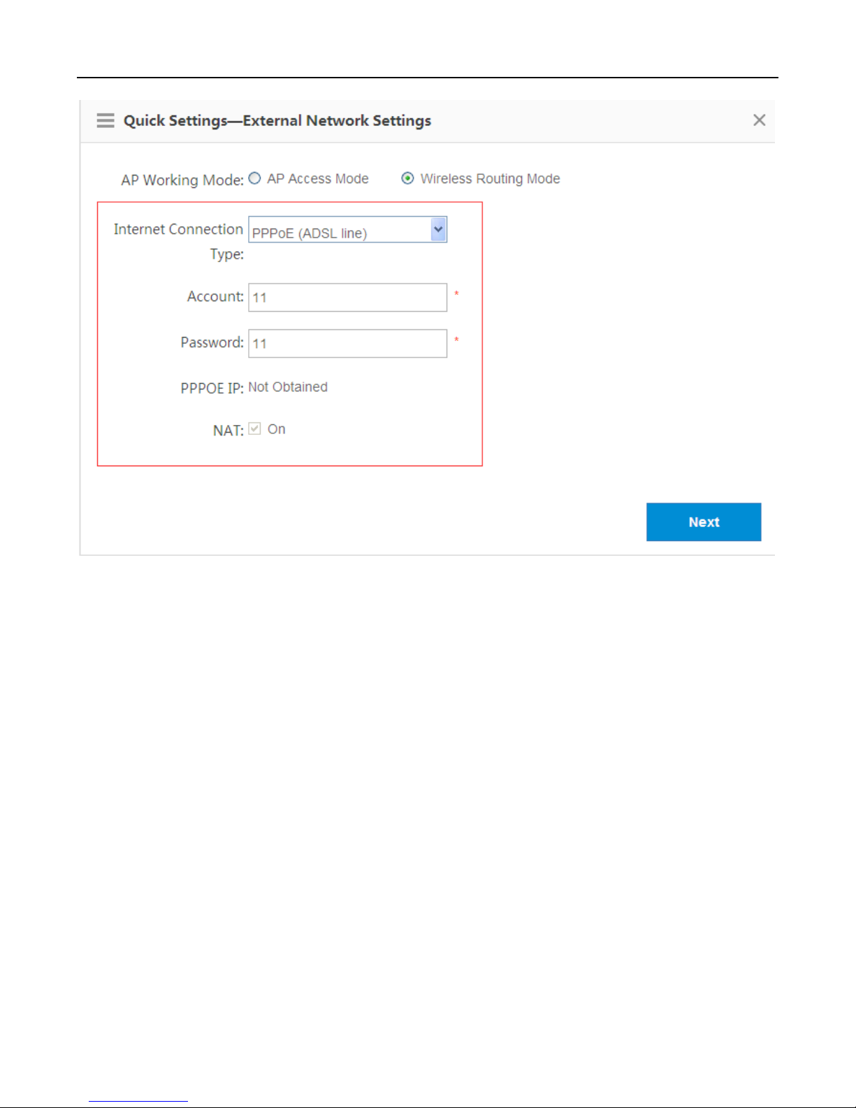
Configuration Guide Web-based Configuration
PPPoE (ADSL line)
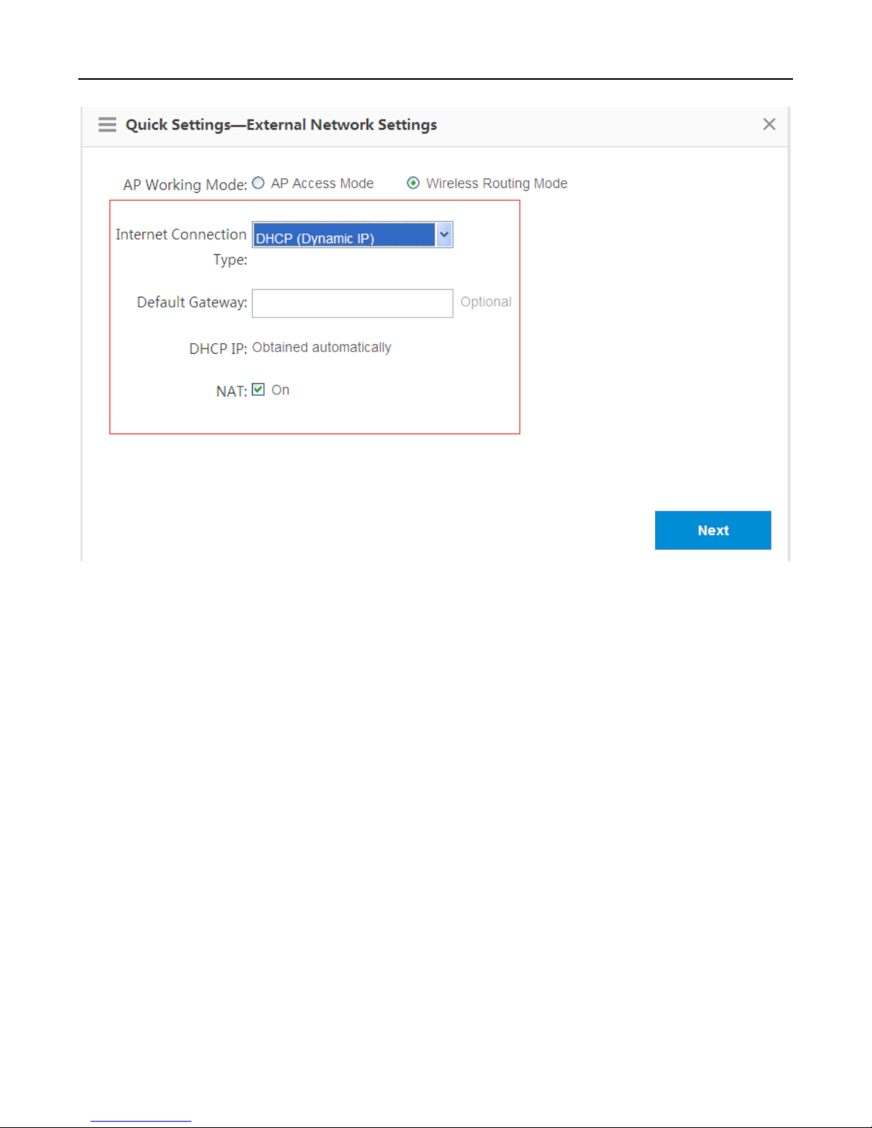
Configuration Guide Web-based Configuration
DHCP (dynamic IP)
Configuration Guide Web-based Configuration
Configuration Guide Web-based Configuration
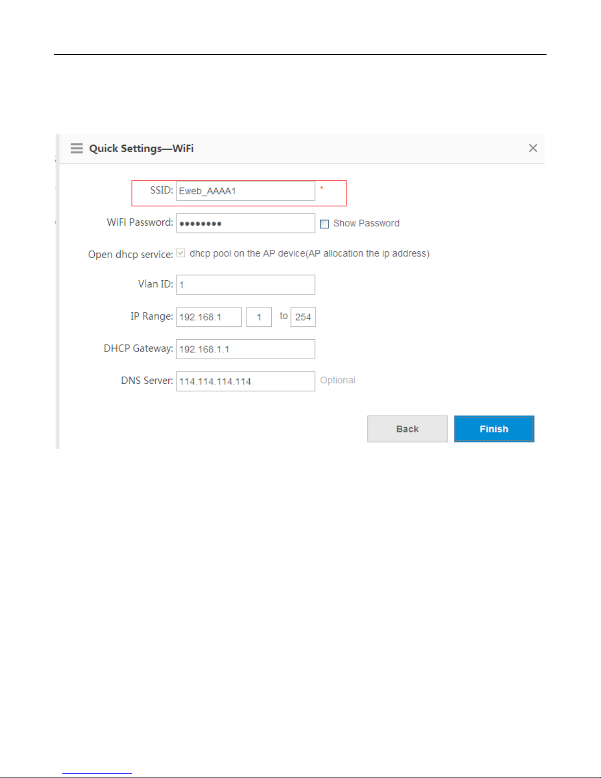
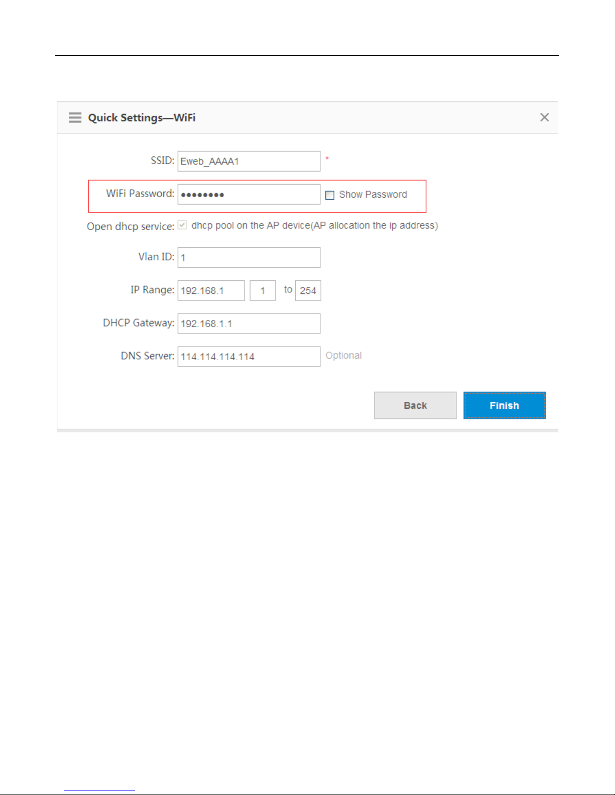
Configure a WiFi name (you can configure a simple name that is easy to remember, for example, zhangsan). A
WiFi name contains up to 32 characters.
Figure 1-3 AP Quick Settings for SSID
2) Security configuration
By default, the WPA2-PSK mode is selected. A password consists of 8 to 64 characters, and it can be a combination of
letters, digits, and some special characters.
Configuration Guide Web-based Configuration
Figure 1-4 AP Quick Settings for Security
Configuration Guide Web-based Configuration
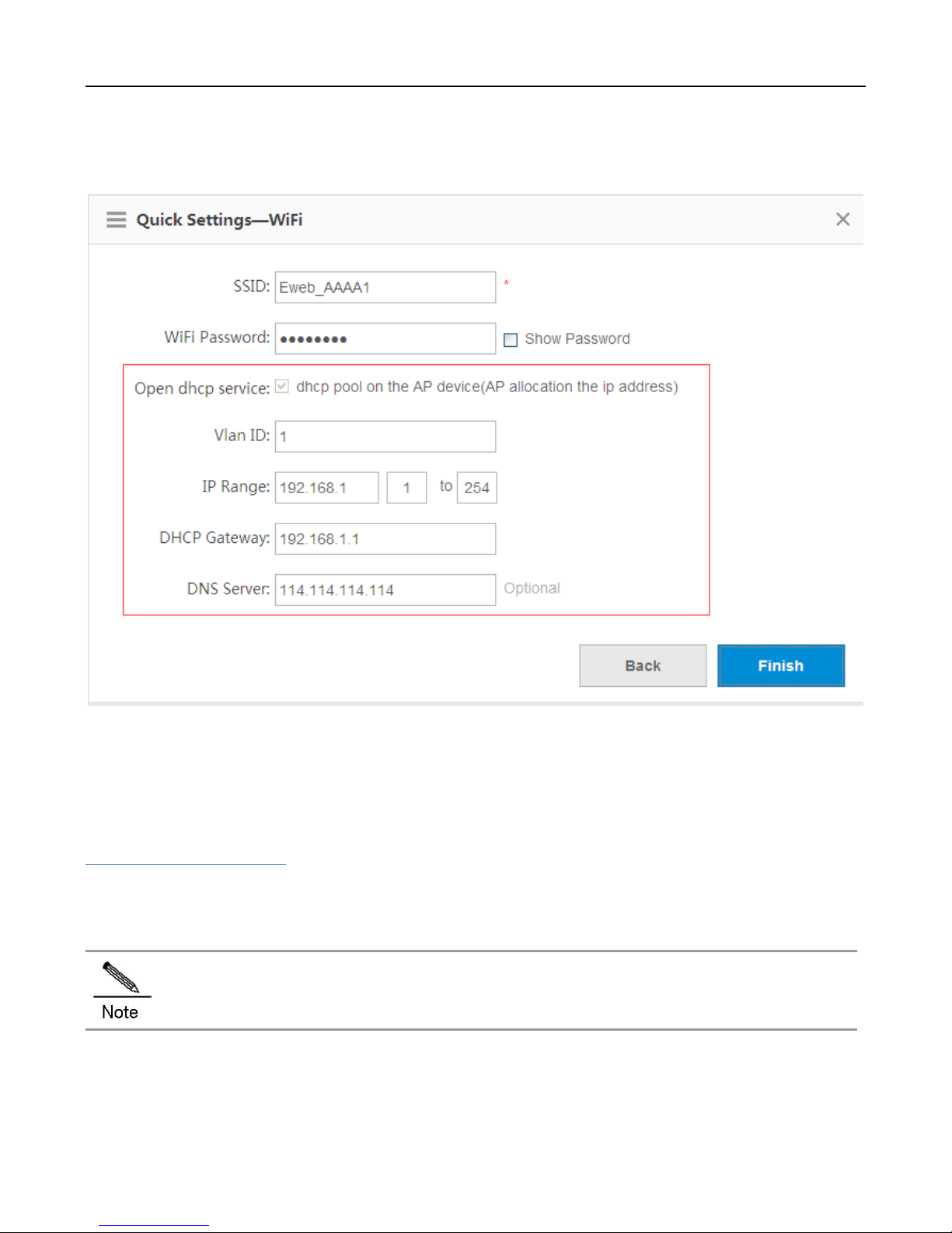
4) DHCP configuration
Figure 1-5 AP Quick Settings for DHCP
IP address range: 192.168.1.0/24 to 192.168.1.254/24.
DNS server: 192.168.58.110 (Perform the configuration based on the actual condition.)
Click Finish.
Verification
Associate an STA with WiFi: Eweb_AAAA1 and obtain the IP address 192.168.1.4.
Verify that the STA can connect to the WiFi and then visit the Web through 192.168.1.1.
If the management IP address is changed, use the new management IP address to visit the Web again.
 Loading...