

Ruijie RG-S2928G-E, RG-S2952G-E, RG-S2928G-12P, RG-S2928G-24P Hardware Installation And Reference Manual

RG-S2900G-E Series Switch
Hardware Installation and Reference Guide V1.25

Copyright Statement
Ruijie Networks©2017
Ruijie Networks reserves all copyrights of this document. Any reproduction, excerption, backup, modification,
transmission, translation or commercial use of this document or any portion of this document, in any form or by any means,
without the prior written consent of Ruijie Networks is prohibited.
Exemption Statement
This document is provided “as is”. The contents of this document are subject to change without any notice. Please obtain
the latest information through the Ruijie Networks website. Ruijie Networks endeavors to ensure content accuracy and will
not shoulder any responsibility for losses and damages caused due to content omissions, inaccuracies or errors.

Preface
Thank you for using our products. This manual will guide you through the installation of the device.
This manual describes the functional and physical features and provides the device installation steps, hardware
troubleshooting, module technical specifications, and specifications and usage guidelines for cables and connectors.
Audience
It is intended for the users who have some experience in installing and maintaining network hardware. At the same time, it
is assumed that the users are already familiar with the related terms and concepts.
Obtaining Technical Assistance
Ruijie Networks Website: http://www.ruijienetworks.com/
Service Email: service_rj@ruijienetworks.com
Technical Support: http://www.ruijienetworks.com/service.aspx
Technical Support Hotline: +86-4008-111-000
Related Documents
Documents
Description
Configuration Guide
Describes network protocols and related mechanisms that supported by the
product, with configuration examples.
Command Reference
Describes the related configuration commands, including command modes,
parameter descriptions, usage guides, and related examples.
Symbol Conventions
Means reader take note. Notes contain helpful suggestions or references.
Means reader be careful. In this situation, you might do something that could result in equipment damage or loss of
data.
1 Product Overview
RG-S2900G-E Series switch is a next-generation security and intelligent switch that features high performance, high
security, multiple services and ease of use to meet the needs of the current networks. The RG-S2900G-E switch can
provide the complete end-to-end Quality of Service (QoS), flexible and abundant security policies and policy-based
network management for various networks. They are the desired access devices for such applications as campus network,
enterprise network, government network, service network, residential broadband access and business building network,
providing high-speed, high-efficiency, secure and intelligent access solutions.
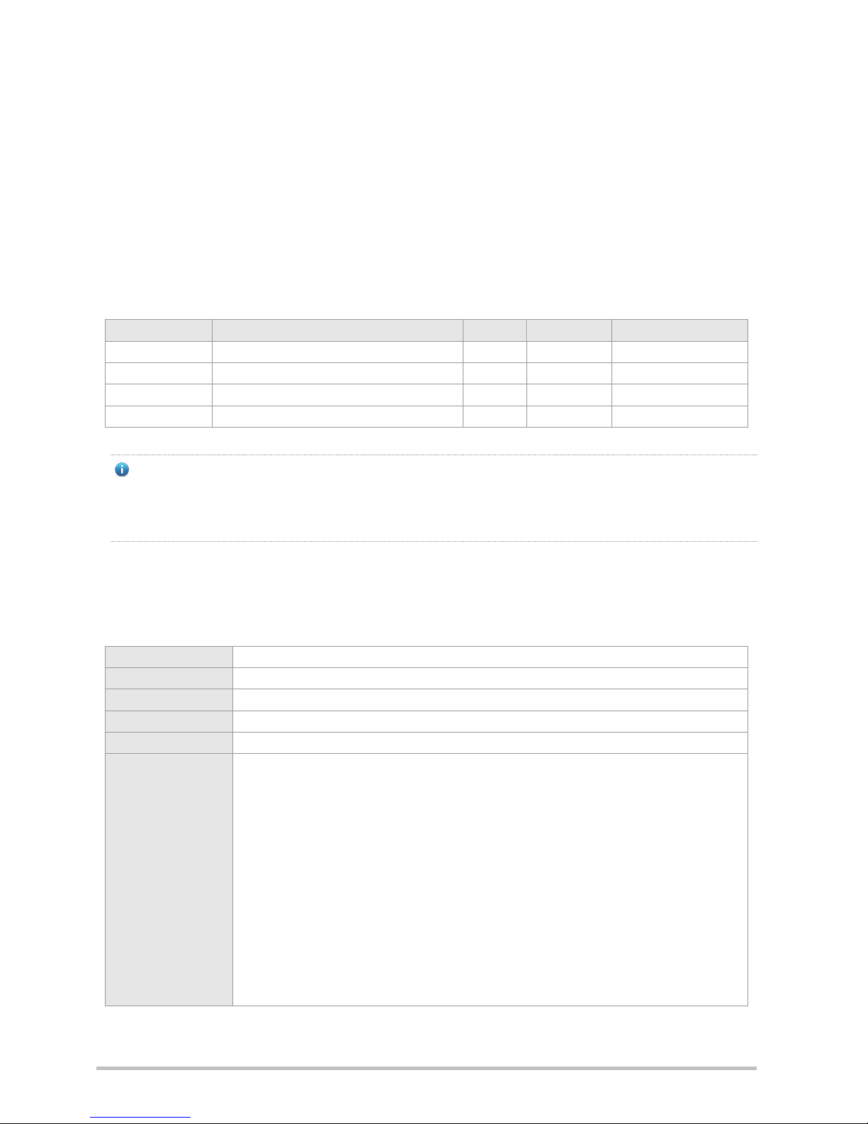
Table 1-1 RG-S2900G-E Series
Model
10/100/1000 Base-T Adaptive Ethernet Port
SFP Port
Console Port
Extension Module Slot
RG-S2928G-E
24 4 1
N/A
RG-S2952G-E
48 4 1
N/A
RG-S2928G-12P
24 4 1
N/A
RG-S2928G-24P
24 4 1
N/A
The four SFP ports support 100Base-FX/1000Base-X/1000Base-T, and the two SFP ports with larger port number
(27F and 28F for the S2928G Series, and 51F and 52F for the S2952 Series) also support 2.5 G stack modules.
Only the four SFP ports of the RG-S2928G-E V2.00 and RG-S2952G-E V2.00 and later, RG-S2928G-12P and
RG-S2928G-24P support 100Base-FX.
1.1 RG-S2928G-E
Technical Specifications
Model
RG-S2928G-E
CPU
Single-core CPU, clock speed of 600M
BOOTROM
8M
Flash Memory
128M
SDRAM
DDRII 128MB
Supported SFP
Type
Gigabit Ethernet:
MINI-GBIC-SX-MM850
MINI-GBIC-LX-SM1310
MINI-GBIC-LH40-SM1310
MINI-GBIC-ZX50-SM1550
MINI-GBIC-ZX80-SM1550
MINI-GBIC-ZX100-SM1550
Fast Ethernet:
FE-SFP-LX-MM1310
FE-SFP-LH15-SM1310
1000Base-T:
Mini-GBIC-GT
2.5G stack module:
GE-SFP-STACK1.6M
The supported module type may change at any time. Consult us for the detailed change
information.
Only the four SFP ports of the RG-S2928G-E V2.00 and later support fast Ethernet SFP
modules.
SFP Port
Support 1000Base-X, 1000Base-T and 2.5 G stacked SFP module
Only the four SFP ports of the RG-S2928G-E V2.00 and later support 100Base-FX.
USB Port
One Type-A USB2.0 interface
Power Supply
AC input:
Rated voltage range: 100 V to 240 V
Maximum voltage range: 90 V to 264 V
Frequency: 50/60 Hz
Rated current: 2A
HVDC input:
Maximum voltage range: 192 V to 290 V
Rated current: 0.2 A to 0.12 A
EEE
Not supported on the RG-S2928G-E V1.00 and later.
Supported on the RG-S2928G-E V2.00 and later.
PoE
Not supported.
Power
Consumption
Less than 33 W on the RG-S2928G-E V1.00 and later.
Less than 27 W on the RG-S2928G-E V2.00 and later.
Working
Temperature
0ºC to 50ºC
Storage
Temperature
-40ºC to 70ºC
Working Humidity
10% to 90% RH
Storage Humidity
5% to 90% RH
Fan
N/A
Temperature
Warning
Supported
EMC Standards
GB9254-1998
Safety Standards
GB4943-2001
Dimensions
(W x D x H)
RG-S2928G-E V1.00 and later: 440 mm x 200 mm x 43.6 mm
RG-S2928G-E V2.00 and later: 440 mm x 260 mm x 43.6 mm

Weight
Less than 3.5 kg
RG-S2928G-E switch is a class A product. In a domestic environment, this product may cause radio interference in
which case the user may be required to take adequate measures.
Product Appearance
The front panel of the RG-S2928G-E full gigabit Ethernet switch provides one Type-A USB2.0 interface, one RJ45
console port, 24 RJ45 10/100/1000Base-T Ethernet adaptive ports and four SFP ports. Figure 1-1 shows the appearance
of the RG-S2928G-E.
Figure 1-1 Appearance of the RG-S2928G-E
Front Panel
Figure 1-2 Front Panel of the RG-S2928G-E
Note:
1. USB2.0 port
2. RJ45 console port
3. RJ45 10/100/1000Base-T adaptive Ethernet
port
4. 100Base-FX/1000Base-X SFP port
5. 100Base-FX/1000Base-X SFP/2.5 G stack port
6. Switch system status indicator
7. 10/100/1000Base-T adaptive Ethernet port indicator
8. 100Base-FX/1000Base-X SFP/2.5 G stack port
indicator
Only the four SFP ports of the RG-S2928G-E V2.00 and later support 100Base-FX.

Back Panel
Figure 1-3 Back Panel of the RG-S2928G-E
Note:
1. Grounding pole
2. Three-hole AC power receptacle
3. Power cord retention clips
Power Supply
The RG-S2928G-E switch can be powered either with AC power or DC power.
AC input:
Rated voltage range: 100 V to 240 V
Maximum voltage range: 90 V to 264 V
Frequency: 50 Hz to 60 Hz
Rated current: 0.6 A
Power cord: 10A power cord
HVDC input:
Maximum voltage range: 192 V to 290 V
Rated current: 0.2 A to 0.12 A
Power cord: 10A power cord
Heat Dissipation
The RG-S2928G-E full gigabit switch is designed with no fans. To ensure good dissipation, sufficient space (10 cm
distance from both sides and the back panel of the chassis) should be reserved for ventilation. Dust the device every three
months to avoid blocking the ventilation openings.
When installing the device, sufficient ventilation space (1 U (44.45 mm) distance from the adjacent device) should be
reserved for the purpose of heat dissipation.
LED Indicators
Indicator
Faceplate
Marker
Status
Indication
Status indicator
Status
Blinking green
The system is being initialized.
Solid green
The system is in normal operation. .

Indicator
Faceplate
Marker
Status
Indication
Solid yellow
System over-temperature warning.
Solid red
Serious over-temperature, the system will stop
working forcibly by itself.
10/100/1000 Mbps RJ-45 port
indicator
1~24
Off
The port is NOT connected.
Solid green
The port is connected at 1000Mbps.
Solid yellow
The port is connected at 100/10Mbps.
Blinking
The port is transmitting or receiving data.
100Base-FX/1000Base-X/Stack
port indicator
(Note: Only the four SFP ports
of the RG-S2928G-E V2.00 and
later support 100Base-FX.)
25F~28F
Off
The port is NOT connected.
Solid green
The port is connected.
Blinking
The port is transmitting or receiving data.
1.2 RG-S2952G-E
Technical Specifications
Model
RG-S2952G-E
CPU
Single-core CPU, clock speed of 600M
BOOTROM
8M
Flash Memory
128M
SDRAM
DDRII 128MB
Supported
SFP Type
Gigabit Ethernet:
MINI-GBIC-SX-MM850
MINI-GBIC-LX-SM1310
MINI-GBIC-LH40-SM1310
MINI-GBIC-ZX50-SM1550
MINI-GBIC-ZX80-SM1550
MINI-GBIC-ZX100-SM1550
Fast Ethernet:
FE-SFP-LX-MM1310
FE-SFP-LH15-SM1310
1000Base-T:
Mini-GBIC-GT
2.5 G stack module:
GE-SFP-STACK1.6M
The supported module type may change at any time. Contact us for the detailed change

information.
Only the four SFP ports of the RG-S2952G-E V2.00 and later support fast Ethernet SFP
modules.
SFP Port
Support 1000 Base-X, 1000 Base-T, 100 Base-FX and 2.5 G stacked SFP module
Only the four SFP ports of the RG-S2952G-E V2.00 and later support 100Base-FX.
USB Port
One Type-A USB2.0 interface
Power Supply
AC input:
Rated voltage range: 100 V to 240 V
Maximum voltage range: 90 V to 264 V
Frequency: 50/60 Hz
Rated current: 2 A
HVDC input:
Maximum voltage range: 192 V to 290 V
Rated current: 0.3 A to 0.17 A
EEE
Not supported on the RG-S2952G-E V1.00 and later
Supported on the RG-S2952G-E V2.00 and later
PoE
Not supported.
Power
Consumption
Less than 59 W on the RG-S2952G-E V1.00 and later
Less than 49 W on the RG-S2952G-E V2.00 and later
Working
Temperature
0ºC to 50ºC
Storage
Temperature
-40ºC to 70ºC
Working
Humidity
10% RH to 90% RH
Storage
Humidity
5% RH to 90% RH
Fan
Support adjustment of fan speed and warning of fan troubles.
Temperature
Warning
Supported
EMC
Standards
GB9254-1998
Safety
Standards
GB4943-2001
Dimensions
(W x D x H)
440 mm x 260 mm x 43.6 mm
Weight
Less than 4 kg

RG-S2952G-E switch is a class A product. In a domestic environment, this product may cause radio interference in
which case the user may be required to take adequate measures.
Product Appearance
The front panel of the RG-S2952G-E full gigabit Ethernet switch provides one Type-A USB2.0 port, one RJ45 console port,
48 RJ45 10/100/1000Base-T adaptive Ethernet ports and four SFP ports. Figure 1-4 shows the appearance of the
RG-S2952G-E.
Figure 1-4 Appearance of the RG-S2952G-E
Front Panel
Figure 1-5 Front Panel of the RG-S2952G-E
Note:
1. USB2.0 port
2. RJ45 console port
3. RJ45 10/100/1000Base-T adaptive
Ethernet port
4. 100 Base-FX/1000 Base-X SFP port
5. 100 Base-FX/1000 Base-X SFP/2.5 G stack port
6. System status indicator
7. 10/100/1000 Base-T adaptive Ethernet port indicator
8. 100Base-FX/1000Base-X SFP/2.5 G stack port
indicator
Only the four SFP ports of the RG-S2952G-E V2.00 and later support 100 Base-FX.
Back Panel
Figure 1-6 Back Panel of the RG-S2952G-E V1.00 and Later

Figure 1-7 Back Panel of the RG-S2952G-E V2.00 and Later
Note:
1. Grounding pole
2. Three-hole AC power receptacle
3. Power cord retention clips
4. Fan outlet
Power Supply
The RG-S2952G-E can be powered either with AC power or DC power.
AC input:
Rated voltage range: 100 V to 240 V
Maximum voltage range: 90 to 264 V
Frequency: 50 Hz to 60 Hz
Rated current: 1.5 A
Power cord: 10A power cord
HVDC input:
Maximum voltage range: 192 V to 290 V
Rated current: 0.3 A to 0.17 A
Power cord: 10A power cord
Heat Dissipation
The RG-S2952G-E full gigabit switch adopts fans for heat dissipation, thereby ensuring the device to function normally in
the specified environment. Sufficient space (10 cm distance from both sides and the back panel of the chassis) should be
reserved for ventilation. Dust the device every three months to avoid blocking the ventilation openings.
Figure 1-8 Heat Dissipation of the RG-S2952G-E

LED Indicators
Indicator
Faceplate Marker
Status
Indication
Status indicator
Status
Blinking green
The system is being initialized.
Solid green
The system is in normal operation.
Solid yellow
System over-temperature warning.
Solid red
Serious over-temperature, the system will stop
working forcibly by itself. Or the fan fault occurs.
10/100/1000Mbps
RJ-45 port indicator
1~48
Off
The port is NOT connected.
Solid green
The port is connected at 1000Mbps.
Solid yellow
The port is connected at 100/10Mbps.
Blinking
The port is transmitting or receiving data.
100 Base-FX/1000
Base-X/Stack port
indicator
(Note: Only the four
SFP ports of the
RG-S2952G-E V2.00
and later support
100Base-FX.)
49F~52F
Off
The port is NOT connected.
Solid green
The port is connected.
Blinking
The port is transmitting or receiving data.
1.3 RG-S2928G-12P
Technical Specifications
Model
RG-S2928G-12P
CPU
Single-core CPU, clock speed of 600M
BOOTROM
8M
Flash Memory
128M

SDRAM
DDRII 128MB
Supported SFP Type
Gigabit Ethernet:
MINI-GBIC-SX-MM850
MINI-GBIC-LX-SM1310
MINI-GBIC-LH40-SM1310
MINI-GBIC-ZX50-SM1550
MINI-GBIC-ZX80-SM1550
MINI-GBIC-ZX100-SM1550
Fast Ethernet:
FE-SFP-LX-MM1310
FE-SFP-LH15-SM1310
1000 Base-T:
Mini-GBIC-GT
2.5 G stack module:
GE-SFP-STACK1.6M
The supported module type may change at any time. Contact us for the detailed
change information.
SFP Port
Support 1000 Base-X, 1000 Base-T, 100 Base-FX and 2.5 G stacked SFP module
USB Port
One Type-A USB2.0 interface
Power Supply
AC input:
Rated voltage range: 100 V to 240 V
Maximum voltage range: 90 V to 264 V
Frequency: 50/60 Hz
Rated current: 3 A
HVDC input:
Maximum voltage range: 192 V to 290 V
Rated current: 2 A to 1.5 A
EEE
Supported.
PoE
Supported standards: IEEE 802.3af and 802.3at
Maximum output power of a single port: 30 W
Maximum PoE/PoE + output power: 185 W
Power Consumption
Less than 229 W with PoE full load.
Less than 32.7 W without PoE
Working Temperature
0ºC to 50ºC
Storage Temperature
-40ºC to 70ºC
Working Humidity
10% RH to 90% RH
Storage Humidity
5% RH to 90% RH
Fan
Support adjustment of fan speed and warning of fan troubles.
Temperature Warning
Supported
EMC Standards
GB9254-1998
Safety Standards
GB4943-2001
Dimensions (W x D x H)
440 mm x 260 mm x 43.6 mm
Weight
Less than 4.5 kg
RG-S2928G-12P switch is a class A product. In a domestic environment, this product may cause radio interference
in which case the user may be required to take adequate measures.
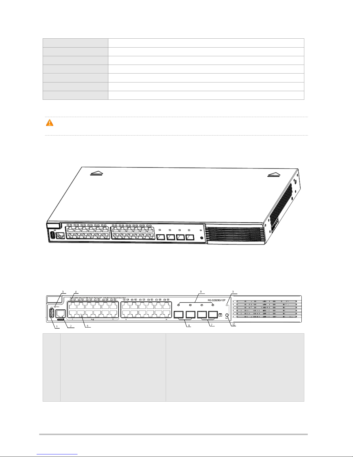
Product Appearance
Figure 1-9 Appearance of the RG-S2928G-12P
Front Panel
Figure 1-10 Front Panel of the RG-S2928G-12P
Note:
1. USB2.0 port
2. RJ45 console port
3. System status indicator
4. 10/100/1000Base-T adaptive Ethernet port
indicator
5. RJ45 10/100/1000Base-T adaptive
Ethernet port (only the 12 ports in the yellow
frame support 802.3af and 802.3at PoE)
6. 100Base-FX/1000Base-X SFP port
7. 100Base-FX/1000Base-X SFP/2.5 G stack port
8. 100Base-FX/1000Base-X SFP/2.5 G stack port indicator
9. PoE mode indicator
10. PoE/switched mode indicator switchover button (By
default, the switch port indicator indicates the switched mode.
You can press this button to switch the status of indicator
between switched mode and PoE mode.)

Back Panel
Figure 1-11 Back Panel of the RG-S2928G-12P
Note:
1. Grounding pole
2. Fan outlet
3. Three-hole AC power receptacle
4. Power cord retention clips
Power Supply
The RG-S2928G-12P can be powered either with AC power or DC power.
AC input:
Rated voltage range: 100 V to 240 V
Maximum voltage range: 90 V to 264 V
Frequency: 50 Hz to 60 Hz
Rated current: 3 A
Power cord: 10A power cord.
HVDC input:
Maximum voltage range: 192 V to 290 V
Rated current: 2 A to 1.5 A
Power cord: 10A power cord
Heat Dissipation
The RG-S2928G-12P switch adopts axial fans for heat dissipation, thereby ensuring the device to function normally in the
specified environment. Sufficient space (10 cm distance from both sides and the back panel of the chassis) should be
reserved for ventilation. Dust the device every three months to avoid blocking the ventilation openings.
Figure 1-12 Heat Dissipation of the RG-S2928G-12P

When installing the device, sufficient ventilation space (1 U (44.45 mm) distance from the adjacent device) should be
reserved for the purpose of heat dissipation.
PoE
The PoE power supply of the RG-S2928G-12P switch is designed to support the IEEE802.3af and 802.3at standards. It
uses Alternative A, that is, uses pins 1&2 and 3&6 to transmit power.
LED Indicators
Indicator
Faceplate Marker
Status
Meaning
PoE/switching
mode indicator
PoE
Solid green
Switching mode.
Solid yellow
PoE mode.
Status indicator
Status
Blinking green
The system is being initialized.
Solid green
The system is operational.
Solid yellow
System over-temperature warning.
Solid red
Serious over-temperature, the system will stop
working forcibly by itself. Or the fan fault occurs.
10/100/1000 Mbps
RJ-45 port indicator
1~24
Off
The port is NOT connected.
Solid green
The port is connected at 1000Mbps.
Solid yellow
The port is connected at 100/10Mbps.
Blinking
The port is transmitting or receiving data.
PoE status indicator
1~12
Off
No PoE power supply.
Solid green
PoE is operational.
Solid yellow
Abnormal PoE power supply
100 Base-FX/1000
Base-X/Stack port
indicator
25F to 28F
Off
The port is NOT connected.
Solid green
The port is connected.
Blinking
The port is transmitting or receiving data.

1.4 RG-S2928G-24P
Technical Specifications
Model
RG-S2928G-24P
CPU
Single-core CPU, clock speed of 600M
BOOTROM
8M
Flash Memory
128M
SDRAM
DDRII 128MB
Supported SFP
Type
Gigabit Ethernet:
MINI-GBIC-SX-MM850
MINI-GBIC-LX-SM1310
MINI-GBIC-LH40-SM1310
MINI-GBIC-ZX50-SM1550
MINI-GBIC-ZX80-SM1550
MINI-GBIC-ZX100-SM1550
Fast Ethernet:
FE-SFP-LX-MM1310
FE-SFP-LH15-SM1310
1000 Base-T:
Mini-GBIC-GT
2.5 G stack module:
GE-SFP-STACK1.6M
The supported module type may change at any time. Contact us for the detailed change
information.
SFP Port
Support 1000 Base-X, 1000 Base-T , 100 Base-FX and 2.5 G stacked SFP module
USB Port
One Type-A USB2.0 interface
Power Supply
AC input:
Rated voltage range: 100 V to 240 V
Maximum voltage range: 90 V to 264 V
Frequency: 50/60 Hz
Rated current: 6A
HVDC input:
Maximum voltage range: 192 V to 290 V
Rated current: 3.5 A to 2.5 A
PoE
Supported standards: IEEE 802.3af and 802.3at
Maximum output power of a single port: 30 W

Maximum PoE/PoE + output power: 370 W
EEE
Supported.
Power
Consumption
Less than 480 W with PoE full load.
Less than 45 W without PoE
Working
Temperature
0ºC to 50ºC
Storage
Temperature
-40ºC to 70ºC
Working Humidity
10% RH to 90% RH
Storage Humidity
5% RH to 90% RH
Fan
Support adjustment of fan speed and warning of fan troubles.
Temperature
Warning
Supported
EMC Standards
GB9254-1998
Safety Standards
GB4943-2001
Dimensions
(W x D x H)
440 mm x 260 mm x 43.6 mm
Weight
Less than 4.5 kg
RG-S2928G-24P switch is a class A product. In a domestic environment, this product may cause radio interference
in which case the user may be required to take adequate measures.
Product Appearance
Figure 1-13 Appearance of the RG-S2928G-24P
Front Panel

Figure 1-14 Front Panel of the RG-S2928G-24P
Note:
1. USB2.0 port
2. RJ45 console port
3. System status indicator
4. 10/100/1000 Base-T adaptive Ethernet
port indicator
5. RJ45 10/100/1000 Base-T adaptive
Ethernet port (all of the 24 ports support
802.3af and 802.3at PoE)
6. 100 Base-FX/1000 Base-X SFP port
7. 100 Base-FX/1000 Base-X SFP/2.5 G stack port
8. 100 Base-FX/1000 Base-X SFP/2.5 G stack port indicator
9. PoE mode indicator
10. PoE/switched mode indicator switchover button (By default,
the switch port indicator indicates the switched mode. You can
press this button to switch the status of indicator between
switched mode and PoE mode.)
Back Panel
Figure 1-15 Back Panel of the RG-S2928G-24P
Note:
1. Grounding pole
2. Fan outlet
3. Three-hole AC power receptacle
4. Power cord retention clips
Power Supply
The RG-S2928G-24P can be powered either with AC power or DC power.
AC input:
Rated voltage range: 100 V to 240 V
Maximum voltage range: 90 V to 264 V
Frequency: 50 Hz to 60 Hz
Rated current: 6.8 A (Max)
Power cord: 10A power cord
HVDC input:
Maximum voltage range: 192 V to 290 V
Rated current: 3.5 A to 2.5 A
Power cord: 10A power cord

Heat Dissipation
The RG-S2928G-24P switch adopts axial fans for heat dissipation, thereby ensuring the device to function normally in the
specified environment. Sufficient space (10 cm distance from both sides and the back panel of the chassis) should be
reserved for ventilation. Dust the device every three months to avoid blocking the ventilation openings.
Figure 1-16 Heat Dissipation of the RG-S2928G-24P
When installing the device, sufficient ventilation space (1 U (44.45 mm) distance from the adjacent device) should be
reserved for the purpose of heat dissipation.
PoE
The PoE power supply of the RG-S2928G-24P switch is designed to support the IEEE802.3af and 802.3at standards. It
uses Alternative A, that is, uses pins 1&2 and 3&6 to transmit power.
LED Indicators
Indicator
Faceplate Marker
Status
Indication
PoE/switching mode indicator
PoE
Solid green
Switching mode.
Solid yellow
PoE mode.
Status indicator
Status
Blinking green
The system is being initialized.
Solid green
The system is operational.
Solid yellow
System over-temperature warning.
Solid red
Serious over-temperature, the system
will stop working forcibly by itself. Or the
fan fault occurs.
10/100/1000Mbps RJ-45 port
indicator
1~24
Off
The port is NOT connected.
Solid green
The port is connected at 1000Mbps.
Solid yellow
The port is connected at 100/10Mbps.
Blinking
The port is transmitting and receiving
data.

Indicator
Faceplate Marker
Status
Indication
PoE status indicator
1~24
Off
No PoE power supply.
Solid green
PoE is operational.
Solid yellow
Abnormal PoE power supply
100Base-FX/1000Base-X/Stack
port indicator
25F~28F
Off
The port is NOT connected.
Solid green
The port is connected.
Blinking
The port is transmitting and receiving
data.

2 Preparation before Installation
2.1 Safety Suggestions
To avoid personal injury and equipment damage, please carefully read the safety suggestions before you install the
RG-S2900G-E series.
The following safety suggestions do not cover all possible dangers.
2.1.1 Safety Precautions for Installing the System
Keep the chassis clean and free from any dust.
Do not place the equipment in a walking area.
Do not wear loose clothes or accessories that may be hooked or caught by the device during installation and
maintenance.
Turn off all power supplies and remove the power sockets and cables before installing or uninstalling the device.
2.1.2 Movement Safety
Do not frequently move the device.
When moving the device, note the balance and avoid hurting legs and feet or straining the back.
Before moving the device, turn off all power supplies and dismantle all power modules.
2.1.3 Electric Safety
Observe local regulations and specifications when performing electric operations. Relevant operators must be
qualified.
Before installing the device, carefully check any potential danger in the surroundings, such as ungrounded power
supply, and damp/wet ground or floor.
Before installing the device, find out the location of the emergency power supply switch in the room. First cut off the
power supply in the case of an accident.
Try to avoid maintaining the switch that is powered-on alone.
Be sure to make a careful check before you shut down the power supply.
Do not place the equipment in a damp location. Do not let any liquid enter the chassis.
1. Any nonstandard and inaccurate electric operation may cause an accident such as fire or electrical shock, thus
causing severe even fatal damages to human bodies and equipment.
2. Direct or indirect touch through a wet object on high-voltage and mains supply may bring a fatal danger.

2.1.4 Static Discharge Damage Prevention
To prevent damage from static electricity, pay attention to the following:
Proper grounding of grounding screws on the back panel of the device. Use of a three-wire single-phase socket with
protective earth wire (PE) as the AC power socket.
Indoor dust prevention
Proper humidity conditions
2.1.5 Laser Safety
The RG-S2900G-E series switch supports varying models of optical modules sold on the market which are Class I laser
products. Improper use of optical modules may cause damage. Therefore, pay attention to the following when you use
them:
When a fiber transceiver works, ensure that the port has been connected with an optical fiber or is covered with a
dust cap, to keep out dust and avoid burning your eyes.
When the optical module is working, do not pull out the fiber cable and stare into the transceiver interface or you may
hurt your eyes.
Do not stare into any optical port under any circumstances, as this may cause permanent damage to your eyes.
2.2 Installation Site Requirements
To ensure the normal working and a prolonged durable life of the equipment, the installation site must meet the following
requirements.
2.2.1 Ventilation Requirements
For the RG-S2900G-E series, you must ensure that sufficient space (10 cm distance from both sides and the back panel
of the cabinet) is reserved at the ventilation openings to ensure the normal ventilation. During the jumper process of the
device, prevent the cables from blocking the cellular heat dissipation holes around the device. Be especially careful for the
RG-S2928G-E device. This high-speed forwarding device adopts the fan-free design; therefore, it has high requirement
for heat dissipation of the operating environment. Dust the device every three months to avoid blocking the ventilation
openings.
2.2.2 Temperature and Humidity Requirements
To ensure the normal operation and prolong the service life of RG-S2900G-E series, you should keep proper temperature
and humidity in the equipment room.
If the equipment room has temperature and humidity that do not meet the requirements for a long time, the equipment
may be damaged.
In an environment with high relative humidity, the insulating material may have bad insulation or even leak electricity.
Sometimes the materials may suffer from mechanical performance change and metallic parts may get rusted.

In an environment with low relative humidity, however, the insulating strip may dry and shrink. Static electricity may
occur easily and endanger the circuit on the equipment.
In an environment with high temperature, the equipment is subject to even greater harm, as its performance may
degrade significantly and various hardware faults may occur. .
Therefore, the ambient temperature and humidity of the RG-S2900G-E must meet the requirements listed in Table 2-1:
Table 2-1 Temperature and Humidity Requirements of the RG-S2900G-E Series
Temperature
Relative Humidity
0ºC to 50ºC
10% RH to 90% RH
The requirements for the sampling site of the temperature and humidity in the operating environment of the device
are as follows:
There is no protective plate at the front or back of the equipment rack.
The vertical height is 1.5 m above the floor.
The distance from the front panel of the equipment is 0.4 m.
2.2.3 Cleanness Requirements
Dust poses a severe threat to the running of the equipment. The indoor dust falling on the equipment may be adhered by
the static electricity, causing bad contact of the metallic joint. Such electrostatic adherence may occur more easily when
the relative humidity is low, not only affecting the useful life of the equipment, but also causing communication faults.
Table 2-2 shows the requirements for the dust content and granularity in the equipment room.
Table 2-2 Requirements for the Dust Content and Granularity in the Equipment Room
Substance
Concentration Limit (particles/m3)
Dust particles (diameter ≥0.5μm)
≤3.5×10⁶
Dust particles (diameter ≥5μm)
≤3×10⁴
Apart from dust, the salt, acid and sulfide in the air in the equipment room must also meet strict requirements; as such
poisonous substances may accelerate the corrosion of the metal and the aging of some parts. The equipment room
should be protected from the intrusion of harmful gases (for example, SO2, H2S, NO2 and Cl2), whose requirements are
listed in the following table.
Table 2-3 Requirements for Harmful Gases in the Equipment Room
Gas
Average (mg/m3)
Maximum (mg/m3)
SO2
0.3
1.0
H2S
0.1
0.5
NO2
0.5
1.0
Cl2
0.1
0.3

The Average refers to the average limit of harmful gas in one week. The Maximum value is the upper limit of the
harmful gas measured in one week for up to 30 minutes every day.
2.2.4 EMI
During applications, the switch may be subject to external interferences that affect the device through conduction manners
such as capacitance coupling, inductive coupling, electromagnetic wave emission, common impedance (including
grounding systems), and wires (power cables, signal cables and outgoing transmission cables). For that purpose, note
that:
For the AC power supply system TN, single-phase three-core power socket with protective earthing conductors (PE)
should be adopted to effectively filter out interference from the power grid through the filtering circuit.
The switch should be located at places free from large power radio launch pad, radar launch pad, and
high-frequency large-current devices.
If necessary, electromagnetic shielding should be adopted. For example, use interface cables to shield cables.
Interface cables should be laid inside the equipment room. Outdoor cabling is prohibited, avoiding damages to
device signal interfaces caused by over-voltage or over-current of lightning.
2.2.5 System Grounding Requirements
A good grounding system is the basis for the stable and reliable operation of the RG-S2900G-E series. It is the chief
condition to prevent lightning stroke and resist interference. Please carefully check the grounding conditions on the
installation site according to the grounding requirements, and perform grounding operations properly as required.
Effective grounding of the switch is an important guarantee for lightning protection and interference resistance.
Therefore, connect the grounding line of the switch properly..
Safety Grounding
The equipment using AC power supply must be grounded by using the yellow/green safety grounding cable. Otherwise,
when the insulating resistance decreases the power supply and the enclosure in the equipment, electric shock may occur.
Lightning Grounding
The lightning protection system of a facility is an independent system that consists of the lightning rod, downlead
conductor and the connector to the grounding system, which usually shares the power reference ground and yellow/green
safety cable ground. The lightning discharge ground is for the facility only, irrelevant to the equipment.
EMC Grounding
The grounding required for EMC design includes shielding ground, filter ground, noise and interference suppression, and
level reference. All the above constitute the comprehensive grounding requirements. The resistance of earth wires should
be less than 1 ohm. The RG-S2900G-E backplane is reserved with one grounding pole, as shown in Figure 2-1.

Figure 2-1 Schematic Diagram of the RG-S2900G-E Grounding
2.2.6 Lightning Resistance Considerations
When the AC power cable is imported outdoors and directly connected to the power port of the switch, lightning line bank
should be adopted to prevent the switch from being hit by lightning shocks. Usage of the lightning line bank: Connect the
mains supply AC cable to the lightning line bank. Then, connect the switch to the lightning line bank. This can help to
prevent the current of high-voltage lightning from passing the switch directly through the mains supply cable to a certain
extent.
The lightning line banks are not provided and should be purchased by users as required.
For the usage of lightning line banks, refer to their related manuals.
2.2.7 EMI Consideration
Electro-Magnetic Interference (EMI), from either outside or inside the equipment or application system, affects the system
in the conductive ways such as capacitive coupling, inductive coupling, and electromagnetic radiation.
There are two types of electromagnetic interferences: radiated interference and conducted interference, depending on the
type of the transmission path.
When the energy, often RF energy, from a component arrives at a sensitive component via the space, the energy is
known as radiated interference. The interference source can be either a part of the interfered system or a completely
electrically isolated unit. Conducted interference results from the electromagnetic wire or signal cable connection between
the source and the sensitive component, along which cable the interference conducts from one unit to another. Conducted
interference often affects the power supply of the equipment, but can be controlled by a filter. Radiated interference may
affect any signal path in the equipment and is difficult to shield.
Effective measures should be taken for the power system to prevent the interference from the electric grid.
The grounding device of the switch must not be used as the grounding device of the electrical equipment or
anti-lightning grounding device. In addition, the grounding device of the switch must be deployed far away from the
grounding device of the electrical equipment and anti-lightning grounding device.
Keep the equipment away from high-power radio transmitter, radar transmitting station, and high-frequency
large-current device.
Measures must be taken to shield static electricity.

2.3 Requirements of Installation Tools
Table 2-4 List of Installation Tools
Common tools
Philips screwdriver, flathead screwdriver, related electric cables and optical cables, bolts, diagonal
pliers, straps
Special tools
Anti-static tools
Meters
Multimeter
The tool kit is customer supplied.

3 Product Installation
Please ensure that you have carefully read the section of “Preparation before Installation”.
Make sure that the requirements set forth in section of “Preparation before Installation” have been met.
3.1 Installation Procedure
3.2 Confirmations before Installation
Before installation, please confirm the following points:
Whether ventilation requirements are met for the switch
Whether the requirements of temperature and humidity are met for the switch
Whether power cables are already laid out and whether the requirements of electrical current are met
Whether related network adaption lines are already laid out
3.3 Installing the RG-S2900G-E Series
Precautions
Install the RG-S2900G-E to the rack
Connect the system grounding
Connect the power supply
Connect the external interface cable
Bundle the cables.
Check the installation
End

During installation, note the following points:
Connect the power cables of different colors to the corresponding grounding posts.
Ensure that the interface of the power supply cable is well connected to the power interface of the device. The power
cables must be protected using power cable retention clips after they are connected to the device.
Do not place any articles on the RG-S2900G-E series switch.
Reserve a spacing of at least 10 cm around the chassis for good ventilation. Do not stack the devices.
The switch should be located at places free from the large power radio launch pad, radar launch pad, and
high-frequency large-current devices. If necessary, electromagnetic shielding should be adopted. For example, use
interface cables to shield cables.
100-meter network cables should be laid inside the equipment room and outdoor cabling of such cables is prohibited.
If outdoor cabling is necessary, take relevant measures for lightning protection..
3.3.1 Mounting the Switch in the Rack
The RG-S2900G-E series switches are designed with the EIA standard dimensions and can be installed in 19-inch rack.
Attach the mounting brackets to the switch with the supplied screws, as shown in Figure 3-2.
Figure 3-2 Attaching the Mounting Bracket to the Switch
3.3.2 Mounting the Switch on the Wall
The RG-S2900G-E series switches can be mounted on a wall.
Attach the mounting brackets to the switch with the supplied screws, as shown in Figure 3-3.
Figure 3-3 Attaching the Mounting Brackets to the Switch for Wall-Mounting

3.4 Checking after Installation
Before checking the installation, switch off the power supply so as to avoid any personal injury or damage to the
component due to connection errors.
Check that the ground line is connected.
Check that the cables and power input cables are correctly connected.
Check that the 100 meter cables are laid out inside the equipment room. In the case of external cabling, check that
the lightning resistance socket or network interface lightning protector is connected.
Check that sufficient ventilation space is available around the device (over 10 cm).

4 System Debugging
4.1 Establishing the Debugging Environment
Establishing the Debugging Environment
Connect the PC to the console port of the switch through the console cable, as shown in Figure 4-1.
Figure 4-1 Schematic Diagram of the Configuration Environment
Connecting the Console Cable
Step 1: Connect the end of the console cable with DB-9 jack to the serial port of the PC.
Step 2: Connect the end of the console cable with RJ45 to the console port of the switch.
Setting HyperTerminal Parameters
Step 1: Start the PC and run the terminal simulation program on the PC, such as Terminal on Windows 3.1 or
HyperTerminal on Windows 95/98/NT/2000/XP.
Step 2: Set terminal parameters. The parameters are as follows: baud rate 9600, data bit 8, parity check none, stop
bit 1, and flow control as none.
Choose Setup > Program > Attachment > Communication > Hyper Terminal.
Choose Cancel, the interface as shown in Figure 4-2 is displayed.
Figure 4-2

Enter the name of the new connection and click OK, the interface as shown in Figure 4-3 is displayed. Choose the serial
port used currently in the column [use when connecting].
Figure 4-3
After choosing the serial port, click OK to display the serial port parameter setting interface, set the baud rate to 9600,
data bit to 8, parity check to none, stop bit to 1 and flow control to none.
Figure 4-4

After setting the parameters, click OK to enter the hyper terminal interface.
4.2 Startup Check
4.2.1 Checking before the Device is Powered on
The routing host is fully grounded.
The power cable is correctly connected.
The power supply voltage complies with the requirement of the switch.
The control cable of the PC is properly connected to the console port of the switch. The hyper terminal is started and
the parameter settings are correct.
4.2.2 Checking after Program Startup (Recommended)
After power-on, you are recommended to perform the following checks to ensure the normal operation of follow-up
configurations.
Check whether information is displayed on the terminal interface.
Check whether the status of the switch indicator is normal.
Check whether the main program of the device is normally loaded.
Check whether the time on the device is consistent with the current Beijing time.
Check whether the gigabit Ethernet electrical interface forwards data normally.

5 Maintenance and Troubleshooting
5.1 General Troubleshooting Procedure
5.2 Troubleshooting Common Faults
Symptom
Possible Causes
Solution
Forgetting the
management interface
login password
A password is manually configured but
it is forgotten.
Please contact Ruijie Networks Customer Service
Department for technical support.
The status indicator is
not on after the switch
is started.
The power supply module does not
supply power.
The power cable is in loose contact.
Check whether the power socket at the equipment
room is normal and whether the power cable of the
switch is in good contact.
The status indicator is
red.
Fan alarm
Temperature alarm
Check whether the fan is blocked or damaged.
At this time, the switch already stops the normal
service exchanges. Check in time the working
environment of the switch, clean the dust on the
cabinet and reinforce the refrigeration effect.

Symptom
Possible Causes
Solution
The serial port
console has no output
or outputs illegible
characters.
The serial port connected to the switch
does not match that opened by the
configuration software.
The serial port is not configured
correctly.
Change the serial port opened by the configuration
software to be the one connected to the switch.
Check that the parameter configuration of the serial
port matches that specified in the instructions.
The RJ45 port is not in
connectivity or it is
erroneous in
receiving/transmitting
frames.
The connected twisted pair cable is
faulty.
The length of the cable exceeds 100 m.
The port has special configuration that
has no common working mode with the
connected switch.
Replace the twisted pair cable.
Check that the port configuration has the common
working mode with the connected switch.
The fiber port cannot
be connected.
The Rx and Tx ends are connected
reversely.
The interconnected optical module type
does not match.
The fiber type is not correct.
The length of the optical fiber exceeds
that rated of the optical module.
Switch the Rx and Tx ends of the optical fiber.
Replace the optical module with one of the
matched type.
Replace the optical fiber with one of the
appropriate type.
Replace the optical fiber with one of the
appropriate length.
The PoE port cannot
be powered.
The PoE function is not enabled.
The connected twisted pair is faulty.
The PD (that is, the powered device,
for example, AP) connected to the port
does not comply with the 802.3af or
802.3at standard.
The serial port control terminal
connected to the PD is not properly
grounded.
The switch is not properly grounded.
Enter interface configuration mode and enable the
PoE function.
Replace the twisted pair.
Replace the current PD with a PD that complies
with the 802.3af or 802.3at standard. For the
RG-S2928G-12P/24P switch, you can enable the
PoE non-standard compatible function to power
the PD.
Ground the serial port control terminal properly and
ensure that the switch is properly grounded. For
the RG-S2928G-12P/24P switch, you can enable
the PoE non-standard compatible function to
power the PD.
Ground the switch properly.
The PoE port indicator
is yellow.
The PD is short-circuited or overloaded
and its power exceeds the power value
distributed to this port by the PoE
switch.
The total power of the PDs connected
to the switch exceeds the rated power
range provided by the PoE switch.
Check whether the rated power of the PD is within
the output power range of the switch. If yes, set the
power distributed to the port by the switch to a
larger value. If the problem persists after the
setting, the PD is damaged. In this case, replace
the PD.
Determine the total power of the PDs. To power a
certain port preferentially, set the priority of this
port to a higher value.

Appendix A: Connectors and Connection Media
1000BASE-T/100BASE-TX/10BASE-T Ports
The 1000BASE-T/100BASE-TX/10BASE-T is a port that supports adaptation of three rates, and automatic MDI/MDIX
Crossover at these three rates.
The 1000BASE-T complies with IEEE 802.3ab, and uses the cable of 100-ohm Category-5 or Supper Category-5 UTP or
STP, which can be up to 100 m.
The 1000BASE-T port uses four pairs of wires for transmission, all of which must be connected. Figure A-1 shows the
connections of the twisted pairs used by the 1000BASE-T port.
Figure A-1 Four Twisted Pairs of the 1000BASE-T
Straight-Through
Crossover
Switch Switch
Switch Switch
1 TP0 + 1 TP0 +
1 TP0 + 1 TP0 +
2 TP0 - 2 TP0 -
2 TP0 - 2 TP0 -
3 TP1 + 3 TP1 +
3 TP1 + 3 TP1 +
6 TP1 - 6 TP1 -
6 TP1 - 6 TP1 -
4 TP2 + 4 TP2 +
4 TP2 + 4 TP2 +
5 TP2 - 5 TP2 -
5 TP2 - 5 TP2 -
7 TP3 + 7 TP3 +
7 TP3 + 7 TP3 +
8 TP3 - 8 TP3 -
8 TP3 - 8 TP3 -
In addition to the above cables, the 100BASE-TX/10BASE-T can also use 100-ohm Category-3, 4, 5 cables for 10 Mbps,
and 100-ohm Category-5 cables for 100 Mbps, both of which can be up to 100 m. Figure A-2 shows the pinouts of the
100BASE-TX/10BASE-T.
Figure A-2 Pinouts of the 100BASE-TX/10BASE-T
Pin
Socket
Plug
1
Input Receive Data+
Output Transmit Data+
2
Input Receive Data-
Output Transmit Data-
3
Output Transmit Data+
Input Receive Data+
6
Output Transmit Data-
Input Receive Data-
4, 5, 7, 8
Not Used
Not Used
Figure A-3 shows the straight-through and crossover cable connections for the 100BASE-TX/10BASE-T.
Figure A-3 Connections of the Twisted Pairs of the 100BASE-TX/10BASE-T

Straight-Through
Crossover
Switch Switch
Switch Switch
1 IRD + 1 OTD +
1 IRD + 1OTD +
2 IRD - 2 OTD -
2 IRD - 2OTD -
3 OTD + 3 IRD +
3 OTD + 3 IRD +
6 OTD - 6 IRD -
6 OTD - 6 IRD +
2. Optical Fiber Connection
For the optical fiber ports, select single-mode or multiple-mode optical fibers for connection according to the fiber module
connected. The connection schematic diagram is shown in Figure A-4:
Figure A-4 Optical Fiber Connections
Switch Switch
TX TX
RX RX

Appendix B Mini-GBIC Modules
We provide appropriate 1000M SFP modules (Mini-GBIC) modules according to the types of interfaces of the switch
modules. You can select the SFP module to suit your specific needs. The following models and technical specifications of
some 1000M SFP modules are listed for your reference.
Models and Technical Specifications of the Mini-GBIC (SFP) Module
Table B-1 Models and Technical Specifications of the SFP Module
Mini-GBIC
( SFP )
Wavelength
( nm )
Media
Type
Core
Size
( μm )
Modal
Bandwidth
( MHz/km )
Cabling
Distance
Intensity of
Transmitted
Light
( dbm )
MAX
Intensity of
Received
Light
( dbm )
MAX
Standard
Complian
ce
MINI-GBIC-S
X-MM850
850
Multimode
fiber
62.5
62.5
50.0
50.0
160
200
400
500
220 m
275 m
500 m
550 m
-4
-17
IEEE802.
3
MINI-GBIC-L
X-SM1310
1310
Multi-
mode
fiber
62.5
50.0
50.0
500
400
500
550 m
550 m
550 m
-3
-20
Single-
mode
fiber
9/10
N/A
10 km
MINI-GBIC-L
H40-SM1310
1310
Singlemode
fiber
9/125
N/A
40 km
3
-3
MINI-GBIC-Z
X50-SM1550
1550
Singlemode
fiber
N/A
N/A
50 km
0
-22
MINI-GBIC-Z
X80-SM1550
80 km
4.7
-22
MINI-GBIC-Z
X100-SM155
0
100 km
5
-9
Mini-GBIC-G
T N/A
CAT 5
UTP
N/A
N/A
100 m
N/A
N/A
For the optical module with transmission distance exceeding 40 km and more, one on-line optical attenuator should
be added on the link to avoid the overload of the optical receiver when short single-mode optical fibers are used.

Appendix C Site Selection
The machine room should be at least 5km away from the heavy pollution source such as the smelter, coal mine and
thermal power plant, 3.7km away from the medium pollution source such as the chemical industry, rubber industry
and electroplating industry, and 2km away from the light pollution source such as the food manufacturer and leather
plant. If the pollution source is unavoidable, the machine room should be located on the windward side of the
pollution source perennially with advanced protection.
The machine room should be at least 3.7km away from the sea or salt lake. Otherwise, the machine room must be
sealed, with air conditioner installed for temperature control. Saline soil cannot be used for construction. Otherwise,
you should select devices with advanced protection against severe environment.
Do not build the machine room in the proximity of livestock farms. Otherwise, the machine room should be located
on the windward side of the pollution source perennially. The previous livestock house or fertilizer warehouse cannot
be used as the machine room.
The machine room should be firm enough to withstand severe weather conditions such as windstorm and heavy rain
as well as away from dust. If the dust is unavoidable, keep the door and window away from the pollution source.
The machine room should be away from the residential area. Otherwise, the machine room should meet the
construction standard in terms of noise.
Make sure the air vent of the machine room is away from the sewage pipe, septic tank, and sewage treatment tank.
Keep the machine room under positive pressure to prevent corrosive gas from entering the machine room to corrode
components and circuit boards. Keep the machine room away from industrial boiler and heating boiler.
The machine room had better be on the second floor or above. Otherwise, the machine room floor should be 600mm
higher than the highest flood level ever recorded.
Make sure there are no cracks or holes in the wall and floor. If there are cable entries in the wall or window, take
proper sealing measures. Ensure that the wall is flat, wear-resistant, and dust-free, which should be up to the
standard for flame retarding, soundproofing, heat absorption, dust reduction, and electromagnetic shielding.
Keep the door and the window closed to make the machine room sealed.
The steel door is recommended for soundproofing.
Sulfur-containing materials are forbidden.
Pay attention to the location of the air conditioner. Keep the air conditioner from blowing wind straight toward the
device or blowing water drops from the window or air vent toward the device.
 Loading...