

Ruijie RG-S2910-48GT4XS-E, RG-S2910-10GT2SFP-UP-H, RG-S2910C-24GT2XS-P-E, RG-S2910C-24GT2XS-HP-E, RG-S2910C-48GT2XS-HP-E Hardware Installation And Reference Manual
...
RG-S2910-H Series Switch
Hardware Installation and Reference Guide V1.22

Copyright Statement
Ruijie Networks©2017
Ruijie Networks reserves all copyrights of this document. Any reproduction, excerption, backup,
modification, transmission, translation or commercial use of this document or any portion of this document,
in any form or by any means, without the prior written consent of Ruijie Networks is prohibited.
Exemption Statement
This document is provided “as is”. The contents of this document are subject to change without any notice.
Please obtain the latest information through the Ruijie Networks website. Ruijie Networks endeavors to
ensure content accuracy and will not shoulder any responsibility for losses and damages caused due to
content omissions, inaccuracies or errors.

Preface
Thank you for using our products. This manual will guide you through the installation of the device.
This manual describes the functional and physical features and provides the device installation steps,
hardware troubleshooting, module technical specifications, and specifications and usage guidelines for
cables and connectors.
Audience
It is intended for the users who have some experience in installing and maintaining network hardware. At
the same time, it is assumed that the users are already familiar with the related terms and concepts.
Obtaining Technical Assistance
Ruijie Networks Website: http://www.ruijienetworks.com/
Service Email: service_rj@ruijienetworks.com
Technical Support: http://www.ruijienetworks.com/service.aspx
Technical Support Hotline: +86-4008-111-000
Related Documents
Documents
Description
Configuration Guide
Describes network protocols and related mechanisms that
supported by the product, with configuration examples.
Command Reference
Describes the related configuration commands, including
command modes, parameter descriptions, usage guides, and
related examples.
Symbol Conventions
The symbols used in this document are described as below:
This symbol brings your attention to some helpful suggestions and references.
This symbol means that you must be extremely careful not to do some things that may damage the
device or cause data loss

1 Product Overview
The RG-S2910-H series switch is a next-generation intelligent switch that features high performance, high security,
multiple services and ease of use to meet the needs of the current networks. The RG-S2910-H series switch can provide
the complete end-to-end Quality of Service (QoS), flexible and abundant security policies and policy-based network
management for various networks. It is greatly ideal for such applications as campus network, enterprise network,
government network, service network, residential broadband access and business building network, providing high-speed,
high-efficiency, secure and intelligent access solutions.
Table 1-1 RG-S2910-H
Model
10/100/1000 Base-T
Auto-sensing Ethernet Port
SFP+
Port
1000Base-X
SFP Port
Console
Port
USB
Port
Pluggable
Power
Slot
RG-S2910-24GT4SFP-UP-H
24 (All are PoE+ capable.
Ports 1-4 are HPoE capable)
\ 4 1 \ \
RG-S2910-10GT2SFP-UP-H
10 (Ports 1-8 are HPoE
capable)
\ 2 1 \ \
RG-S2910-24GT4XS-UP-H
24 (All are PoE+ capable.
Ports 1-4 are HPoE capable)
4 \ 1 \ \
The SPF+ ports are downward compatible with 1000Base-X. The SFP ports only support 1000Base-X modules.
1000Base-T is compatible with 100Base-TX and 10Base-T in the downlink direction.
For RG-S2910-24GT4SFP-UP-H /RG-S2910-24GT4XS-UP-H, the HPoE ports support 60W power supply and
support IEEE 802.af/at PoE.
For RG-S2910-10GT2SFP-UP-H, the HPoE ports support 95W power supply and support IEEE 802.af/at PoE.
1.1 RG-S2910-24GT4SFP-UP-H
Technical Specifications
Model
RG-S2910-24GT4SFP-UP-H
CPU
Built-in CPU, single-core processor, 1GHz
Flash Memory
512M
SDRAM
DDRIII 512MB
Optical Module
For details, see Appendix B.
The supported module type may change at any time. Consult us for the latest information.
SFP Port
Supports 1000Base-X modules. Does not support 100Base-FX.
When the SFP ports are used as stack ports:
When used as stack ports, SFP ports of hardware versions V1.XX only support 10G DAC

copper cables (XG-SFP-CU1M, XG-SFP-CU3M and XG-SFP-CU5M); SFP ports of
hardware versions V2.XX support 10G DAC copper cables (XG-SFP-CU1M,
XG-SFP-CU3M and XG-SFP-CU5M), 2.5G DAC copper cables (GE-SFP-STACK1.6M),
and SFP transceiver modules.
Power Supply
AC input
Rated voltage range: 100V to 240V
Maximum voltage range: 90V to 264V
Frequency: 50/60 Hz
Rated current: 6.8A
HVDC input
Voltage range: 192V to 290V
Current range: 2.5A to 3.5A
EEE
Supported
PoE
All the RJ45 ports are PoE-capable. Ports 1-4 are HPoE-capable with the maximum power
output of 60W. Ports 5-24 support the maximum power output of 30W.
The maximum output power of PoE/PoE+/HPoE is 370W.
The HPoE ports support the maximum power supply of 60W only when connected with
HPoE PDs. For example, RG-PBOX-DC12 and RG-PBOX-AC24.
HPoE ports support IEEE 802.af/at PoE.
The available number of PDs is determined by PSE output power and PD input power in
practice.
Power
Consumption
Less than 40W with no PoE load
Less than 460W with PoE full load
Operating
Temperature
0℃ to 50℃
Storage
Temperature
-40℃ to 70℃
Operating Humidity
10% to 90%
Storage Humidity
5% to 95%
Fan
Speed adjustment and fault alarm
Temperature
Warning
Supported
EMCStandards
GB9254-2008
EN 300 386
EN 61000-3-2
EN 61000-3-3
EN 61000-4-2
EN 61000-4-3
EN 61000-4-4
EN 61000-4-5

EN 61000-4-6
EN 61000-4-11
EN 55022
EN 55024
EN 61000-4-8
Security Standards
GB4943-2011
EN60950-1
IEC60950-1
Dimensions
(W x D x H)
440 mm x 260 mm x 44 mm
Weight
≤5.5 kg (with package)
The RG-S2910-24GT4SFP-UP-H switch is a class A product. In a domestic environment, this product may cause
radio interference in which case the user may be required to take adequate measures.
Product Appearance
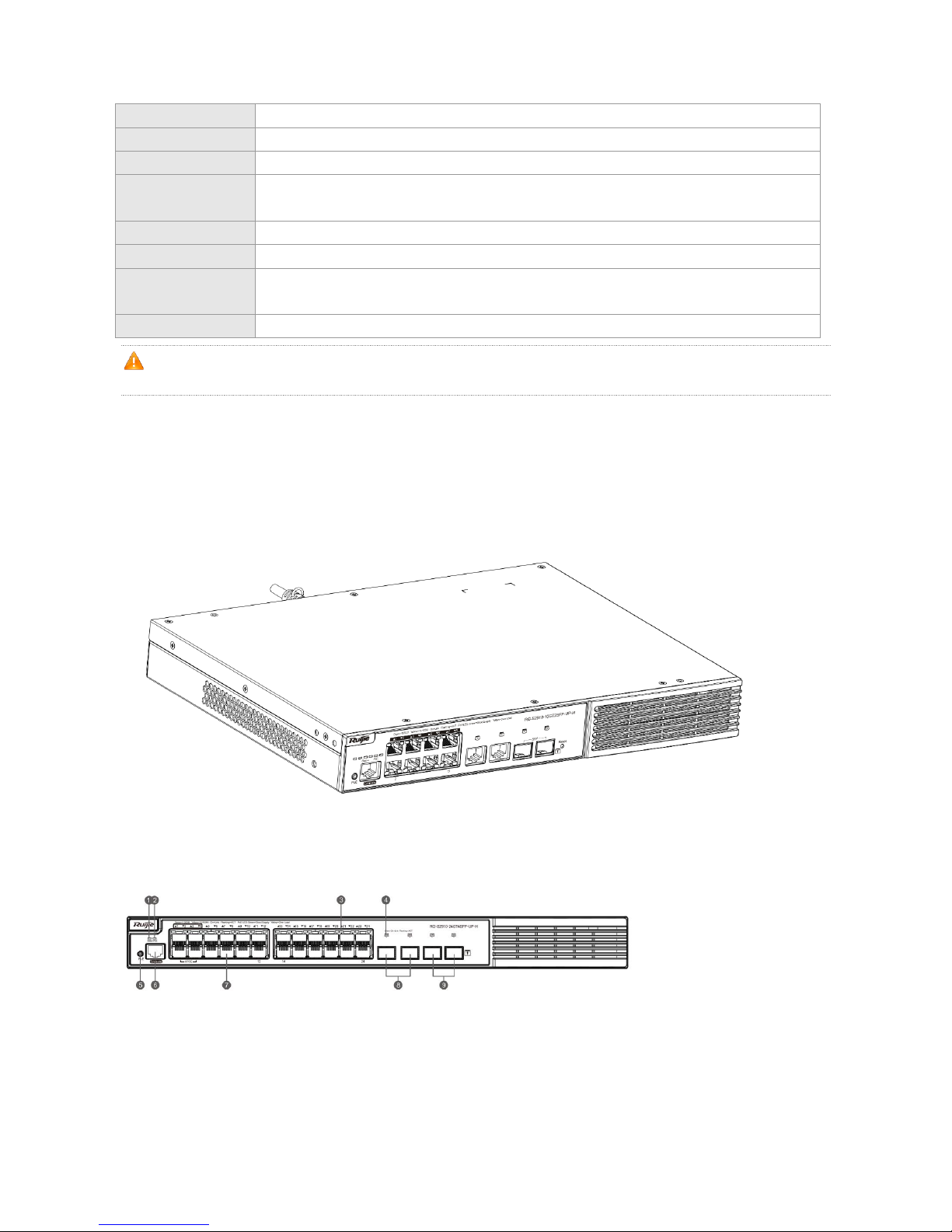
On the front panel, the RG-S2910-24GT4SFP-UP-H Ethernet switch provides 24 10/100/1000Base-T Ethernet ports, 4
SFP ports, and 1 Console port. On the back panel, it provides AC power ports.
Figure 1-1 Appearance of RG-S2910-24GT4SFP-UP-H
Front Panel
Figure 1-2 Front Panel of RG-S2910-24GT4SFP-UP-H

Note:
1. System status LED
2. PoE status LED
3. Copper port status LED
4. Fiber port status LED
5. PoE Mode Switch-Over Button
6. Console port
7. 10/100/1000Base-T auto-sensing Ethernet port
8. 1000Base-X SFP port
9. 1000Base-X SFP port
Long press PoE Mode Switch-Over Button for above 2 seconds to switch the display mode between PoE mode and
port rate mode.
Back Panel
Figure 1-3 Back Panel of RG-S2910-24GT4SFP-UP-H
Note:
1. Grounding pole
Power Supply
The RG-S2910-24GT4SFP-UP-H switch adopts AC or HVDC power input.
AC input
Rated voltage range: 100V to 240V
Maximum voltage range: 90V to 264V
Frequency range: 50/60 Hz
Rated current: 6.8A
Power cord specification: 10A
HVDC input
Voltage range: 192V to 290V
Current range: 2.5A to 3.5A
Heat Dissipation
The RG-S2910-24GT4SFP-UP-H adopts turbine fans for heat dissipation, thereby ensuring normal function of the device
in the specified environment. 10 cm distance space should be reserved at both sides and the back plane of the cabinet to

allow air circulation. It is recommended to clean the device once every 3 months to avoid dust from blocking vents. Figure
1-4 shows the flow scheme of heat dissipation.
Figure 1-4 Flow Scheme of Heat Dissipation
LEDs
LED
Panel Identification
State
Meaning
System status LED
Status
Off
The switch is not receiving power.
Blinking green
The system is being initialized.
Continuous blinking indicates errors.
Solid green
The switch is operational.
Solid yellow
Temperature warning
Check the working environment of the switch
immediately.
Solid red
The switch is faulty.
PoE status LED
PoE
Solid green
Indicates the switching state.
Solid yellow
Indicates the PoE state.
1-24
Off
The port is not connected.

1000Mbps RJ-45 port
status LED
Solid green
The port is connected at 1000 Mbps.
Blinking green
The port is receiving or transmitting traffic at 1000
Mbps.
Solid yellow
The port is connected at 10/100 Mbps.
Blinking yellow
The port is receiving or transmitting traffic at
10/100 Mbps.
RJ45 port PoE status
LED
1-24
Off
PoE is not enabled.
Solid green
PoE is enabled. The port is operational.
Solid yellow
The PoE port is abnormally operational.
1000Mbps SFP port
status LED
25F-28F
Off
The port is not connected.
Solid green
The port is connected at 1000 Mbps.
Blinking green
The port is receiving or transmitting traffic at 1000
Mbps.
1.2 RG-S2910-24GT4XS-UP-H
Technical Specifications
Model
RG-S2910-24GT4XS-UP-H
CPU
Built-in CPU, single-core processor, 1GHz
Flash Memory
512M
SDRAM
DDRIII 512MB
Optical Module
For details, see Appendix B.
The supported module type may change at any time. Consult us for the latest information.
SFP Port
Supports 10GBase-R and 1000Base-X modules.
When used as stack ports, SFP+ ports support 10G DAC copper cables (XG-SFP-CU1M,
XG-SFP-CU3M, and XG-SFP-CU5M) and SFP+ transceiver modules.
Power Supply
AC input
Rated voltage range: 100V to 240V
Maximum voltage range: 90V to 264V
Frequency: 50/60 Hz
Rated current: 6.8A

HVDC input
Voltage range: 192V to 290V
Current range: 2.5A to 3.5A
EEE
Supported
PoE
All the RJ45 ports are PoE-capable. Ports 1-4 are HPoE-capable with the maximum power
output of 60W. Ports 5-24 support the maximum power output of 30W.
The maximum output power of PoE/PoE+/HPoE is 370W.
The HPoE ports support the maximum power supply of 60W only when connected with
HPoE PDs. For example, RG-PBOX-DC12 and RG-PBOX-AC24.
HPoE ports support IEEE 802.af/at PoE.
The available number of PDs is determined by PSE output power and PD input power in
practice.
Power
Consumption
Less than 40W with no PoE load
Less than 460W with PoE full load
Operating
Temperature
0℃ to 50℃
Storage
Temperature
-40℃ to 70℃
Operating Humidity
10% to 90%
Storage Humidity
5% to 95%
Fan
Speed adjustment and fault alarm
Temperature
Warning
Supported
EMCStandards
GB9254-2008
Security Standards
GB4943-2011
Dimensions
(W x D x H)
440 mm x 260 mm x 44 mm
Weight
≤5.5 kg (with package)
The RG-S2910-24GT4XS-UP-H switch is a class A product. In a domestic environment, this product may cause
radio interference in which case the user may be required to take adequate measures.
Product Appearance
On the front panel, the RG-S2910-24GT4XS-UP-H Ethernet switch provides 24 10/100/1000Base-T Ethernet ports, 4
SFP+ ports, and 1 Console port. On the back panel, it provides AC power ports.
Figure 1-5 Appearance of RG-S2910-24GT4XS-UP-H

Front Panel
Figure 1-6 Front Panel of RG-S2910-24GT4XS-UP-H
Note:
1. System status LED
2. PoE status LED
3. Copper port status LED
4. Fiber port status LED
5. PoE Mode Switch-Over Button
6. Console port
7. 10/100/1000Base-T auto-sensing Ethernet port
8. SFP+ port
Long press PoE Mode Switch-Over Button for above 2 seconds to switch the display mode between PoE mode and
port rate mode.
Back Panel
Figure 1-7 Back Panel of RG-S2910-24GT4XS-UP-H
Note:
1. Grounding pole
Power Supply
The RG-S2910-24GT4XS-UP-H switch adopts AC or HVDC power input.
AC input

Rated voltage range: 100V to 240V
Maximum voltage range: 90V to 264V
Frequency range: 50/60 Hz
Rated current: 6.8A
Power cord specification: 10A
HVDC input
Voltage range: 192V to 290V
Current range: 2.5A to 3.5A
Heat Dissipation
The RG-S2910-24GT4XS-UP-H adopts turbine fans for heat dissipation, thereby ensuring normal function of the device in
the specified environment. 10 cm distance space should be reserved at both sides and the back plane of the cabinet to
allow air circulation. It is recommended to clean the device once every 3 months to avoid dust from blocking vents. Figure
1-8 shows the flow scheme of heat dissipation.
Figure 1-8 Flow Scheme of Heat Dissipation
LEDs
LED
Panel Identification
State
Meaning
System status LED
Status
Off
The switch is not receiving power.

Blinking green
The system is being initialized.
Continuous blinking indicates errors.
Solid green
The switch is operational.
Solid yellow
Temperature warning
Check the working environment of the switch
immediately.
Solid red
The switch is faulty.
PoE status LED
PoE
Solid green
Indicates the switching state.
Solid yellow
Indicates the PoE state.
1000Mbps RJ-45 port
status LED
1-24
Off
The port is not connected.
Solid green
The port is connected at 1000 Mbps.
Blinking green
The port is receiving or transmitting traffic at 1000
Mbps.
Solid yellow
The port is connected at 10/100 Mbps.
Blinking yellow
The port is receiving or transmitting traffic at
10/100 Mbps.
RJ45 port PoE status
LED
1-24
Off
PoE is not enabled.
Solid green
PoE is enabled. The port is operational.
Solid yellow
The PoE port is abnormally operational.
SFP+ port status LED
25F-28F
Off
The port is not connected.
Solid green
The port is connected.
Blinking green
The port is receiving or transmitting traffic.

1.3 RG-S2910-10GT2SFP-UP-H
Technical Specifications
Model
RG-S2910-10GT2SFP-UP-H
CPU
Built-in CPU, single-core processor, 400MHz
Flash Memory
256M
SDRAM
DDRIII 512MB
Optical Module
Supports 1000base-X only. For details, see Appendix B.
The supported module type may change at any time. Consult us for the latest information.
SFP Port
Supports 1000Base-X modules.
Power Supply
AC input
Rated voltage range: 100V to 240V
Maximum voltage range: 90V to 264V
Frequency: 50/60 Hz
Rated current: 8A
HVDC input
Voltage range: 192V to 290V
Current range: 0A to 6A
EEE
Supported
PoE
Ports 1-8 are HPoE-capable with the maximum power output of 95W.
The maximum output power is as follows.
AC input
90 to175VAC: 380W
175 to 264VAC: 760W
HVDC input
192 to 220VDC: 380W
220 to 290VDC: 760W
The HPoE ports support the maximum power supply of 95W only when connected with
HPoE PDs. For example, RG-PBOX-DC12 and RG-PBOX-AC24.
HPoE ports support IEEE 802.af/at PoE.
The available number of PDs is determined by PSE output power and PD input power in
practice.
Power
Consumption
Less than 30W with no PoE load
Less than 870W with full PoE load
Operating
Temperature
0℃ to 50℃
Storage
Temperature
-40℃ to 70℃
Operating Humidity
10% to 90%
Storage Humidity
5% to 95%
Fan
Speed adjustment and fault alarm
Temperature
Warning
Supported
EMCStandards
GB9254-2008
Security Standards
GB4943-2011
Dimensions
(W x D x H)
340 mm x 260 mm x 44 mm
Weight
≤4.0 kg (with package)
The RG-S2910-10GT2SFP-UP-H switch is a class A product. In a domestic environment, this product may cause
radio interference in which case the user may be required to take adequate measures.
Product Appearance
On the front panel, the RG-S2910-10GT2SFP-UP-H Ethernet switch provides 10 10/100/1000Base-T Ethernet ports, 2
SFP ports, and 1 Console port. On the back panel, it provides AC power ports.
Figure 1-9 Appearance of RG-S2910-10GT2SFP-UP-H
Front Panel
Figure 1-10 Front Panel of RG-S2910-10GT2SFP-UP-H

Note:
1. System status LED
2. PoE status LED
3. 10/100/1000Base-T auto-sensing Ethernet
port
4. Copper port status LED
5. Copper port status LED
6. Fiber port status LED
7. PoE Mode Switch-Over Button
8. Console port
9. 10/100/1000Base-T auto-sensing Ethernet port
10. 1000Base-X SFP port
11. Reset Button
Long press PoE Mode Switch-Over Button for above 2 seconds to switch the display mode between PoE mode and
port rate mode.
Back Panel
Figure 1-11 Back Panel of RG-S2910-10GT2SFP-UP-H
Note:
Grounding pole
Air exhaust
Air exhaust
Power Supply
The RG-S2910-10GT2SFP-UP-H switch adopts AC or HVDC power input.
AC input
Rated voltage range: 100V to 240V
Maximum voltage range: 90V to 264V
Frequency range: 50/60 Hz
Rated current: 8A
Power cord specification: 10A

HVDC input
Voltage range: 192V to 290V
Current range: 0A to 6A
Heat Dissipation
The RG-S2910-10GT2SFP-UP-H adopts turbine fans for heat dissipation, thereby ensuring normal function of the device
in the specified environment. 10 cm distance space should be reserved at both sides and both planes of the cabinet to
allow air circulation. It is recommended to clean the device once every 3 months to avoid dust from blocking vents. Figure
1-12 shows the flow scheme of heat dissipation.
Figure 1-12 Flow Scheme of Heat Dissipation
LEDs
LED
Panel Identification
State
Meaning
System status LED
Status
Off
The switch is not receiving power.
Blinking green
The system is being initialized.
Continuous blinking indicates errors.
Solid green
The switch is operational.

Solid yellow
Temperature warning
Check the working environment of the switch
immediately.
Solid red
The switch is faulty.
PoE status LED
PoE
Solid green
Indicates the switching state.
Solid yellow
Indicates the PoE state.
1000Mbps RJ-45 port
status LED
1-10
Off
The port is not connected.
Solid green
The port is connected at 1000 Mbps.
Blinking green
The port is receiving or transmitting traffic at 1000
Mbps.
Solid yellow
The port is connected at 10/100 Mbps.
Blinking yellow
The port is receiving or transmitting traffic at
10/100 Mbps.
RJ45 port PoE status
LED
1-8
Off
PoE is not enabled.
Solid green
PoE is enabled. The port is operational.
Solid yellow
The PoE port is abnormally operational.
1000Mbps SFP port
status LED
11F-12F
Off
The port is not connected.
Solid green
The port is connected at 1000 Mbps.
Blinking green
The port is receiving or transmitting traffic at 1000
Mbps.

2 Preparation before Installation
2.1 Safety Suggestions
To avoid personal injury and equipment damage, please carefully read the safety suggestions before you install the
RG-S2910-H series switch.
The following safety suggestions do not cover all possible dangers.
2.1.1 Installation
Keep the chassis clean and free from any dust.
Do not place the equipment in a walking area.
Do not wear loose clothes or accessories that may be hooked or caught by the device during installation and
maintenance.
Turn off all power supplies and remove the power sockets and cables before installing or uninstalling the device.
2.1.2 Movement
Do not frequently move the device.
When moving the device, note the balance and avoid hurting legs and feet or straining the back.
Before moving the device, turn off all power supplies and dismantle all power modules.
2.1.3 Electricity
Observe local regulations and specifications when performing electric operations. Relevant operators must be
qualified.
Before installing the device, carefully check any potential danger in the surroundings, such as ungrounded power
supply, and damp/wet ground or floor.
Before installing the device, find out the location of the emergency power supply switch in the room. First cut off the
power supply in the case of an accident.
Try to avoid maintaining the switch that is powered-on alone.
Be sure to make a careful check before you shut down the power supply.
Do not place the equipment in a damp location. Do not let any liquid enter the chassis.
Any nonstandard and inaccurate electric operation may cause an accident such as fire or electrical shock, thus
causing severe even fatal damages to human bodies and equipment.
Direct or indirect touch through a wet object on high-voltage and mains supply may bring a fatal danger.

2.1.4 Static Discharge Damage Prevention
To prevent damage from static electricity, pay attention to the following:
Proper grounding of grounding screws on the back panel of the device. Use of a three-wire single-phase socket with
protective earth wire (PE) as the AC power socket.
Indoor dust prevention
Proper humidity conditions
2.1.5 Laser
The RG-S2910-H series switch supports varying models of optical modules sold on the market which are Class I laser
products. Improper use of optical modules may cause damage. Therefore, pay attention to the following when you use
them:
When a fiber transceiver works, ensure that the port has been connected with an optical fiber or is covered with a
dust cap, to keep out dust and avoid burning your eyes.
When the optical module is working, do not pull out the fiber cable and stare into the transceiver interface or you may
hurt your eyes.
Do not stare into any optical port under any circumstances, as this may cause permanent damage to your eyes.
2.2 Installation Site Requirements
To ensure the normal working and a prolonged durable life of the equipment, the installation site must meet the following
requirements.
2.2.1 Ventilation
For the RG-S2910-H, a sufficient space (at least 10 cm distances from both sides and the back plane of the cabinet)
should be reserved at the ventilation openings to ensure the normal ventilation. After various cables have been connected,
they should be arranged into bundles or placed on the cabling rack to avoid blocking the air inlets. It is recommended to
clean the switch at regular intervals (like once every 3 months). Especially, avoid dust from blocking the screen mesh on
the back of the cabinet.
2.2.2 Temperature and Humidity
To ensure the normal operation and prolong the service life of RG-S2910-H series switch, you should keep proper
temperature and humidity in the equipment room.
If the equipment room has temperature and humidity that do not meet the requirements for a long time, the equipment
may be damaged.
In an environment with high relative humidity, the insulating material may have bad insulation or even leak electricity.
Sometimes the materials may suffer from mechanical performance change and metallic parts may get rusted.
In an environment with low relative humidity, however, the insulating strip may dry and shrink. Static electricity may
occur easily and endanger the circuit on the equipment.

In an environment with high temperature, the equipment is subject to even greater harm, as its performance may
degrade significantly and various hardware faults may occur.
Therefore, the ambient temperature and humidity of the RG-S2910-H series must meet the requirements listed in Table
2-1:
Table 2-1 Temperature and Humidity Requirements of the RG-S2910-H Series Switch
Temperature
Relative Humidity
0 ºC to 50ºC
10% to 90%
The requirements for the sampling site of the temperature and humidity in the operating environment of the device
are as follows:
There is no protective plate at the front or back of the equipment rack.
The vertical height is 1.5 m above the floor.
The distance from the front panel of the equipment is 0.4 m.
2.2.3 Cleanness
Dust poses a severe threat to the running of the equipment. The indoor dust falling on the equipment may be adhered by
the static electricity, causing bad contact of the metallic joint. Such electrostatic adherence may occur more easily when
the relative humidity is low, not only affecting the useful life of the equipment, but also causing communication faults.
Table 2-2 shows the requirements for the dust content and granularity in the equipment room.
Table 2-2 Requirements for the Dust Content and Granularity in the Equipment Room
Dust
Unit
Density
Diameter≥0.5μm
Particles/m3
≤3.5×10⁶
Diameter≥5μm
Particles/m3
≤3×10⁴
Apart from dust, the salt, acid and sulfide in the air in the equipment room must also meet strict requirements, as such
poisonous substances may accelerate the corrosion of the metal and the aging of some parts. The equipment room
should be protected from the intrusion of harmful gases such as sulfur dioxide, sulfured hydrogen, nitrogen dioxide, and
chlorine), whose requirements are listed in Table 2-3.
Table 2-3 Requirements for Harmful Gases in the Equipment Room
Gas
Average (mg/m3)
Maximum (mg/m3)
SO2 0.3
1.0
H2S
0.1
0.5
NO2
0.5
1.0
Cl2
0.1
0.3
Both average and maximum value are measured for a week. The switch cannot be placed in the environment with
the maximum density for over 30 minutes every day. ..
2.2.4 Grounding
A good grounding system is the basis for the stable and reliable operation of the RG-S2910-H series switch. It is the chief
condition to prevent lightning stroke and resist interference. Please carefully check the grounding conditions on the
installation site according to the grounding requirements, and perform grounding operations properly as required.

Effective grounding of the switch is an important guarantee for lightning protection and interference resistance.
Therefore, connect the grounding line of the switch properly.
Safety Grounding
The equipment using AC power supply must be grounded by using the yellow/green safety grounding cable. Otherwise,
when the insulating resistance decreases the power supply and the enclosure in the equipment, electric shock may occur.
The building must provide protective grounding connection to ensure that the device is connected to the protection
location.
The installation and maintenance personnel must check whether the A.C. socket is well connected to the protection
location of the building, if not, they should use a protective grounding wire to connect the grounding end of the A.C.
socket to the building's protection location.
The power supply socket must be installed in a place that is near to the device and where users can operate the
device easily.
Before the installation of the device, make sure that ground connection is connected at first and disconnected finally.
The sectional area of the protective grounding wire should be at least 0.75 mm2 (18 AWG).
Use the 3-core power supply line. The sectional area of each pin should be at least 0.75 mm2 or 18 AWG.
Lightning Grounding
The lightning protection system of a facility is an independent system that consists of the lightning rod, download
conductor and the connector to the grounding system, which usually shares the power reference ground and yellow/green
safety cable ground. The lightning discharge ground is for the facility only, irrelevant to the equipment.
EMC Grounding
The grounding required for EMC design includes shielding ground, filter ground, noise and interference suppression, and
level reference. All the above constitute the comprehensive grounding requirements. The resistance of earth wires should
be less than 1 ohm. The RG-S2910-H series switch back plane is reserved with one grounding pole, as shown in Figure
2-1.
Figure 2-1Grounding of RG-S2910-H
2.2.5 Lightning Resistance
When the AC power cable is imported outdoors and directly connected to the power port of the RG-S2910-H series switch,
lightning line bank should be adopted to prevent the switch from being hit by lightning shocks. Usage of the lightning line
bank: Connect the mains supply AC cable to the lightning line bank. Then, connect the switch to the lightning line bank.

This can help to prevent the current of high-voltage lightning from passing the switch directly through the mains supply
cable to a certain extent.
The lightning line banks are not provided and should be purchased by users as required.
For the usage of lightning line banks, refer to their related manuals.
2.2.6 EMI
Electro-Magnetic Interference (EMI), from either outside or inside the equipment or application system, affects the system
in the conductive ways such as capacitive coupling, inductive coupling, and electromagnetic radiation.
There are two types of electromagnetic interference: radiated interference and conducted interference, depending on the
type of the transmission path.
When the energy, often RF energy, from a component arrives at a sensitive component via the space, the energy is
known as radiated interference. The interference source can be either a part of the interfered system or a completely
electrically isolated unit. Conducted interference results from the electromagnetic wire or signal cable connection between
the source and the sensitive component, along which cable the interference conducts from one unit to another. Conducted
interference often affects the power supply of the equipment, but can be controlled by a filter. Radiated interference may
affect any signal path in the equipment and is difficult to shield.
For the AC power supply system TN, single-phase three-core power socket with protective earthing conductors (PE)
should be adopted to effectively filter out interference from the power grid through the filtering circuit.
The grounding device of the switch must not be used as the grounding device of the electrical equipment or
anti-lightning grounding device. In addition, the grounding device of the switch must be deployed far away from the
grounding device of the electrical equipment and anti-lightning grounding device.
Keep the equipment away from high-power radio transmitter, radar transmitting station, and high-frequency
large-current device.
Measures must be taken to shield static electricity.
Interface cables should be laid inside the equipment room. Outdoor cabling is prohibited, avoiding damages to
device signal interfaces caused by over-voltage or over-current of lightning.
2.3 Requirements of Installation Tools
Table 2-4 List of Installation Tools
Common Tools
Phillips screwdriver, flathead screwdriver, related electric cables and optical cables, bolts, diagonal
pliers, straps
Special Tools
Anti-static tools
Meters
Multimeter
The tool kit is customer-supplied.

3 Product Installation
Please ensure that you have carefully read Chapter 2.
Make sure that the requirements set forth in Chapter 2 have been met.
3.1 Installation Flowchart
3.2 Confirmations before Installation
Before installation, please confirm the following points:
Whether ventilation requirements are met for the switch
Whether the requirements of temperature and humidity are met for the switch
Whether power cables are already laid out and whether the requirements of electrical current are met
Whether related network adaption lines are already laid out
3.3 Installing the RG-S2910-H
Precautions
During installation, note the following points:

Connect the power cables of different colors to the corresponding grounding posts.
Ensure that the interface of the power supply cable is well connected to the power interface of the device. The power
cables must be protected using power cable retention clips after they are connected to the device.
Do not place any articles on the RG-S2910-H series switch.
Reserve a spacing of at least 10 cm around the chassis for good ventilation. Do not stack the devices.
The switch should be located at places free from the large power radio launch pad, radar launch pad, and
high-frequency large-current devices. If necessary, electromagnetic shielding should be adopted. For example, use
interface cables to shield cables.
100-meter network cables should be laid inside the equipment room and outdoor cabling of such cables is prohibited.
If outdoor cabling is necessary, take relevant measures for lightning protection.
3.3.1 Mounting the Switch to a Standard 19-inch Rack
The RG-S2910-H series switches follow the EIA standard dimensions and can be installed in 19-inch distribution cabinets.
Attach the mounting brackets to the switch with the supplied screws, as shown in Figure 3-1.
Figure 3-1 Attaching the Mounting Bracket to the Switch
Align the mounting holes in the mounting bracket with the mounting holes in the rack, as shown in Figure 3-2.
Figure 3-2

Use the supplied M6 screws and cage nuts to securely attach the mounting brackets to the rack, as shown in Figure 3-3.
Figure 3-3
3.3.2 Mounting the Switch on the Wall
The RG-S2910-H series switch can be mounted on the wall, as shown in the following figure.
Attach the mounting brackets to the switch with the supplied screws, as shown in Figure 3-4.
Figure 3-4 Attaching the Mounting Brackets to the Switch for Wall-Mounting

Use the expansion screws to securely attach the mounting brackets on the wall, as shown in Figure 3-5.
Figure 3-4 Attaching the Switch on the Wall
SUITABLE FOR MOUNTING ON CONCRETE OR OTHER NON-COMBUSTIBLE SURFACE ONLY.
3.3.3 Mounting the Switch on a Table
Attach the four rubber feet to the recessed areas on the bottom of the switch, as shown in Figure 3-6.
Figure 3-6 Attaching the Rubber Feet to the Recessed Areas

Place the switch on the table, as shown in Figure 3-7.
Figure 3-7 Mounting the Switch on the Table
The device must be installed and operated in the place that can restrict its movement.
3.4 Checking after Installation
Before checking the installation, switch off the power supply so as to avoid any personal injury or damage to the
component due to connection errors.
Check that the ground line is connected.
Check that the cables and power input cables are correctly connected.
Check that all interface cables are laid out inside the equipment room. In the case of external cabling, check that the
lightning resistance socket or network interface lightning protector is connected.
Check that sufficient airflow is available around the device (over 10 cm)

4 System Debugging
4.1 Establishing the Debugging Environment
Establishing the Debugging Environment
Connect the PC to the console port of the switch through the console cable, as shown in Figure 4-1.
Figure 4-1 Schematic Diagram of the Configuration Environment
Connecting the Console Cable
Step 1: Connect the end of the console cable with DB-9 jack to the serial port of the PC.
Step 2: Connect the end of the console cable with RJ45 to the console port of the switch.
Setting HeperTerminal Parameters
Step 1: Start the PC and run the terminal simulation program on the PC, such as Terminal on Windows 3.1 or
HyperTerminal on Windows 95/98/NT/2000/XP.
Step 2: Set terminal parameters. The parameters are as follows: baud rate 9600, data bit 8, parity check none, stop
bit 1, and flow control as none.
1. Choose Setup>Program>Attachment >Communication> Hyper Terminal.
2. Choose Cancel, the interface as shown in figure 4-2 is displayed.
Figure 4-2
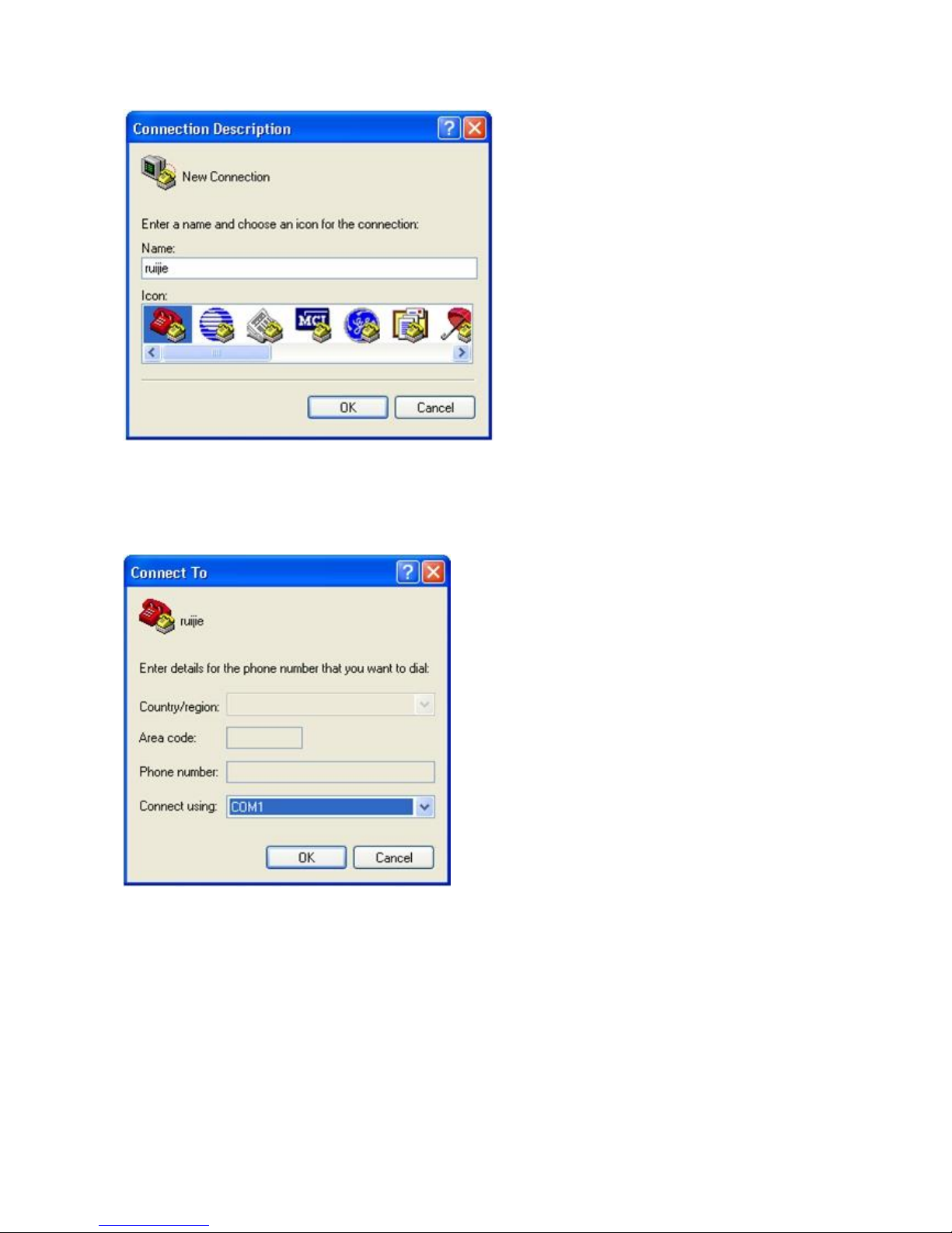
3. Enter the name of the new connection and click OK, the interface as shown in figure 4-3 is displayed. Choose the
serial port used currently in the column [use when connecting].
Figure 4-3
4. After choosing the serial port, click OK to display the serial port parameter setting interface, set the baud rate to 9600,
data bit to 8, parity check to none, stop bit to 1 and flow control to none.
Figure 4-4

5. After setting the parameters, click OK to enter the hyper terminal interface.
4.2 Startup Check
4.2.1 Checking before the Device is Powered on
The switch is fully grounded.
The power cable is correctly connected.
The power supply voltage complies with the requirement of the switch.
The control cable of the PC is properly connected to the console port of the switch. The HyperTerminal is started and
the parameter settings are correct.
4.2.2 Checking after Program Startup (Recommended)
After power-on, you are recommended to perform the following checks to ensure the normal operation of follow-up
configurations.
Check whether information is displayed on the terminal interface.
Check whether the status of the switch indicator is normal.
Check whether the main program of the device is normally loaded.
Check whether the time on the device is consistent with the current Beijing time.

Check whether the service interface forwards data normally.

5 Maintenance and Troubleshooting
5.1 General Troubleshooting Procedure
5.2 Troubleshooting Common Faults
Symptom
Possible Causes
Solution
Forgetting the
management interface
login password
A password is manually configured but
it is forgotten.
Please contact Ruijie Networks Customer Service
Department for technical support.
The status indicator is
not on after the switch
is started.
The power supply module does not
supply power.
The power cable is in loose contact.
Check whether the power socket at the equipment
room is normal and whether the power cable of the
switch is in good contact.
The status indicator is
red.
Fan alarm
Temperature alarm
Check whether the fan stops working or is
damaged.
Temperature alarm: the switch already stops the
normal service exchanges. Check in time the
working environment of the switch, clean the dust
on the cabinet and reinforce the refrigeration effect.
The serial port
console has no output
The serial port connected to the switch
does not match that opened by the
Change the serial port opened by the configuration
software to be the one connected to the switch.

or outputs illegible
characters.
configuration software.
The serial port is not configured
correctly.
Check that the parameter configuration of the serial
port matches that specified in the instructions.
The RJ45 port is not in
connectivity or it is
erroneous in
receiving/transmitting
frames.
The connected twisted pair cable is
faulty.
The length of the cable exceeds 100 m.
The port has special configuration that
has no common working mode with the
connected switch.
Replace the twisted pair cable.
Check that the port configuration has the common
working mode with the connected switch.
The fiber port cannot
be connected.
The Rx and Tx ends are connected
reversely.
The interconnected optical module type
does not match.
The fiber type is not correct.
The length of the optical fiber exceeds
that rated of the optical module.
Switch the Rx and Tx ends of the optical fiber.
Replace the optical module with one of the
matched type.
Replace the optical fiber with one of the
appropriate type.
Replace the optical fiber with one of the
appropriate length.

Appendix A Connectors and Connection Media
1000BASE-T/100BASE-TX/10BASE-T Ports
The 1000BASE-T/100BASE-TX/10BASE-T is a port that supports adaptation of three rates, and automatic MDI/MDIX
Crossover at these three rates.
The 1000BASE-T complies with IEEE 802.3ab, and uses the cable of 100-ohm Category-5 or Supper Category-5 UTP or
STP, which can be up to 100 m.
The 1000BASE-T port uses four pairs of wires for transmission, all of which must be connected. Figure A-1 shows the
connections of the twisted pairs used by the 1000BASE-T port.
Figure A-1 Four Twisted Pairs of the 1000BASE-T
In addition to the above cables, the 100BASE-TX/10BASE-T can also use 100-ohm Category-3, 4, 5 cables for 10 Mbps,
and 100-ohm Category-5 cables for 100 Mbps, both of which can be up to 100 m. Figure A-2 shows the pinouts of the
100BASE-TX/10BASE-T.
Figure A-2 Pinouts of the 100BASE-TX/10BASE-T
Figure A-3 shows the straight-through and crossover cable connections for the 100BASE-TX/10BASE-T.
Figure A-3 Connections of the Twisted Pairs of the 100BASE-TX/10BASE-T

Optical Fiber Connection
For the optical fiber ports, select single-mode or multiple-mode optical fibers for connection according to the fiber module
connected. The connection schematic diagram is shown in Figure A-4:
Figure A-4 Optical Fiber Connections

Appendix B Mini-GBIC and SPF+ Module
SFP modules (Mini-GBIC module) and 10G SFP+ modules are available to address the requirements of interface types of
switch modules. You can select the Mini-GBIC module to suit your specific needs. The models and technical
specifications of some Mini-GBIC and 10G SFP+ modules are listed below. For details, see Ruijie Transceiver Installation
and Reference Guide.
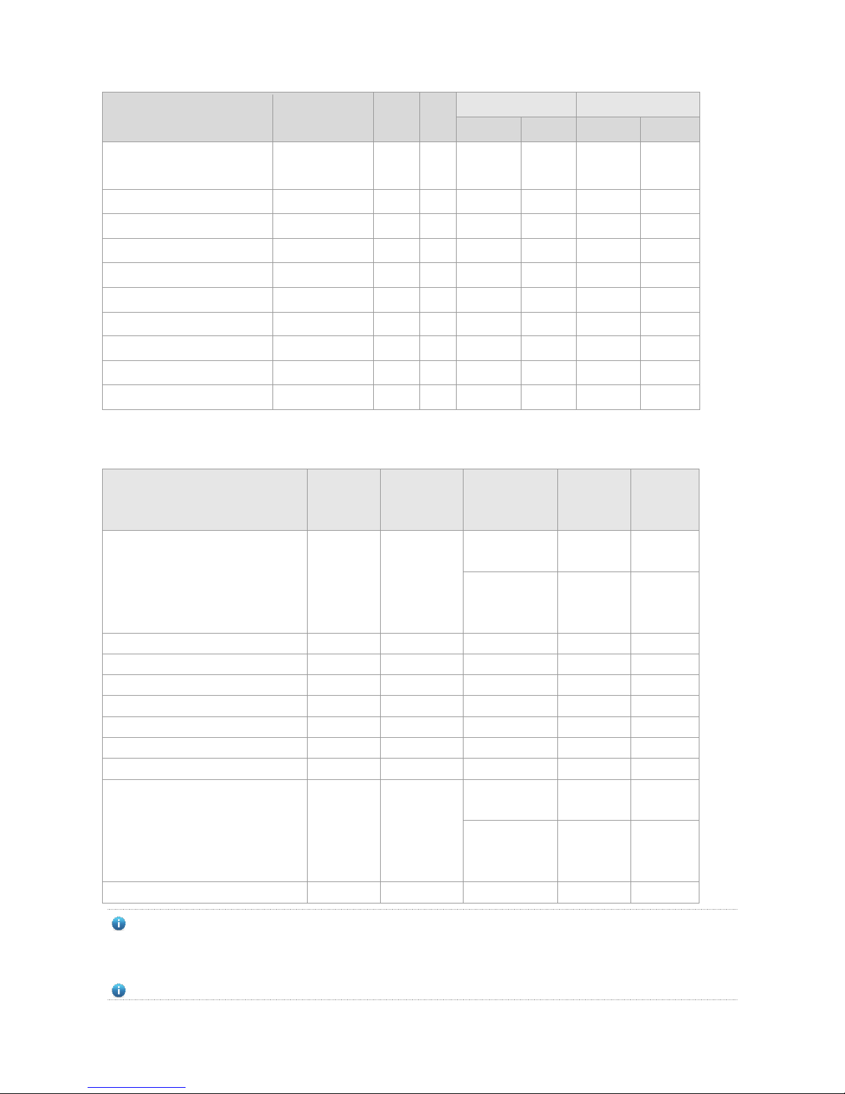
Table B-1 Models and Technical Specifications of the 1000M Mini-GBIC(SFP) Module
Model
Wave Length
(nm)
Media
Type
DDM
(Yes/
No)
Intensity of
Transmitted Light
(dBm)
Intensity of Received
Light (dBm)
Min
Max
Min
Max
MINI-GBIC-SX-MM850
850
MMF
No
-9.5
-3
-17
0
MINI-GBIC-LX-SM1310
1310
SMF
No
-9.5
-3
-20
-3
GE-SFP-SX
850
MMF
No
-9.5
-3
-17 0 GE-SFP-LX
1310
SMF
No
-9.5
-3
-20
-3
GE-SFP-SX-SM1550-BIDI
1550TX/1310RX
MMF
No
-10
-5
-17
-3
GE-SFP-SX-SM1310-BIDI
1310TX/1550RX
MMF
No
-10
-5
-17
-3
GE-eSFP-SX-MM850
850
MMF
Yes
-9.5
-3
-17 0 GE-eSFP-LX-SM1310
1310
SMF
Yes
-9.5
-3
-20
-3
GE-SFP-LX-SM1310
1310
SMF
No
-9.5
-3
-20
-3
GE-SFP-LX20-SM1310-BIDI
1310TX/1550RX
SMF
Yes
-9
-3
-20
-3
GE-SFP-LX20-SM1550-BIDI
1550TX/1310RX
SMF
Yes
-9
-3
-20
-3
GE-SFP-LH40-SM1310-BIDI
1310TX/1550RX
SMF
Yes
-5 0 -24
-1
GE-SFP-LH40-SM1550-BIDI
1550TX/1310RX
SMF
Yes
-5 0 -24
-1
MINI-GBIC-LH40-SM1310
1310
SMF
Yes
-2 3 -22
-3
MINI-GBIC-ZX50-SM1550
1550
SMF
Yes
-5 0 -22
-3
MINI-GBIC-ZX80-SM1550
1550
SMF
Yes 0 4.7
-22
-3
MINI-GBIC-ZX100-SM1550
1550
SMF
Yes 0 5
-30
-9
Table B-2 Models of 1000M SFP Copper Module
Standard
Model
DDM (Yes/No)
1000Base-T
Mini-GBIC-GT
No
Table B-3 Module Cabling Specification
Model
Interface
Type
Fiber Type
Core Size(μm)
Cable Distance (Max.)
MINI-GBIC-SX-MM850
LC
MMF
62.5/125
275m

50/125
550m
MINI-GBIC-LX-SM1310
LC
SMF
9/125
10km
GE-eSFP-SX-MM850
LC
MMF
62.5/125
275m
50/125
550m
GE-eSFP-LX-SM1310
LC
SMF
9/125
10km
GE-SFP-LX-SM1310
LC
SMF
9/125
10km
MINI-GBIC-LH40-SM1310
LC
SMF
9/125
40km
GE-SFP-SX-SM1310-BIDI
LC
MMF
50/125
500m
GE-SFP-SX-SM1550-BIDI
LC
MMF
50/125
500m
GE-SFP-LX20-SM1310-BIDI
LC
SMF
9/125
20km
GE-SFP-LX20-SM1550-BIDI
LC
SMF
9/125
20km
GE-SFP-LH40-SM1310-BIDI
LC
SMF
9/125
40km
GE-SFP-LH40-SM1550-BIDI
LC
SMF
9/125
40km
MINI-GBIC-ZX50-SM1550
LC
SMF
9/125
50km
MINI-GBIC-ZX80-SM1550
LC
SMF
9/125
80km
MINI-GBIC-ZX100-SM1550
LC
SMF
9/125
100km
SDH155-SFP-SX-MM850
LC
MMF
62.5/125
500m
SDH155-SFP-SX-MM1310
LC
MMF
62.5/125
2km
SDH155-SFP-LH15-SM1310
LC
SMF
9/125
15km
SDH155-SFP-LH40-SM1310
LC
SMF
9/125
40km
SDH155-SFP-LH80-SM1310
LC
SMF
9/125
80km
GE-SFP-SX
LC
MMF
62.5/125
275m
50/125
550m
GE-SFP-LX
LC
SMF
9/125
10km
Mini-GBIC-GT
RJ45
Category 5 (or above ) UTP or STP
100m
For the optical module with transmission distance exceeding 40 km and more, one on-line optical attenuator should
be added on the link to avoid the overload of the optical receiver when short single-mode optical fibers are used.
Optical modules generate laser. Do not stare at light source.
To keep optical modules clean, please use dust caps when the modules are not connected with fibers.
Table B-4 Models and Technical Specifications of 2.5G SFP Cable Module
Model
Module Type
Connector
Length(m)
Data Rate(Gb/s)
Support DDM
(Yes/No)
GE-SFP-STACK1.6M
Passive
SFP
1.6
3.125
No
No extra cables are needed when SFP cables are used. Inserting the two ends of a SFP cable into corresponding
ports facilitates inter-communication between the two ports.
Table B-5 Models and Specifications of 10G SFP+ Modules
Model
Wave Length
(nm)
Media
Type
DDM
(Yes/
Intensity of
Transmitted Light
Intensity of Received
Light (dBm)
No)
(dBm)
Min
Max
Min
Max
XG-SFP-SR-MM850
850
MMF
Yes
-5
-1
-7.5
0.5
XG-SFP-SR-SM1270-BIDI
1270
MMF
No
-3 4 -9
0.5
XG-SFP-SR-SM1330-BIDI
1270
MMF
No
-3 4 -9
0.5
XG-SFP-LR-SM1270-BIDI
1270
SMF
No
-6.5
0.5
-14.4
0.5
XG-SFP-LR-SM1330-BIDI
1330
SMF
No
-6.5
0.5
-14.4
0.5
XG-SFP-LR-SM1310
1310
SMF
Yes
-8.2
0.5
-14.4
0.5
XG-SFP-ER-SM1550
1550
SMF
Yes
-4.7 4 -11.3
-1
XG-SFP-ZR-SM1550
1550
SMF
Yes 0 4
-24
-7
XS-SFP-SR
850
MMF
Yes
-5
-1
-7.5
0.5
XS-SFP-LR
1310
SMF
Yes
-8.2
0.5
-10.3
0.5
Table B-6 SFP+ Module Cabling Specification
Model
Interface
Type
Fiber Type
Core Size(μm)
Modular
Bandwidth
(MHz/km)
Cable
Distance
(Max.)
XG-SFP-SR-MM850
LC
MMF
62.5/125
200(OM1)
160
33m
26m
50/125
2000(OM3)
500(OM2)
400(OM1)
300m
82m
66m
XG-SFP-SR-SM1270-BIDI
LC
MMF
50/125
2000(OM3)
300m
XG-SFP-SR-SM1330-BIDI
LC
MMF
50/125
2000(OM3)
300m
XG-SFP-LR-SM1270-BIDI
LC
SMF
9/125
N/A
10km
XG-SFP-LR-SM1330-BIDI
LC
SMF
9/125
N/A
10km
XG-SFP-LR-SM1310
LC
SMF
9/125
N/A
10km
XG-SFP-ER-SM1550
LC
SMF
9/125
N/A
40km
XG-SFP-ZR-SM1550
LC
SMF
9/125
N/A
80km
XS-SFP-SR
LC
MMF
62.5 /125
200(OM1)
160
33m
26m
50/125
2000(OM3)
500(OM2)
400(OM1)
300m
82m
66m
XS-SFP-LR
LC
SMF
9/125
N/A
10km
For XG-SFP-ER-SM1550 and XG-SFP-ZR-SM1550, please do not use short-distance fibers for connection to avoid
the overload of the transceiver. If optical power on the receiving end is not lower than -1dBm, a proper optical
attenuator is supposed to be installed onto the end so as to reduce the optical power to lower than -1dBM.
Optical modules generate laser. Do not stare at light source.

To keep optical modules clean, please use dust caps when the modules are not connected with fibers.
Table B-7 Models and Specifications of Existing 10G SFP+ Cable Modules
Model
Module
Type
Connector
Length(m)
Conductor Wire
Diameter (AWG)
Data Rate(Gb/s)
Support
DDM
(Yes/No)
XG-SFP-CU1M
Passive
SFP+
1
28
10.3125
No
XG-SFP-CU3M
Passive
SFP+
3
28
10.3125
No
XG-SFP-CU5M
Passive
SFP+
5
26
10.3125
No
XG-SFP-AOC1M
Active
SFP+
1 \ 10.3125
No
XG-SFP-AOC3M
Active
SFP+
3 \ 10.3125
No
XG-SFP-AOC5M
Active
SFP+
5 \ 10.3125
No
No extra cables are needed when SFP cables are used. Inserting the two ends of a SFP cable into corresponding
ports facilitates inter-communication between the two ports.
Table B-8 Specifications of SFP BIDI Optical Module Pairs
Rate/Distance
Module Pairs
1000M/500m
GE-SFP-SX-SM1310-BIDI
GE-SFP-SX-SM1550-BIDI
1000M /20km
GE-SFP-LX20-SM1310-BIDI
GE-SFP-LX20-SM1550-BIDI
100M/40km
GE-SFP-LH40-SM1310-BIDI
GE-SFP-LH40-SM1550-BIDI
10G /300m
XG-SFP-SR-SM1270-BIDI
XG-SFP-SR-SM1330-BIDI
10G /10km
XG-SFP-LR-SM1270-BIDI
XG-SFP-LR-SM1330-BIDI
The BIDI modules must be used in pairs (e.g., FE-SFP-LX20-SM1310-BIDI and FE-SFP-LX20-SM1550-BIDI).

Appendix C Lightning Protection
Installing AC Power Arrester (lightning protection cable row)
The external lightning protection cable row shall be used on the AC power port to prevent the switch from being struck by
lightning when the AC power cable is introduced from the outdoor and directly connected to the power port of the switch.
The lightning protection cable row is fixed on the cabinet, operating table or the wall in the machine room using the line
buttons and screws.
Figure C-1 Schematic Diagram for the Power Arrester
The power arrester is not provided and the user shall purchase it to address the practical requirement.
Precautions for installation:
Make sure that the PE terminal of the power arrester has been well-grounded;
After connecting the switch AC power plug to the socket of the power arrester (lightning protection cable row),
lightning protection function implements if the RUN LED is Green and the ALARM LED is OFF.
If the ALARM LED on the power arrester is Red, you shall check what the reason is, poor grounding connection or
the reversed connection of the Null and Live lines: Use the multimeter to check the polarity of the power socket for
the arrester when the LED is Red, if the N line is on the left and the L line is on the right, the arrester PE terminal is
not grounded; if the L line is on the left and the N line is on the right, the polarity of the arrester power cable shall be
reversed; if the LED is still Red, it is confirmed that the arrester PE terminal has not been grounded.
Installing the Ethernet Port Arrester

During the switch usage, the Ethernet port arrester shall be connected to the switch to prevent the switch damage by
lightning before the outdoor network cable connects to the switch.
Tools: Cross or straight screwdriver, Multimeter, Diagonal pliers
Installation Steps:
1. Tear one side of the protection paper for the double-sided adhesive tape and paste the tape to the framework of the
Ethernet port arrester. Tear the other side of the protection paper for the double-sided adhesive tape and paste the
Ethernet port arrester to the switch framework. The paste location for the Ethernet port arrester shall be as close to
the grounding terminal of the switch.
2. Based on the distance of the switch grounding terminal, cut the grounding line for the Ethernet port arrester and firmly
tighten the grounding line to the grounding terminal of the switch.
3. Use the multimeter to check whether the grounding line for the arrester is in good contact with the switch grounding
terminal and the framework.
4. According to the description on the Ethernet Port Arrester Hardware Installation Guide, connect the arrester using the
adapter cable(note that the external network cable is connected to the end of IN, while the adapter cable connected to the
switch is connected to the end of OUT) and observe whether the LED on the board is normal or not.
5. Use the nylon button to bundle the power cables.
Figure C-2 Schematic Diagram for the Ethernet port Arrester Installation
The Ethernet port arrester is only for the 10M/100M copper Ethernet ports with the RJ-45 connector;
The Ethernet port arrester is not provided, the user can purchase them to address their own practical requirements.
For the detailed information during the arrester installation, please refer to Ethernet Port Arrester Hardware
Installation Guide, which contains the technical specification and the maintenance and installation of the arrester.
You may pay attention to the following conditions during the actual installation to avoid influencing the performance of the
Ethernet port arrester:

Reversed direction of the arrester installation. You shall connect the external network cable to the “IN” end and
connect the switch Ethernet port to the “OUT” end.
Poor arrester grounding. The length of the grounding line should be as short as possible to ensure that it is in good
contact with the switch grounding terminal. Use the multimeter to confirm the contact condition after the grounding.
Incomplete arrester installation. If there is more than one port connected to the peer device on the switch, it needs to
install the arresters on all connection ports for the purpose of the lightning protection.

Appendix D Cabling Recommendations in Installation
When RG-S2910-H series switches are installed in standard 19-inch cabinets, the cables are tied in the binding rack on
the cabinet by the cabling rack, and top cabling or bottom cabling is adopted according to the actual situation in the
equipment room. All cable connectors should be placed at the bottom of the cabinet in an orderly manner instead of
outside the cabinet easy to touch. Power cables are routed beside the cabinet, and top cabling or bottom cabling is
adopted according to the actual situation in the equipment room, such as the position of the DC power distribution box, AC
socket, or lightning protection box.
Requirement for the minimum cable bend radius
The bend radius of a power cord, communication cable, and flat cable should be greater than five times their
respective diameters. The bend radius of these cables that often bend or suffer removal/insertion should be greater
than seven times their respective diameters.
The bend radius of a common coaxial cable should be greater than seven times its diameter. The bend radius of this
type of cables that often bend or suffer removal/insertion should be greater than 10 times its diameter.
The bend radius of a high-speed cable (SFP cable, for example) should be greater than five times its diameter. The
bend radius of this type of cables that often bend or suffer removal/insertion should be greater than 10 times its
diameter.
Requirement for the minimum fiber bend radius
The diameter of a fiber tray to hold fibers cannot be less than 25 times the diameter of the fiber.
When moving an optical fiber, the bend radius of the fiber should be equal to or greater than 20 times the diameter of
the fiber.
During cabling of an optical fiber, the bend radius of the fiber should be equal to or greater than 10 times the
diameter of the fiber.
Precautions for Bundling up Cables
Before bundling cables, correctly mark labels and stick the labels to cables where appropriate.
Cables should be neatly and properly bundled, as shown in Figure D-1.
Figure D-1 Bundling Up Cables (1)

Cables of different types (such as power cords, signal cables, and grounding cables) should be separated in cabling
and bundling. When they are close, crossover cabling can be adopted. In the case of parallel cabling, power cords
and signal cables should maintain a space equal to or greater than 30 mm.
The binding rack and cabling slot inside and outside the cabinet should be smooth, without sharp corners.
The metal hole traversed by cables should have a smooth and fully rounding surface or an insulated lining.
Proper buckles should be selected to bundle up cables. It is forbidden to connect two or more buckles to bundle up
cables.
After bundling up cables with buckles, you should cut off the remaining part. The cut should be smooth and trim,
without sharp corners, as shown in Figure D-2.
Figure D-2 Bundling Up Cables (2)
When cables need to bend, you should first bundle them up. However, the buckle cannot be bundled within the bend
area. Otherwise, significant stress may be generated in cables, breaking cable cores. As shown in Figure D-3.

Figure D-3 Bundling Up Cables (3)
Cables not to be assembled or remaining parts of cables should be folded and placed in a proper position of the
cabinet or cabling slot. The proper position indicates a position that will not affect device running or cause device
damage or cable damage during commissioning.
The power cords cannot be bundled on the guide rails of moving parts.
The power cables connecting moving parts such as door grounding wires should be reserved with some access after
assembled. When the moving part reaches the installation position, the remaining part should not touch heat sources,
sharp corners, or sharp edges. If heat sources cannot be avoided, high-temperature cables should be used.
When using screw threads to fasten cable terminals, the bolt or screw must be tightly fastened, and anti-loosening
measures should be taken, as shown in Figure D-4.
Figure D-4 Cable Fastening

The hard power cable should be fastened by the terminal connection area to prevent stress.
Do not use self-tapping screws to fasten terminals.
Power cables of the same type and in the same cabling direction should be bundled up into cable bunches, with
cables in cable bunches clean and straight.
Binding by using buckles should be performed according to Table D-1.
Cable Bunch Diameter (mm)
Binding Space (mm)
10
80-150
10-30
150-200
30
200-300
No knot is allowed in cabling or bundling.
For solder-less terminal blocks (such as air switches) of the cold pressing terminal type, the metal part of the cold
pressing terminal should not be exposed outside the terminal block when assembled

Appendix E Site Selection
The machine room should be at least 5km away from the heavy pollution source such as the smelter, coal mine and
thermal power plant, 3.7km away from the medium pollution source such as the chemical industry, rubber industry
and electroplating industry, and 2km away from the light pollution source such as the food manufacturer and leather
plant. If the pollution source is unavoidable, the machine room should be located on the windward side of the
pollution source perennially with advanced protection.
The machine room should be at least 3.7km away from the sea or salt lake. Otherwise, the machine room must be
sealed, with air conditioner installed for temperature control. Saline soil cannot be used for construction. Otherwise,
you should select devices with advanced protection against severe environment.
Do not build the machine room in the proximity of livestock farms. Otherwise, the machine room should be located
on the windward side of the pollution source perennially. The previous livestock house or fertilizer warehouse cannot
be used as the machine room.
The machine room should be firm enough to withstand severe weather conditions such as windstorm and heavy rain
as well as away from dust. If the dust is unavoidable, keep the door and window away from the pollution source.
The machine room should be away from the residential area. Otherwise, the machine room should meet the
construction standard in terms of noise.
Make sure the air vent of the machine room is away from the sewage pipe, septic tank, and sewage treatment tank.
Keep the machine room under positive pressure to prevent corrosive gas from entering the machine room to corrode
components and circuit boards. Keep the machine room away from industrial boiler and heating boiler.
The machine room had better be on the second floor or above. Otherwise, the machine room floor should be 600mm
higher than the highest flood level ever recorded.
Make sure there are no cracks or holes in the wall and floor. If there are cable entries in the wall or window, take
proper sealing measures. Ensure that the wall is flat, wear-resistant, and dust-free, which should be up to the
standard for flame retarding, soundproofing, heat absorption, dust reduction, and electromagnetic shielding.
Keep the door and the window closed to make the machine room sealed.
The steel door is recommended for soundproofing.
Sulfur-containing materials are forbidden.
Pay attention to the location of the air conditioner. Keep the air conditioner from blowing wind straight toward the
device or blowing water drops from the window or air vent toward the device.
 Loading...