

Ruijie RG-S1808, RG-S1818G, RG-S1826G, RG-S1809-P, RG-S1826 Hardware Installation And Reference Manual
...
Hardware Installation and Reference Guide
RG-S1800 Series Switch
RG-S1800G Series Switch
RG-S1800-P Series Switch
RG-S1800G-P Series Switch

Copyright Statement
Ruijie Networks©2017
Ruijie Networks reserves all copyrights of this document. Any reproduction, excerption, backup, modification,
transmission, translation or commercial use of this document or any portion of this document, in any form or by any
means, without the prior written consent of Ruijie Networks is prohibited.
Exemption Statement
This document is provided “as is”. The contents of this document are subject to change without any notice. Please
obtain the latest information through the Ruijie Networks website. Ruijie Networks endeavors to ensure content
accuracy and will not shoulder any responsibility for losses and damages caused due to content omissions,
inaccuracies or errors.

Preface
Thank you for using our products. This manual will guide you through the installation of the device.
This manual describes the functional and physical features and provides the device installation steps, hardware
troubleshooting, module technical specifications, and specifications and usage guidelines for cables and connectors.
Audience
It is intended for the users who have some experience in installing and maintaining network hardware. At the same time,
it is assumed that the users are already familiar with the related terms and concepts.
Obtaining Technical Assistance
Ruijie Networks Website: http://www.ruijienetworks.com/
Service Email: service_rj@ruijienetworks.com
Technical Support: http://www.ruijienetworks.com/service.aspx
Technical Support Hotline: +86-4008-111-000
Symbol Conventions
Means reader take note. Notes contain helpful suggestions or references.
Means reader be careful. In this situation, you might do something that could result in equipment damage or loss
of data.

Hardware Installation and Reference Guide Product Overview
Table of Contents
1 Product Overview................................................................................................................................................... - 6 -
1.1 RG-S1800 Series Switch....................................................................................................................... - 7 -
1.1.1 RG-S1808 ..................................................................................................................................... - 7 -
1.1.2 RG-S1826 ..................................................................................................................................... - 9 -
1.2 RG-S1800G Series Switch .................................................................................................................. - 11 -
1.2.1 RG-S1808G ................................................................................................................................ - 11 -
1.2.2 RG-S1818G ................................................................................................................................ - 14 -
1.2.3 RG-S1826G ................................................................................................................................ - 16 -
1.2.4 Module ........................................................................................................................................ - 19 -
1.3 RG-S1800-P Series Switch ................................................................................................................. - 19 -
1.3.1 RG-S1809-P ............................................................................................................................... - 19 -
1.4 RG-S1800G-P Series Switch .............................................................................................................. - 21 -
1.4.1 RG-S1826G-P ............................................................................................................................ - 21 -
1.4.2 Module ........................................................................................................................................ - 24 -
2 Preparation before Installation ............................................................................................................................. - 25 -
2.1 Safety Suggestions ............................................................................................................................. - 25 -
2.1.1 Safety Precautions for Installing the System ............................................................................... - 25 -
2.1.2 Movement Safety ........................................................................................................................ - 25 -
2.1.3 Electric Safety ............................................................................................................................. - 25 -
2.1.4 Static Discharge Damage Prevention ......................................................................................... - 26 -
2.1.5 Laser Safety ................................................................................................................................ - 26 -
2.2 Installation Site Requirements ............................................................................................................. - 26 -
2.2.1 Ventilation Requirements ............................................................................................................ - 26 -
2.2.2 Temperature and Humidity Requirements .................................................................................. - 26 -
2.2.3 Cleanness Requirements ............................................................................................................ - 27 -
2.2.4 EMI ............................................................................................................................................. - 27 -
2.2.5 System Grounding Requirements ............................................................................................... - 28 -
2.2.6 Lightning Resistance Considerations .......................................................................................... - 29 -
2.2.7 EMI Consideration ...................................................................................................................... - 30 -
2.3 Requirements of Installation Tools ...................................................................................................... - 30 -
3 Product Installation .............................................................................................................................................. - 31 -
3.1 Installation Procedure.......................................................................................................................... - 31 -
3.2 Confirmations before Installation ......................................................................................................... - 31 -
3.3 Precautions ................................................................................................................................ ......... - 31 -
3.4 Installing the RG-S1800 Series ........................................................................................................... - 32 -
3.4.1 Mounting the Switch in the Rack ................................................................................................. - 32 -
3.4.2 Mounting the Switch on the Wall ................................................................................................. - 33 -
3.4.3 Mounting the Switch to a Workbench ................................................................ .......................... - 34 -
3.5 Installing the RG-S1800G Series ........................................................................................................ - 34 -
3.5.1 Mounting the Switch in the Rack ................................................................................................. - 34 -
3.5.2 Mounting the Switch on the Wall ................................................................................................. - 35 -

Hardware Installation and Reference Guide Product Overview
3.5.3 Mounting the Switch to a Workbench ................................................................ .......................... - 36 -
3.6 Installing the RG-S1800-P Series ....................................................................................................... - 37 -
3.6.1 Mounting the Switch to a Workbench ................................................................ .......................... - 37 -
3.6.2 Mounting the Switch on the Wall ................................................................................................. - 38 -
3.7 Installing the RG-S1800G-P Series ..................................................................................................... - 40 -
3.7.1 Mounting the Switch in the Rack ................................................................................................. - 40 -
3.7.2 Mounting the Switch on the Wall ................................................................................................. - 40 -
3.7.3 Mounting the Switch to a Workbench ................................................................ .......................... - 41 -
3.8 Connecting the Power Cord ................................................................................................................ - 42 -
3.9 Checking after Installation ................................................................................................................... - 43 -
4 Maintenance and Troubleshooting ....................................................................................................................... - 44 -
4.1 General Troubleshooting Procedure ................................................................................................... - 44 -
4.2 Common Faults ................................................................................................................................... - 44 -
Appendix A: Connectors and Connection Media .............................................................................................................. 46
Appendix B Mini-GBIC Modules ................................................................................................................................... - 48 -

Hardware Installation and Reference Guide Product Overview
1 Product Overview
Thank you for using Ruijie Networks RG-S18 series Ethernet switches.
The RG-S1800 series switches are unmanaged 100M switches released by Ruijie Networks. Some of the switches
provide GE uplink ports, powerful switching performance, and cost-effective GE port-based uplink capability.
The RG-S1800G series switches are full GE switches released by Ruijie Networks. With powerful switching capability
and cost-effective full GE copper cable ports, the switches fully meet users' requirements for high-bandwidth data
communication, dense high-speed access server clusters, and GE backbone service network construction.
The RG-S1800-P series switches are PoE-capable 100M Ethernet switches released by Ruijie Networks. Some of the
switches provide 100M uplink ports, powerful switching performance, and cost-effective 100M port-based uplink
capability. In addition, some other switches provide GE uplink ports, powerful switching performance, and cost-effective
GE port-based uplink capability. This series of switches are characterized by high performance, high security, support
for multiple services, and ease of use, and provide brand new technical solutions for users. Each port of the switches
can provide high bandwidth and supply power to wireless APs and IP cameras. The switches support full-/half-duplex
mode, and enable low-cost and high-performance network solutions.
The RG-S1800G-P series switches are full GE PoE switches released by Ruijie Networks. The switches are
characterized by high performance, high security, support for multiple services, and ease of use, and enable new
technical solutions for users. Each port of the switches can provide high bandwidth and supply power to wireless APs
and IP cameras. The switches support full-/half-duplex mode, and enable low-cost and high-performance network
solutions.
Some models of the S18 series switches are capable of independent flow control, which prevents data packet loss
during data transmission.
RG-S1800 Series Switch
Model
10/100BASE-T
Auto-sensing Ethernet
Port
Combo Ports
10/100/1000BASE-T
Auto-sensing Ethernet
Port
1000BASE-X SFP Port
RG-S1808
8
N/A
N/A
RG-S1826
24 2 2
Combo port consists of one 1000BASE-X SFP port and one 10/100/1000BASE-T auto-sensing Ethernet port. That
is, only one port of them is available at a particular time.
RG-S1800G Series Switch
Model
10/100/1000BASE-T Auto-sensing Ethernet
Port
1000BASE-X SFP Port
RG-S1808G
8
N/A
RG-S1818G
16
2

Hardware Installation and Reference Guide Product Overview
RG-S1826G
24
2
RG-S1800-P Series Switch
Model
10/100BASE-T Auto-sensing
Ethernet Port
10/100/1000BASE-T
Auto-sensing Ethernet Port
PoE Port
RG-S1809-P
8 1 8
RG-S1800G-P Series Switch
Model
10/100/1000BASE-T
Auto-sensing Ethernet Port
PoE Port
1000BASE -X SFP Port
RG-S1826G-P
24
24
2
1.1 RG-S1800 Series Switch
1.1.1 RG-S1808
Technical Specifications
Model
RG-S1808
Ports
8-port 10/100BASE-T
Power Supply
DC input:
DC 5V/550mA
Rated current: 550mA
Max voltage range: 90V to 290V~
PoE
Not supported
Power Consumption
1.5W(Max)
Operating
Temperature
0ºC to 50ºC (32ºF to 122ºF)
Storage Temperature
-40ºC to +70ºC (-40ºF to 158ºF)
Operating Humidity
10% to 90% RH non-condensing
Storage Humidity
5% to 90% RH non-condensing
Fan
N/A
EMC Standards
EN55032(Class B)
Dimensions (W×D×H)
140 mm x 76 mm x 27 mm
Switching
Capacity(Gbps)
1.6Gbps
Product Appearance
The front panel of RG-S1808 Ethernet switch provides a Power Status LED indicator and Link/ACT Status LED
indicators. The rear panel provides eight 10/100BASE-T Ethernet ports and one DC power input port. Figure 1-1 shows
the appearance of the RG-S1808.
Figure 1-1 Appearance of RG-S1808

Hardware Installation and Reference Guide Product Overview
Front Panel
Figure 1-2 Front Panel of RG-S1808
Note
1. Power status indicator
2. 10/100BASE-T Link/ACT indicator
Rear Panel
Figure1-3 Rear Panel of RG-S1808
Note
1. 10/100BASE-T ports
2. DC power input port
Power Supply
The RG-S1808 switch can be powered with DC power.
DC input: DC 5V/550mA
Heat Dissipation

Hardware Installation and Reference Guide Product Overview
The RG-S1808 switch is designed with no fans. To ensure good dissipation, sufficient space (10 cm distance from both
sides and the back panel of the chassis) should be reserved for ventilation. Dust the device every three months to avoid
blocking the ventilation openings.
LED Indicator
Indicator
Faceplate Marker
Status
Indication
Power indicator
PWR
Off
The switch is powered down.
On
The switch is powered on.
Ethernet port indicator
1-8
Off
The port is NOT connected.
Solid green
The port is connected.
Blinking green
The port is transmitting or receiving data.
1.1.2 RG-S1826
Technical Specifications
Model
RG-S1826
Ports
24-port 10/100BASE-T
2 combo ports
SFP Type
Ethernet Gigabit:
Mini-GBIC-SX
Mini-GBIC-LX
Mini-GBIC-LH40
Mini-GBIC-ZX50
Mini-GBIC-ZX80
Mini-GBIC-ZX100
1000Base-T:
Mini-GBIC-GT
The supported module type may change at any time. Consult us for the detailed change
information.
SFP Ports
Support 1000BASE-X
Power Supply
AC input:
Rated voltage range: 100V to 240V
Max voltage range: 90V to 290V
Frequency: 50/60Hz
Rated current: 0.5A
PoE
Not supported

Hardware Installation and Reference Guide Product Overview
Power Consumption
12W(Max)
Operating
Temperature
0ºC to 50ºC (32ºF to 122ºF)
Storage Temperature
-40ºC to +70ºC (-40ºF to 158ºF)
Operating Humidity
10% to 90% RH non-condensing
Storage Humidity
5% to 90% RH non-condensing
Fan
N/A
EMC Standards
EN55032(Class A)
Dimensions (W×D×H)
440 mm x 205 mm x 44 mm
Switching Capacity
8.8Gbps
Product Appearance
The front panel of RG-S1826 Ethernet switch provides 24 10/100BASE-T Ethernet ports, two Gigabit combo ports. The
rear panel provides an AC power input port and a grounding connector.
Figure 1-4 Appearance of RG-S1826
Front Panel
Figure 1-5 Front Panel of RG-S1826
Note
1. Power status indicator
2. 10/100BASE-T Link/ACT indicator
3.10/100/1000BASE-T Link/ACT
indicator
4. 10/100BASE-T Ethernet port
5. 10/100/1000BASE-T Ethernet port
6. 1000BASE-X SFP port
Rear Panel
Figure1-6 Rear Panel of RG-S1826
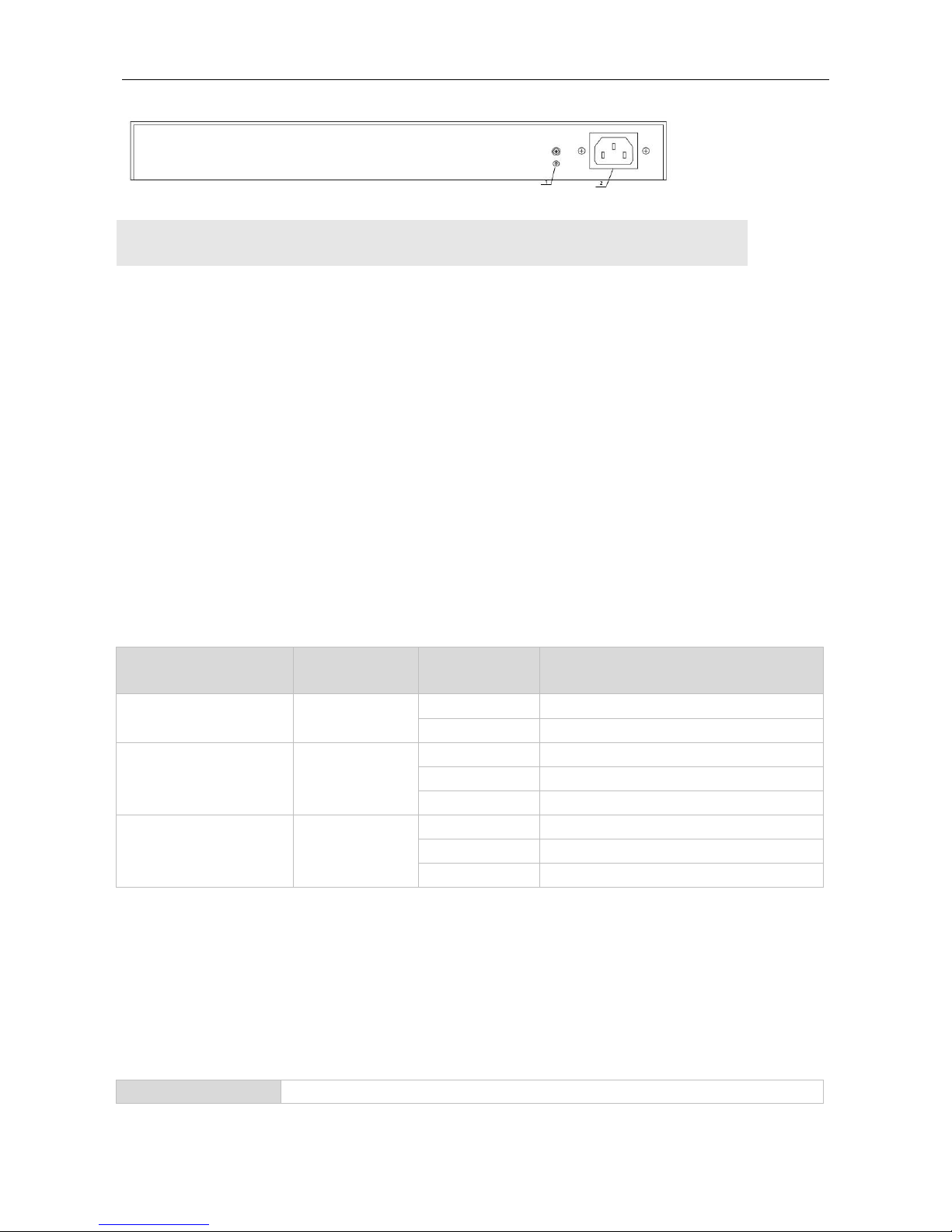
Hardware Installation and Reference Guide Product Overview
Note
1. Grounding connector
2. AC power input port
Power Supply
The RG-S1826 switch can be powered with AC power.
Rated voltage range: 100V to 240V
Max voltage range: 90V to 290V
Frequency: 50/60Hz
Rated current: 0.5A
Power Cord Requirements: 10A
Heat Dissipation
The RG-S1826 switch is designed with no fans. To ensure good dissipation, sufficient space (10 cm distance from both
sides and the back panel of the chassis) should be reserved for ventilation. Dust the device every three months to avoid
blocking the ventilation openings.
LED Indicator
Indicator
Faceplate Marker
Status
Indication
Power indicator
PWR
Off
The switch is powered down.
On
The switch is powered on.
Ethernet port indicator
1-24
Off
The port is NOT connected.
Solid green
The port is connected.
Blinking green
The port is transmitting or receiving data.
Combo port indicator
25 T/S
26 T/S
Off
The port is NOT connected.
Solid green
The port is connected.
Blinking green
The port is transmitting or receiving data.
1.2 RG-S1800G Series Switch
1.2.1 RG-S1808G
Technical Specifications
Model
RG-S1808G

Hardware Installation and Reference Guide Product Overview
Ports
8-port 10/100/1000 BASE-T
Power Supply
AC input:
Rated voltage range: 100V to 240V
Max voltage range: 90V to 290V
Frequency: 50/60Hz
Rated current: 0.3A
PoE
Not supported
Power Consumption
2.5W(Max)
Operating Temperature
0ºC to 50ºC (32ºF to 122ºF)
Storage Temperature
-40ºC to +70ºC (-40ºF to 158ºF)
Operating Humidity
10% to 90% RH non-condensing
Storage Humidity
5% to 90% RH non-condensing
Fan
N/A
EMC Standards
EN55032(Class B)
Dimensions (W×D×H)
220 mm x 160 mm x 44 mm
Switching
Capacity(Gbps)
16Gbps
Product Appearance
The front panel of RG-S1808G Ethernet switch provides eight 10/100/1000Mbps Ethernet ports. The rear panel
provides an AC power input port and a grounding connector.
Figure 1-7 Appearance of RG-S1808G
Front Panel
Figure 1-8 Front Panel of RG-S1808G

Hardware Installation and Reference Guide Product Overview
Note
1. Power status indicator
2. 10/100/1000BASE-T Link/ACT/Speed
indicator
3. Power cord retention clip
Rear Panel
Figure1-9 Rear Panel of RG-S1808G
Note
1. Grounding connector
2. AC power input port
Power Supply
The RG-S1808G switch can be powered with AC power.
Rated voltage range: 100V to 240V
Max voltage range: 90V to 290V
Frequency: 50/60Hz
Rated current: 0.3A
Power cord requirement: 10A
Heat Dissipation
The RG-S1808G switch is designed with no fans. To ensure good dissipation, sufficient space (10 cm distance from
both sides and the back panel of the chassis) should be reserved for ventilation. Dust the device every three months to
avoid blocking the ventilation openings.
LED Indicator
Indicator
Faceplate
Marker
Status
Indication
Power indicator
PWR
Off
The switch is powered down.
On
The switch is powered on.
Ethernet port indicator
1-8
Off
The port is NOT connected.
Solid orange
The port is connected at 10/100 Mbps.

Hardware Installation and Reference Guide Product Overview
Blinking orange
The port is receiving or transmitting
traffic at 10/100 Mbps.
Solid green
The port is connected at 1000 Mbps.
Blinking green
The port is receiving or transmitting
traffic at 1000 Mbps.
1.2.2 RG-S1818G
Technical Specifications
Model
RG-S1818G
Ports
16-port 10/100/1000BASE-T
2-port 1000BASE-X SFP
SFP Type
Ethernet Gigabit:
Mini-GBIC-SX
Mini-GBIC-LX
Mini-GBIC-LH40
Mini-GBIC-ZX50
Mini-GBIC-ZX80
Mini-GBIC-ZX100
1000Base-T:
Mini-GBIC-GT
The supported module type may change at any time. Consult us for the detailed
change information.
SFP Ports
Support 1000Base-X
Power Supply
AC input:
Rated voltage range: 100V to 240V
Max voltage range: 90V to 290V
Frequency: 50/60Hz
Rated current: 0.5A
PoE
Not supported
Power Consumption
9W(max)
Operating
Temperature
0ºC to 50ºC (32ºF to 122ºF)
Storage Temperature
-40ºC to +70ºC (-40ºF to 158ºF)
Operating Humidity
10% to 90% RH non-condensing
Storage Humidity
5% to 90% RH non-condensing
Fan
N/A
EMC Standards
EN55032(Class A)
Dimensions (W×D×H)
440 mm x 205 mm x 44 mm

Hardware Installation and Reference Guide Product Overview
Switching
Capacity(Gbps)
36Gbps
Product Appearance
The front panel of RG-S1818G Ethernet switch provides 16 10/100/1000BASE-T Ethernet ports, two 1000BASE-X SFP
ports. The rear panel provides an AC power input port and a grounding connector.
Figure 1-10 Appearance of RG-S1818G
Front Panel
Figure 1-11 Front Panel of RG-S1818G
Note
1. Power status indicator
2. 10/100/1000BASE-T Link/ACT/Speed
indicator
3.1000BASE-X SFP port indicator
4. 10/100/1000BASE-T Ethernet port
5. 1000BASE-X SFP port
Rear Panel
Figure1-12 Rear Panel of RG-S1818G
Note
1. Grounding connector
2. AC power input port
Power Supply

Hardware Installation and Reference Guide Product Overview
RG-S1818G switch can be powered with AC power.
Rated voltage range: 100V to 240V
Max voltage range: 90V to 290V
Frequency: 50/60Hz
Rated current: 0.5A
Power cord requirement: 10A
Heat Dissipation
The RG-S1818G switch is designed with no fans. To ensure good dissipation, sufficient space (10 cm distance from
both sides and the back panel of the chassis) should be reserved for ventilation. Dust the device every three months to
avoid blocking the ventilation openings.
LED Indicator
Indicator
Faceplate
Marker
Status
Indication
Power indicator
PWR
Off
The switch is powered down.
On
The switch is powered on.
Ethernet port indicator
1-16
Off
The port is NOT connected.
Solid orange
The port is connected.
Blinking orange
The port is connected at 10/100 Mbps.
Solid green
The port is connected at 1000 Mbps.
Blinking green
The port is receiving or transmitting
traffic at 1000 Mbps.
SFP port indicator
SFP1, SFP2
Off
The port is NOT connected.
Solid orange
The port is connected at 100 Mbps.
Blinking orange
The port is receiving or transmitting
traffic at 100 Mbps.
Solid green
The port is connected at 1000 Mbps.
Blinking green
The port is receiving or transmitting
traffic at 1000 Mbps.
1.2.3 RG-S1826G
Technical Specifications
Model
RG-S1826G
Ports
24-port 10/100/1000BASE-T
2-port 1000BASE-X SFP
SFP Type
Ethernet Gigabit:
Mini-GBIC-SX
Mini-GBIC-LX
Mini-GBIC-LH40
Mini-GBIC-ZX50

Hardware Installation and Reference Guide Product Overview
Mini-GBIC-ZX80
Mini-GBIC-ZX100
1000Base-T:
Mini-GBIC-GT
The supported module type may change at any time. Consult us for the detailed change
information.
SFP Ports
Support 1000Base-X
Power Supply
AC input:
Rated voltage range: 100V to 240V
Max voltage range: 90V to 290V
Frequency: 50/60Hz
Rated current: 0.5A
PoE
Not supported
Power Consumption
13W(max)
Operating
Temperature
0ºC to 50ºC (32ºF to 122ºF)
Storage Temperature
-40ºC to +70ºC (-40ºF to 158ºF)
Operating Humidity
10% to 90% RH non-condensing
Storage Humidity
5% to 90% RH non-condensing
Fan
N/A
EMC Standards
EN55032(Class A)
Dimensions (W×D×H)
440 mm x 205 mm x 44 mm
Switching
Capacity(Gbps)
52Gbps
Product Appearance
The front panel of RG-S1826G Ethernet switch provides 24 10/100/1000BASE-T Ethernet ports and two 1000BASE-X
SFP ports. The rear panel provides an AC power input port and a grounding connector
Figure 1-13 Appearance of RG-S1826G
Front Panel
Figure 1-14 Front Panel of RG-S1826G

Hardware Installation and Reference Guide Product Overview
Note
1. Power status indicator
2. 10/100/1000BASE-T Link/ACT/Speed
indicator
3. 1000BASE-T SFP port indicator
4. 10/100/1000BASE-T Ethernet port
5.1000BASE-X SFP port
Rear Panel
Figure1-15 Rear Panel of RG-S1826G
Note
1. Grounding connector
2. AC power input port
Power Supply
RG-S1826G switch can be powered with AC power:
Rated voltage range: 100V to 240V
Max voltage range: 90V to 290V
Frequency: 50/60Hz
Rated current: 0.5A
Power Cord Requirements: 10A
Heat Dissipation
RG-S1826G switch is designed with no fans. To ensure good dissipation, sufficient space (10 cm distance from both
sides and the back panel of the chassis) should be reserved for ventilation. Dust the device every three months to avoid
blocking the ventilation openings.
LED indicator
Indicator
Faceplate
Marker
Status
Indication
Power indicator
PWR
Off
The switch is powered down.
On
The switch is powered on.
Ethernet port indicators
1-24
Off
The port is NOT connected.

Hardware Installation and Reference Guide Product Overview
Solid orange
The port is connected at 10/100 Mbps.
Blinking orange
The port is receiving or transmitting traffic
at 10/100 Mbps.
Solid green
The port is connected at 1000 Mbps.
Blinking green
The port is receiving or transmitting traffic
at 1000 Mbps.
SFP port indicators
SFP1, SFP2
Off
The port is NOT connected.
Solid orange
The port is connected at 100 Mbps.
Blinking orange
The port is receiving or transmitting traffic
at 100 Mbps.
Solid green
The port is connected at 1000 Mbps.
Blinking green
The port is receiving or transmitting traffic
at 1000 Mbps.
1.2.4 Module
The RG-S1800G series switches support the following modules: M3000E-02SFP/GT and M3000E-STACK.
M3000E-02SFP/GT can be used to extend two SFP ports.
1.3 RG-S1800-P Series Switch
1.3.1 RG-S1809-P
Technical Specifications
Model
RG-S1809-P
Ports
8-port 10/100BASE-T
1-port 10/100/1000BASE-T Uplink
Power Supply
DC input:
DC 53.5V/2.3A
Rated current: 2.3A
Max voltage range: 90V to 290V
PoE
Support
Power Consumption
120W(Max)
Operating
Temperature
0ºC to 50ºC (32ºF to 122ºF)
Storage Temperature
-40ºC to +70ºC (-40ºF to 158ºF)
Operating Humidity
10% to 90% RH non-condensing
Storage Humidity
5% to 90% RH non-condensing
Fan
N/A
EMC Standards
EN55032(Class B)
Dimensions (W×D×H)
190 mm x 100 mm x 28 mm
Switching Capacity
3.6Gbps

Hardware Installation and Reference Guide Product Overview
Product Appearance
The front panel of RG-S1809-P Ethernet switch provides a power LED indicator, PoE LED indicators and Link/ACT LED
indicators, 8-port 10/100BASE-T Ethernet ports and one Gigabit uplink port.
Figure 1-16 Appearance of RG-S1809-P
Front Panel
Figure 1-17 Front Panel of RG-S1809-P
Note
1. Power status indicator
2. 10/100BASE-T Link/ACT
indicator(1-8),10/100/1000BASE-T
Link/ACT indicator(Uplink)
3. PoE Status LED indicator
4. 10/100 BASE-T Ethernet port
5.10/100/1000 BASE-T Ethernet port
Rear Panel
Figure1-18 Rear Panel of RG-S1809-P
Note
1. Grounding connector
2. DC power input port
Power Supply
RG-S1809-P switch can be powered with DC power.

Hardware Installation and Reference Guide Product Overview
Rated current: 2.3A
Rated voltage: 53.5V
Heat Dissipation
RG-S1809-P switch is designed with no fans. To ensure good dissipation, sufficient space (10 cm distance from both
sides and the back panel of the chassis) should be reserved for ventilation. Dust the device every three months to avoid
blocking the ventilation openings.
PoE
The PoE power supply of the RG-S1809-P switch is designed to support the IEEE802.3af and 802.3at standards. It
uses Alternative B, that is, uses the idle line pairs (45+, 78-) for power supply.
LED Indicator
Indicator
Faceplate
Marker
Status
Indication
Power indicator
PWR
Off
The switch is powered down.
On
The switch is powered on.
10/100Mbps Ethernet port
indicator
1-8
Off
The port is NOT connected.
Solid green
The port is connected at 10/100 Mbps.
Blinking green
The port is receiving or transmitting traffic
at 10/100 Mbps.
1000Mbps Ethernet port
indicator
Uplink
Off
The port is NOT connected.
Solid green
The port is connected at 10/100/1000
Mbps.
Blinking green
The port is receiving or transmitting traffic
at 10/100/1000 Mbps.
PoE Status indicator
1-8
Off
No PoE power supply.
Solid orange
PoE is operational.
Blinking orange
Abnormal PoE power supply
RG-S1800-P switch supports the dynamic PoE mode, that is, Dynamic-FIFS (Dynamic First In First Service) mode.
This mode enables automatic detection and power-on of PD devices and allocates the PoE port power by the
actual power consumption of the PD device. Device powering will be disabled if the required power is greater than
the available power.
1.4 RG-S1800G-P Series Switch
1.4.1 RG-S1826G-P
Technical Specifications

Hardware Installation and Reference Guide Product Overview
Model
RG-S1826G-P
Ports
24-port 10/100/1000BASE-T
2-port 1000BASE-X SFP
SFP Type
Ethernet Gigabit:
Mini-GBIC-SX
Mini-GBIC-LX
Mini-GBIC-LH40
Mini-GBIC-ZX50
Mini-GBIC-ZX80
Mini-GBIC-ZX100
1000BASE-T:
Mini-GBIC-GT
The supported module type may change at any time. Consult us for the detailed change
information.
SFP Ports
Support 1000BASE-X
Power Supply
AC input:
Rated voltage range: 100V to 240V
Max voltage range: 90V to 285V
Frequency: 50/60Hz
Rated current: 4A
PoE
All the RJ45 ports are PoE-capable with the maximum power output of 30W.
The maximum output power of PoE/PoE+ is 370W.
Power Consumption
400W(max)
Operating
Temperature
0ºC to 50ºC (32ºF to 122ºF)
Storage Temperature
-40ºC to +70ºC (-40ºF to 158ºF)
Operating Humidity
10% to 90% RH non-condensing
Storage Humidity
5% to 90% RH non-condensing
Fan
Support
EMC Standards
EN55032(Class A)
Dimensions (W×D×H)
440 mm x 205 mm x 44 mm
Switching
Capacity(Gbps)
52Gbps
Product Appearance
The front panel of RG-S1826G-P Ethernet switch provides 24 10/100/1000BASE-T ports, two 1000BASE-X SFP ports,
and LED indicators.
Figure 1-22 Appearance of RG-S1826G-P

Hardware Installation and Reference Guide Product Overview
Front Panel
Figure 1-23 Front Panel of RG-S1826G-P
Note
1. Power status indicator
2.10/100/1000 BASE-T
Link/ACT/Speed indicator
3.PoE Status indicator
4.1000BASE-X SFP port indicator
5.10/100/1000 BASE-T port
6.1000BASE-X SFP port
Rear Panel
Figure1-24 Rear Panel of RG-S1826G-P
Note
1. Grounding connector
2. AC power input port
Power Supply
RG-S1826G-P Switch can be powered with AC power.
Rated voltage range: 100V to 240V
Max voltage range: 90V to 285V
Frequency: 50/60Hz
Rated current: 4A
Power cord requirement: 10A
Heat Dissipation

Hardware Installation and Reference Guide Product Overview
The switch adopts turbine fans for heat dissipation, thereby ensuring normal function of the device in the specified
environment. 10 cm distance space should be reserved at both sides and the back plane of the cabinet to allow air
circulation. It is recommended to clean the device once every 3 months to avoid dust from blocking vents.
PoE
The PoE power supply of RG-S1826G-P switch is designed to support the IEEE802.3af and 802.3at standards. It uses
Alternative A, that is, uses UTP/STP category-5/5e cables for power supply.
LED Indicator
Indicator
Faceplate
Marker
Status
Indication
Power indicator
PWR
Off
The switch is powered down.
On
The switch is powered on.
Ethernet port
indicator
1-24
Off
The port is NOT connected.
Solid orange
The port is connected at 10/100 Mbps.
Blinking orange
The port is receiving or transmitting traffic at
10/100 Mbps.
Solid green
The port is connected at 1000 Mbps.
Blinking green
The port is receiving or transmitting traffic at 1000
Mbps.
SFP port indicator
SFP1, SFP2
Off
The port is NOT connected.
Solid green
The port is connected at 1000 Mbps.
Blinking green
The port is receiving or transmitting traffic at 1000
Mbps.
PoE status
indicator
1-24
Off
No PoE power supply.
On
PoE is operational.
Blinking
Abnormal PoE power supply
1.4.2 Module
The RG-S1800G-P series switches support the following modules: M3000E-02SFP/GT, M3000E-STACK.
M3000E-02SFP/GT can be used to extend two SFP ports.
RG-S1800G-P switch supports the dynamic PoE mode, that is, Dynamic-FIFS (Dynamic First In First Service)
mode. This mode enables automatic detection and power-on of PD devices and allocates the PoE port power by
the actual power consumption of the PD device. Device powering will be disabled if the required power is greater
than the available power.

Hardware Installation and Reference Guide Preparation before Installation
2 Preparation before Installation
2.1 Safety Suggestions
To avoid personal injury and equipment damage, please carefully read the safety suggestions before you install
the switch.
The following safety suggestions do not cover all possible dangers.
2.1.1 Safety Precautions for Installing the System
Keep the chassis clean and free from any dust.
Do not place the equipment in a walking area.
The device must be installed and operated in the place that can restrict its movement.
Do not wear loose clothes or accessories that may be hooked or caught by the device during installation and
maintenance.
Turn off all power supplies and remove the power sockets and cables before installing or uninstalling the device.
2.1.2 Movement Safety
Do not frequently move the device.
When moving the device, note the balance and avoid hurting legs and feet or spraining the waist.
Before moving the device, turn off all power supplies and dismantle all power modules.
2.1.3 Electric Safety
Observe local regulations and specifications when performing electric operations. Relevant operators must be
qualified.
Before installing the device, carefully check any potential danger in the surroundings, such as ungrounded power
supply, and damp/wet ground or floor.
Before installing the device, find out the location of the emergency power supply switch in the room. First cut off
the power supply in the case of an accident.
Try to avoid maintaining the switch that is powered-on alone.
Be sure to make a careful check before you shut down the power supply.
Do not place the equipment in a damp location. Do not let any liquid enter the chassis.
Any nonstandard and inaccurate electric operation may cause an accident such as fire or electrical shock, thus
causing severe even fatal damages to human bodies and equipment.
Direct or indirect touch through a wet object on high-voltage and mains supply may bring a fatal danger.

Hardware Installation and Reference Guide Preparation before Installation
2.1.4 Static Discharge Damage Prevention
To prevent damage from static electricity, pay attention to the following:
Proper grounding of grounding screws on the back panel of the device. Use of a three-wire single-phase socket
with protective earth wire (PE) as the AC power socket.
Indoor dust prevention.
Proper humidity conditions.
2.1.5 Laser Safety
When a fiber transceiver works, ensure that the port has been connected with an optical fiber or is covered with a
dust cap, to keep out dust and avoid burning your eyes.
When the optical module is working, do not pull out the fiber cable and stare into the transceiver interface or you
may hurt your eyes.
Do not stare into any optical port under any circumstances, as this may cause permanent damage to your eyes.
2.2 Installation Site Requirements
To ensure the normal working and a prolonged durable life of the equipment, the installation site must meet the
following requirements.
2.2.1 Ventilation Requirements
You must ensure that sufficient space (10 cm distance from both sides and the back panel of the cabinet) is reserved at
the ventilation openings to ensure the normal ventilation. During the jumper process of the device, prevent the cables
from blocking the air intake. Dust the device every three months to avoid blocking the ventilation openings.
2.2.2 Temperature and Humidity Requirements
To ensure the normal operation and prolong the service life of the switch, you should keep proper temperature and
humidity in the equipment room.
If the equipment room has temperature and humidity that do not meet the requirements for a long time, the equipment
may be damaged.
In an environment with high relative humidity, the insulating material may have bad insulation or even leak
electricity. Sometimes the materials may suffer from mechanical performance change and metallic parts may get
rusted.
In an environment with low relative humidity, however, the insulating strip may dry and shrink. Static electricity
may occur easily and endanger the circuit on the equipment.
In an environment with high temperature, the equipment is subject to even greater harm, as its performance may
degrade significantly and various hardware faults may occur. .
Therefore, the ambient temperature and humidity must meet the requirements listed in Table 2-1:

Hardware Installation and Reference Guide Preparation before Installation
Table 2-1 Temperature and Humidity Requirements
Temperature
Relative Humidity
0ºC to 50ºC (32ºF to 122ºF)
10% to 90% RH
The requirements for the sampling site of the temperature and humidity in the operating environment of the device
are as follows:
There is no protective plate at the front or back of the equipment rack.
The vertical height is 1.5 m above the floor.
The distance from the front panel of the equipment is 0.4 m.
2.2.3 Cleanness Requirements
Dust poses a severe threat to the running of the equipment. The indoor dust falling on the equipment may be adhered
by the static electricity, causing bad contact of the metallic joint. Such electrostatic adherence may occur more easily
when the relative humidity is low, not only affecting the useful life of the equipment, but also causing communication
faults. Table 2-2 shows the requirements for the dust content and granularity in the equipment room.
Table 2-2 Requirements for the Dust Content and Granularity in the Equipment Room
Substance
Concentration Limit (particles/m3)
Dust particles (diameter ≥0.5μm)
≤3.5×10⁶
Dust particles (diameter ≥5μm)
≤3×10⁴
Apart from dust, the salt, acid and sulfide in the air in the equipment room must also meet strict requirements; as such
poisonous substances may accelerate the corrosion of the metal and the aging of some parts. The equipment room
should be protected from the intrusion of harmful gases (for example, SO2, H2S, NO2 and Cl2), whose requirements are
listed in the following table.
Table 2-3 Requirements for Harmful Gases in the Equipment Room
Gas
Average (mg/m3)
Maximum (mg/m3)
SO2
0.3
1.0
H2S
0.1
0.5
NO2
0.5
1.0
Cl2
0.1
0.3
The Average refers to the average limit of harmful gas in one week. The Maximum value is the upper limit of the
harmful gas measured in one week for up to 30 minutes every day.
2.2.4 EMI
During applications, the switch may be subject to external interferences that affect the device through conduction
manners such as capacitance coupling, inductive coupling, electromagnetic wave emission, common impedance

Hardware Installation and Reference Guide Preparation before Installation
(including grounding systems), and wires (power cables, signal cables and outgoing transmission cables). For that
purpose, note that:
For the AC power supply system TN, single-phase three-core power socket with protective earthing conductors
(PE) should be adopted to effectively filter out interference from the power grid through the filtering circuit.
The switch should be located at places free from large power radio launch pad, radar launch pad, and
high-frequency large-current devices.
If necessary, electromagnetic shielding should be adopted. For example, use interface cables to shield cables.
Interface cables should be laid inside the equipment room. Outdoor cabling is prohibited, avoiding damages to
device signal interfaces caused by over-voltage or over-current of lightning.
2.2.5 System Grounding Requirements
A good grounding system is the basis for the stable and reliable operation of the switch. It is the chief condition to
prevent lightning stroke and resist interference. Please carefully check the grounding conditions on the installation site
according to the grounding requirements, and perform grounding operations properly as required.
Effective grounding of the switch is an important guarantee for lightning protection and interference resistance.
Therefore, connect the grounding line of the switch properly.
Safety Grounding
The equipment using AC power supply must be grounded by using the yellow/green safety grounding cable. Otherwise,
when the insulating resistance decreases the power supply and the enclosure in the equipment, electric shock may
occur.
Ensure that a protective earth wire is provided in the building.
A service person should check whether or not the socket-outlet from which the device is to be powered provides a
reliable connection to the building protective earth. If not, the service person should arrange for the installation of a
protective earthing conductor from the separate protective earthing terminal to the protective earth wire in the
building.
The socket-outlet should be installed at a location near the device easy for operation.
During the device installation, always make the ground connected first and disconnected last.
The cross-sectional area of protective earthing conductor should be at least 0.75mm2 (18AWG).
Use three-pin power cord for installation. The cross-sectional area of each pin should be at least 0.75mm2
(18AWG).
Lightning Grounding
The lightning protection system of a facility is an independent system that consists of the lightning rod, downlead
conductor and the connector to the grounding system, which usually shares the power reference ground and
yellow/green safety cable ground. The lightning discharge ground is for the facility only, irrelevant to the equipment.
EMC Grounding
The grounding required for EMC design includes shielding ground, filter ground, noise and interference suppression,
and level reference. All the above constitute the comprehensive grounding requirements. The resistance of earth wires

Hardware Installation and Reference Guide Preparation before Installation
should be less than 1 ohm. The switch backplane is reserved with one grounding pole, as shown in Figure 2-1, Figure
2-2, and Figure 2-3.
Figure 2-1
Figure 2-2
Figure 2-3
2.2.6 Lightning Resistance Considerations
When the AC power cable is imported outdoors and directly connected to the power port of the switch, lightning line
bank should be adopted to prevent the switch from being hit by lightning shocks. Usage of the lightning line bank:
Connect the mains supply AC cable to the lightning line bank. Then, connect the switch to the lightning line bank. This
can help to prevent the current of high-voltage lightning from passing the switch directly through the mains supply cable
to a certain extent.

Hardware Installation and Reference Guide Preparation before Installation
The lightning line banks are not provided and should be purchased by users as required.
For the usage of lightning line banks, refer to their related manuals.
2.2.7 EMI Consideration
Electro-Magnetic Interference (EMI), from either outside or inside the equipment or application system, affects the
system in the conductive ways such as capacitive coupling, inductive coupling, and electromagnetic radiation.
There are two types of electromagnetic interferences: radiated interference and conducted interference, depending on
the type of the transmission path.
When the energy, often RF energy, from a component arrives at a sensitive component via the space, the energy is
known as radiated interference. The interference source can be either a part of the interfered system or a completely
electrically isolated unit. Conducted interference results from the electromagnetic wire or signal cable connection
between the source and the sensitive component, along which cable the interference conducts from one unit to another.
Conducted interference often affects the power supply of the equipment, but can be controlled by a filter. Radiated
interference may affect any signal path in the equipment and is difficult to shield.
Effective measures should be taken for the power system to prevent the interference from the electric grid.
The grounding device of the switch must not be used as the grounding device of the electrical equipment or
anti-lightning grounding device. In addition, the grounding device of the switch must be deployed far away from the
grounding device of the electrical equipment and anti-lightning grounding device.
Keep the equipment away from high-power radio transmitter, radar transmitting station, and high-frequency
large-current device.
Measures must be taken to shield static electricity.
2.3 Requirements of Installation Tools
Table 2-4 List of Installation Tools
Common tools
Philips screwdriver, flathead screwdriver, related electric cables and optical cables, bolts, diagonal
pliers, straps
Special tools
Anti-static tools
Meters
Multimeter
The tool kit is customer supplied.
Hardware Installation and Reference Guide Product Installation
3 Product Installation
Please ensure that you have carefully read the section of “Preparation before Installation”.
Make sure that the requirements set forth in section of “Preparation before Installation” have been met.
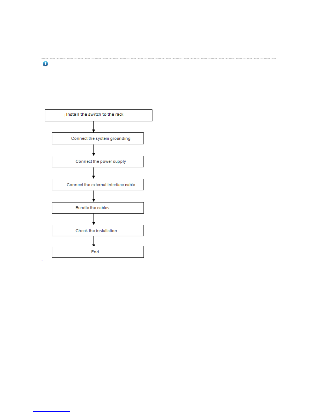
3.1 Installation Procedure
3.2 Confirmations before Installation
Before installation, please confirm the following points:
Whether ventilation requirements are met for the switch
Whether the requirements of temperature and humidity are met for the switch
Whether power cables are already laid out and whether the requirements of electrical current are met
Whether related network adaption lines are already laid out
3.3 Precautions
During installation, note the following points:

Hardware Installation and Reference Guide Product Installation
Connect the power cables of different colors to the corresponding grounding posts.
Ensure that the interface of the power supply cable is well connected to the power interface of the device. The
power cables must be protected using power cable retention clips after they are connected to the device.
Do not place any articles on the switch.
Reserve a spacing of at least 10 cm around the chassis for good ventilation. Do not stack the devices.
The switch should be located at places free from the large power radio launch pad, radar launch pad, and
high-frequency large-current devices. If necessary, electromagnetic shielding should be adopted. For example,
use interface cables to shield cables.
100-meter network cables should be laid inside the equipment room and outdoor cabling of such cables is
prohibited. If outdoor cabling is necessary, take relevant measures for lightning protection.
3.4 Installing the RG-S1800 Series
3.4.1 Mounting the Switch in the Rack
The RG-S1800 series switches are designed with the EIA standard dimensions. RG-S1826 can be installed in 19-inch
rack, while RG-S1808 does not support rack mounting.
Step 1: Take out supplied screws and brackets, and then mount the brackets onto left and right sides of the switch.
Figure 3-2 Attaching the Mounting Brackets to the Switch
Step 2: Place the switch into the rack. Fix the other ends of both brakcets onto the suqre hole strips of the rack by using
screws and cage nuts, as shown in Figure 3-3.
Figure 3-3 Fixing the Brackets to the Rack

Hardware Installation and Reference Guide Product Installation
3.4.2 Mounting the Switch on the Wall
The RG-S1800 series switches can be mounted on a wall (RG-S1808 does not support wall mounting).
Step 1: Take out supplied screws and brackets. And then rotate the brackets by 90° when it is mounted on the wall.
Figure 3-4 Fixing the Switch to the Wall
Step 2: Fix the switch onto the wall by using expansion screws.

Hardware Installation and Reference Guide Product Installation
3.4.3 Mounting the Switch to a Workbench
In some cases, users do not have the 19-inch standard cabinet. The common solution is to place the switch on a clean
workbench. The operation is simple as follows:
Step 1: Attach the four rubber pads to the four corners on the switch bottom.
Figure 3-5 Attaching the Pads to the Switch
2) Step 2: Place the switch on the workbench and ensure good ventilation condition around the switch.
Figure 3-6 Placing the Switch on the Workbench
3.5 Installing the RG-S1800G Series
3.5.1 Mounting the Switch in the Rack
The RG-S1800G series switches are designed with the EIA standard dimensions. The switch can be installed in 19-inch
rack.
Step 1: Take out supplied screws and brackets, and then mount the brackets onto left and right sides of the switch.
Figure 3-7 Attaching the Mounting Brackets to the Switch

Hardware Installation and Reference Guide Product Installation
Step 2: Place the switch into the rack. Fix the other ends of both brakcets onto the suqre hole strips of the rack by using
screws and cage nuts, as shown in Figure 3-8.
Figure 3-8 Fixing the Brackets to the Rack
3.5.2 Mounting the Switch on the Wall
The RG-S1800G series switches can be mounted on a wall.
Step 1: Take out supplied screws and brackets. And then rotate the brackets by 90° when it is mounted on the wall.
Figure 3-9 Fixing the Switch to the Wall

Hardware Installation and Reference Guide Product Installation
Step 2: Fix the switch onto the wall by using expansion screws.
3.5.3 Mounting the Switch to a Workbench
In some cases, users do not have the 19-inch standard cabinet. The common solution is to place the switch on a clean
workbench. The operation is simple as follows:
Step 1: Attach the four rubber pads to the four corners on the switch bottom.
Figure 3-10 Attaching the Pads to the Switch
2) Step 2: Place the switch on the workbench and ensure good ventilation condition around the switch.

Hardware Installation and Reference Guide Product Installation
Figure 3-11 Placing the Switch on the Workbench
3.6 Installing the RG-S1800-P Series
3.6.1 Mounting the Switch to a Workbench
In some cases, users do not have the 19-inch standard cabinet. The common solution is to place the switch on a clean
workbench. The operation is simple as follows:
Step 1: Attach the four rubber pads to the four corners on the switch bottom.
Figure 3-12 Attaching the Pads to the Switch
2) Step 2: Place the switch on the workbench and ensure good ventilation condition around the switch.
Figure 3-13 Placing the Switch on the Workbench

Hardware Installation and Reference Guide Product Installation
3.6.2 Mounting the Switch on the Wall
The RG-S1809-P series switches can be mounted on a wall.
Step1: Drill two holes on the wall. Tap wall anchors into the holes.
Figure 3-14
Step 2: Drive screws into the anchors.
Figure 3-15
Step 3: Mount the switch to wall through the screws.
Figure 3-16

Hardware Installation and Reference Guide Product Installation
Step 4: Complete installation.
Figure 3-17

Hardware Installation and Reference Guide Product Installation
3.7 Installing the RG-S1800G-P Series
3.7.1 Mounting the Switch in the Rack
The RG-S1800G-P series switches are designed with the EIA standard dimensions. RG-S1826G-P can be installed in
19-inch rack.
Step 1: Take out supplied screws and brackets, and then mount the brackets onto left and right sides of the switch.
Figure 3-18 Attaching the Mounting Brackets to the Switch
Step 2: Place the switch into the rack. Fix the other ends of both brakcets onto the suqre hole strips of the rack by using
screws and cage nuts, as shown in Figure 3-19.
Figure 3-19 Fixing the Brackets to the Rack
3.7.2 Mounting the Switch on the Wall
The RG-S1800G-P series switches can be mounted on a wall.
Step 1: Take out supplied screws and brackets. And then rotate the brackets by 90° when it is mounted on the wall.
Figure 3-20 Fixing the Switch to the Wall

Hardware Installation and Reference Guide Product Installation
Step 2: Fix the switch onto the wall by using expansion screws.
3.7.3 Mounting the Switch to a Workbench
In some cases, users do not have the 19-inch standard cabinet. The common solution is to place the switch on a clean
workbench. The operation is simple as follows:
Step 1: Attach the four rubber pads to the four corners on the switch bottom.
Figure 3-21 Attaching the Pads to the Switch
2) Step 2: Place the switch on the workbench and ensure good ventilation condition around the switch.
Figure 3-22 Placing the Switch on the Workbench

Hardware Installation and Reference Guide Product Installation
3.8 Connecting the Power Cord
Make sure the socket is powered off and the switch is properly grounded before the power cord is connected.
Connect the AC power cord
1. Insert the AC power plug into the device.
2. Take out the anti-loose buckle.
3. Install the anti-loose buckle on the rear panel of the device
4. Fasten the anti-loose buckle to the power cord.
5. Connect the other end of the power cord to an external power socket.
6. Power on the device and check whether the status indicator is blinking. Blinking indicates the switch is being
initialized.
Figure 3-23 Connecting the Power Cord
Connect the DC power cord
1. Insert the DC power plug into the device.
2. Connect the other end of the power cord to an external power socket.
3. Power on the device and check whether the status indicator is blinking. Blinking indicates the switch is being
initialized.

Hardware Installation and Reference Guide Product Installation
3.9 Checking after Installation
Before checking the installation, switch off the power supply so as to avoid any personal injury or damage to the
component due to connection errors.
Check that the ground line is connected.
Check that the cables and power input cables are correctly connected.
Check that the 100 meter cables are laid out inside the equipment room. In the case of external cabling, check that
the lightning resistance socket or network interface lightning protector is connected.
Check that sufficient ventilation space is available around the device (over 10 cm).
Hardware Installation and Reference Guide Maintenance and Troubleshooting
4 Maintenance and Troubleshooting
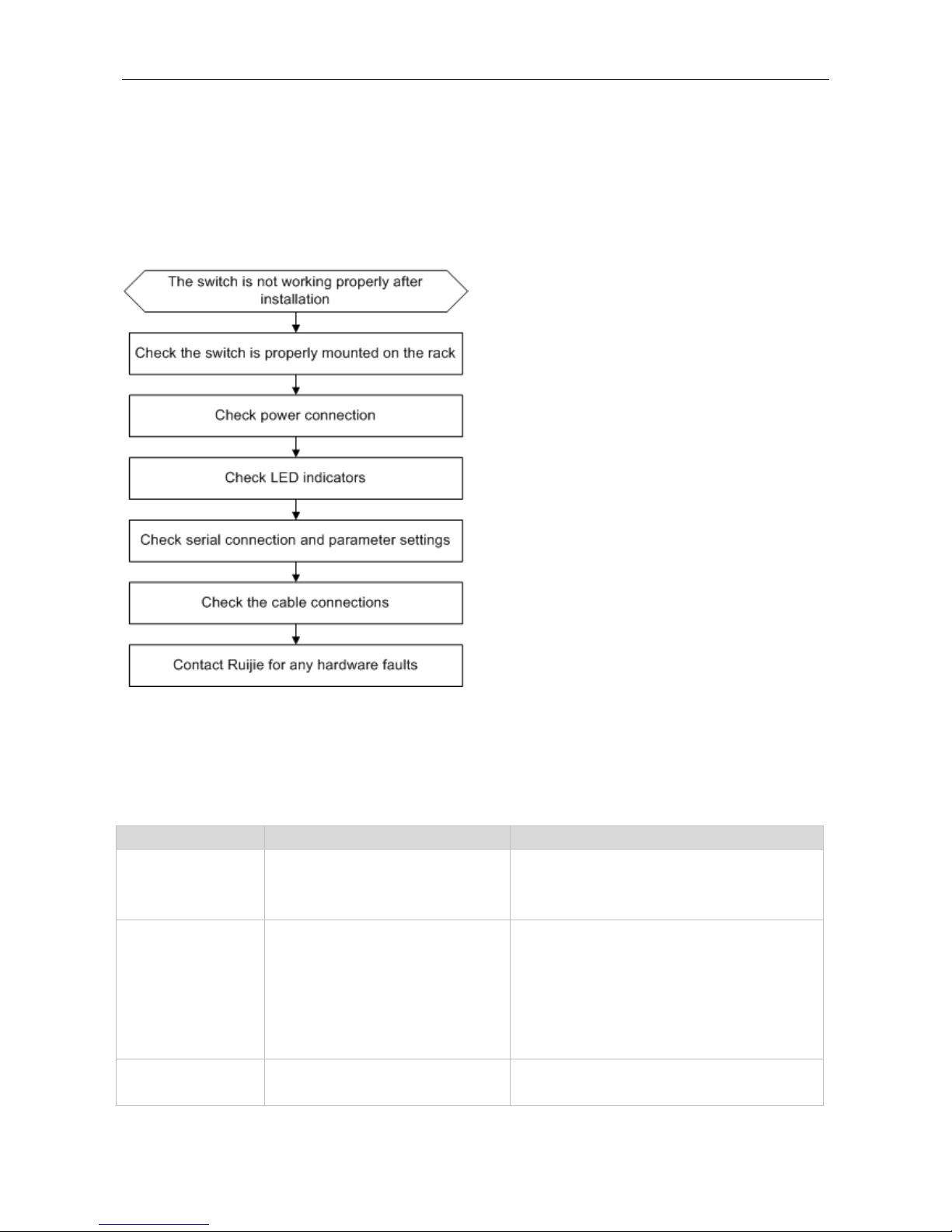
4.1 General Troubleshooting Procedure
4.2 Common Faults
Symptom
Possible Causes
Solution
The PWR indicator is
not on after the switch
is started.
The power supply module does not
supply power.
The power cable is in loose contact.
Check whether the power socket at the equipment
room is normal and whether the power cable of the
switch is in good contact.
The RJ45 port is not in
connectivity or it is
erroneous in
receiving/transmitting
frames.
The connected twisted pair cable is
faulty.
The length of the cable exceeds 100 m.
The port has special configuration that
has no common working mode with the
connected switch.
Replace the twisted pair cable.
Check that the port configuration has the common
working mode with the connected switch.
The fiber port cannot
be connected.
The Rx and Tx ends are connected
reversely.
Switch the Rx and Tx ends of the optical fiber.
Replace the optical module with one of the

Hardware Installation and Reference Guide Maintenance and Troubleshooting
Symptom
Possible Causes
Solution
The interconnected optical module type
does not match.
The fiber type is not correct.
The length of the optical fiber exceeds
that rated of the optical module.
matched type.
Replace the optical fiber with one of the
appropriate type.
Replace the optical fiber with one of the
appropriate length.

Hardware Installation and Reference Guide Appendix A: Connectors and Connection Media
Appendix A: Connectors and Connection Media
1000BASE-T/100BASE-TX/10BASE-T Ports
The 1000BASE-T/100BASE-TX/10BASE-T is a port that supports adaptation of three rates, and automatic MDI/MDIX
Crossover at these three rates.
The 1000BASE-T complies with IEEE 802.3ab, and uses the cable of 100-ohm Category-5 or Supper Category-5 UTP or
STP, which can be up to 100 m.
The 1000BASE-T port uses four pairs of wires for transmission, all of which must be connected. Figure A-1 shows the
connections of the twisted pairs used by the 1000BASE-T port.
Figure A-1 Four Twisted Pairs of the 1000BASE-T
In addition to the above cables, the 100BASE-TX/10BASE-T can also use 100-ohm Category-3, 4, 5 cables for 10 Mbps,
and 100-ohm Category-5 cables for 100 Mbps, both of which can be up to 100 m. Figure A-2 shows the pinouts of the
100BASE-TX/10BASE-T.
Figure A-2 Pinouts of the 100BASE-TX/10BASE-T
Figure A-3 shows the straight-through and crossover cable connections for the 100BASE-TX/10BASE-T.
Figure A-3 Connections of the Twisted Pairs of the 100BASE-TX/10BASE-T

Hardware Installation and Reference Guide Appendix A: Connectors and Connection Media
Optical Fiber Connection
For the optical fiber ports, select single-mode or multiple-mode optical fibers for connection according to the fiber module
connected. The connection schematic diagram is shown in Figure A-4:
Figure A-4 Optical Fiber Connections

Hardware Installation and Reference Guide Appendix B Mini-GBIC Modules
Appendix B Mini-GBIC Modules
We provide appropriate SFP modules (Mini-GBIC) modules according to the types of interfaces of the switch modules.
You can select the module to suit your specific needs. The 100M/1000M SFP module supports the following modules
as well as the 100M/1000M fiber/copper conversion SFP module (Mini-GBIC-GT). The following models and technical
specifications of some 100M/1000M SFP modules are listed for your reference.
Models and Technical Specifications of the Mini-GBIC (SFP) Module
Table B-1 Models and Technical Specifications of the 100M SFP Modules
100M Mini-GBIC
(SFP)
Wavelength
(nm)
Media Type
Core
Size
(μm)
Cabling
Distance
Intensity of
Transmitte
d Light
(dBm)
Intensity of
Received
Light
(dBm)
Suppor
t DDM
(Yes/No)
min
max
min
max
FE-SFP-LX-MM1310
1,310
Multi-mode
fiber
62.5/125
2km
-22
-14
-30
-14
Yes
FE-SFP-LH15-SM1310
1,310
Single-mode
fiber
9/125
15km
-15
-8
-28
-8
Yes
Table B-2 Models and Technical Specifications of the 1000M SFP Modules
1000M Mini-GBIC
(SFP)
Wavelength
(nm)
Media Type
Core
Size
(μm)
Cabling
Distance
Intensity of
Transmitte
d Light
(dBm)
Intensity of
Received
Light
(dBm)
Suppor
t DDM
(Yes/No)
min
max
min
max
MINI-GBIC-SX-MM850
850
Multi-mode
fiber
62.5/125
275m
-9.5
-3
-17 0 No
50/125
550m
MINI-GBIC-LX-SM1310
1,310
Single-mode
fiber
9/125
10km
-9.5
-3
-20
-3
No
GE-eSFP-SX-MM850
850
Multi-mode
fiber
62.5/125
275m
-9.5
-3
-17 0 Yes
50/125
550m
GE-eSFP-LX-SM1310
1,310
Single-mode
fiber
9/125
10km
-9.5
-3
-20
-3
Yes
MINI-GBIC-LH40-SM13
10
1,310
Single-mode
fiber
9/125
40km
-2 3 -22
-3
Yes
MINI-GBIC-ZX50-SM15
50
1,550
Single-mode
fiber
9/125
50km
-5 0 -22
-3
Yes
MINI-GBIC-ZX80-SM15
50
1,550
Single-mode
fiber
9/125
80km
0
4.7
-22
-3
Yes

Hardware Installation and Reference Guide Appendix B Mini-GBIC Modules
MINI-GBIC-ZX100-SM1
550
1,550
Single-mode
fiber
9/125
100km
0 5 -30
-9
Yes
For the optical module with transmission distance exceeding 40 km and more, one on-line optical attenuator
should be added on the link to avoid the overload of the optical receiver when short single-mode optical fibers are
used.
 Loading...