


RG-RSR20-X-28 Series Routers
Hardware Installation and Reference Guide 1.0

Copyright Statement
Ruijie Networks©2018
Ruijie Networks reserves all copyrights of this document. Any reproduction, excerption, backup, modification,
transmission, translation or commercial use of this document or any portion of this document, in any form or by any means,
without the prior written consent of Ruijie Networks is prohibited.
Exemption Statement
This document is provided “as is”. The contents of this document are subject to change without any notice. Please obtain
the latest information through the Ruijie Networks website. Ruijie Networks endeavors to ensure content accuracy and will
not shoulder any responsibility for losses and damages caused due to content omissions, inaccuracies or errors.

Preface
Thank you for using our products. This manual will guide you through the installation of the device.
This manual describes the functional and physical features and provides the device installation steps, hardware
troubleshooting, module technical specifications, and specifications and usage guidelines for cables and connectors.
Audience
It is intended for the users who have some experience in installing and maintaining network hardware. At the same time, it
is assumed that the users are already familiar with the related terms and concepts.
Obtaining Technical Assistance
Ruijie Networks Website: https://www.ruijienetworks.com/
Technical Support Website: https://ruijienetworks.com/support
Case Portal: http://caseportal.ruijienetworks.com
Community: http://community.ruijienetworks.com
Technical Support Email: service_rj@ruijienetworks.com
Skype: service_rj@ruijienetworks.com
Related Documents
Documents
Description
Configuration Guide
Describes network protocols and related mechanisms that supported by the
product, with configuration examples.
Command Reference
Describes the related configuration commands, including command modes,
parameter descriptions, usage guides, and related examples.
Symbol Conventions
Means reader take note. Notes contain helpful suggestions or references.
Means reader be careful. In this situation, you might do something that could result in equipment damage or loss of
data.


1 Product Overview
The RSR20-X-28 series routers are data communication products independently developed by Ruijie Networks Co. Ltd.
by using advanced semiconductor technologies and communication control technologies. Ruijie series routers are
developed in full compliance with international standards, therefore, it is similar to major routers in terms of use and
configuration approach. Network administrators who are familiar with the configuration commands of major routers may
use the routers without receiving training first.
1.1 About the RG-RSR20-X-28
Developed from Ruijie’s RSR (Reliable multi-Services Router), RSR20-X-28, as the next generation access router, is
characterized by its applicability in a variety of access scenarios, such as routing, switching, security, 3G/4G and WiFi.
With improvements in performance, port number, rate and reliability, RSR20-X-28 offers integrated solutions for
enterprise edge networks at minimum costs. The Router provides a consolidated service infrastructure that enables
scalable deployment of new applications to better address the diversified demands for future business development.
RSR20-X-28 is an ideal choice for branch offices of medium and large-sized financial institutions, governments or
enterprises to access multiple services in a cost-efficient way.
Adopting advanced RGOS operation system, RSR20-X-28 supports Ruijie’s patented technologies REF (Ruijie
Express Forwarding), VCPU (virtual CPU) and X-Flow. All these leading technologies guarantee stable forwarding
even when multiple services are enabled on the Router. Because of Stateful Firewall, RSR20-X-28 is good at resisting
flow attacks. The Router delivers plentiful backup solutions, QoS/HQoS characteristics, service-rich features, including
MPLS, VPN, multicast, IPv6, VoIP, NAT and MVRF. In this manner, users do not need to purchase additional software
Licenses or service modules.
Supporting HSIC service modules, RSR20-X-28 totally delivers up to 10Gbps bandwidth. The Router also supports
expansion of 10G Ethernet interface modules and other WAN and LAN modules of diverse types, multiple functions
and high intensity. Such expandability serves as a foundation for more combination possibilities. Plugging and
unplugging of hot-swappable HSIC service modules have no influence on forwarding services of other operating
modules. Plus, RSR20-X-28 supports alternating/direct current power supply redundancy, which helps enhance
reliability.
Aimed at offering users simplistic and efficient network, RSR20-X-28 supports simplistic network solutions, including
device virtualization, WAN port aggregation, IDA and ITO.
Different SIC slots support different extension service modules to flexibly meet users’ requirements.
Table 1-1 Extension Service Modules Supported by the RSR20-X-28 Router
Slot
Supported Service Modules
Slot 2
HSIC-2E1/CE1, HSIC-2HS, HSIC-4G-LTE
Slot 3
HSIC-2E1/CE1, HSIC-2HS, HSIC-4G-LTE
Slot 4
RG-PA60, HSIC-2E1/CE1, HSIC-2HS, HSIC-4G-LTE

Slot 5
RG-PA60, HSIC-2E1/CE1, HSIC-2HS, HSIC-4G-LTE
Up to four HSIC modules are supported per router. Modules with OFL buttons are hot-swappable, while modules
without OFL buttons are not hot-swappable. HSIC-2E1/CE1 and HSIC-2HS support hot swapping. HSIC-4G-LTE
does not support hot swapping.
Up to two power supply modules are supported. Slot 4 and Slot 5 support power supply modules. Hot swapping is
supported.
Up to two DHSIC modules are supported. Modules with OFL buttons are hot-swappable, while modules without
OFL buttons are not hot-swappable.
Slot 4 and Slot 5 support DHSIC modules. Hot swapping is supported.
Technical Specifications
Table 1-2 Technical Specifications of the RSR20-X-28 Series Router
Model
RSR20-X-28
Interfaces
One Console/AUX combo port
One USB port
One SD card slot
One FUNC button
24 10/100/1000Mbps Ethernet ports
Four GE copper ports (including two GE combo ports)
HSIC Slots
4 (Two slots only support HSIC modules; another two slots support HSIC modules,
DHSIC modules and power supply modules. )
Processor
64-bit multinuclear processor
BOOT ROM
8MB
NAND FLASH
256MB
DDR III
1GB
Dimensions
(W x H x D)
440mm x 44mm x 340mm
Input Voltage
100VAC to 240VAC, 50 Hz to 60 Hz
Power Consumption
< 48W
Operating Temperature
0°C to 45°C (32°F to 113°F)

Storage Temperature
-40°C to 70°C (-40°F to 158°F)
Operating Humidity
5% to 95% RH (non-condensing)
Storage Humidity
5% to 95% RH (non-condensing)
1.1.1 Product Features
Access density and processing capability
The RSR20-X-28 supports four HSIC slots, 24 GE Ethernet ports, and four GE copper ports (including two GE combo
ports). The Router provides one FUNC multi-functional button to upgrade the RGOS operating system as well as one
SD card slot and one USB port to save configuration to storage devices. These make the router an ideal choice for
large/medium-sized branches.
Reliability
The router adopts backup center technologies, which greatly improves network reliability. Various backup modes are
available for high reliability requirements.
Compatibility
The router is fully compatible with devices from other vendors.
Power supply
By using high-quality standard power supplies, the router provides protection against surge, overvoltage, undervoltage,
overcurrent to deliver stable and reliable output. In addition, it supports transient power interruption protection and
power redundancy.
Construction
With the rack mount 1U chassis with EMI shielding, the router can be installed in a bracket or a workbench.
RSR20-X-28 is highly resistant to shock, high/low temperature, and electromagnetic radiation, and works stably.
Certificate
The router has passed the network access license (NAL) testing by the Ministry of Information Industry (MII), P.R.
China.
1.1.2 Product Image and LED Indicators
Front Panel
Figure 1-1 Front panel of RSR20-X-28 Router

2
3
4
6
8 10
11
121314
9
5
7
1
Note:
1: Mounting hole for the power cord buckle
2: Power port
3: Power switch
4: 24 10/100/1000M Ethernet ports
(GE1/0~GE1/23)
5: 24 LEDs for Ethernet ports
6: Four GE copper ports (GE0/0~GE0/3)
7: Four LEDs for GE copper ports
8: Two SFP fiber/copper combo ports
9: Two LEDs for SFP fiber/copper combo ports
10: USB slot
11: Console/AUX combo port
12: SD card slot
13: FUNC button
14: (From left to right) SD LED, USB LED, PWR_BAK
LED, PWR LED, SYS LED
LED Indicators
Table 1-3 LED Indicators on the RSR20-X-28 Router
LED
Panel Identification
State
Meaning
System status LED
SYS
Off
The router is not receiving power, or the router is
reeving power but the system fails.
Solid green
The system is operational.
Blinking green
The system starts up.
Solid red
The system is faulty.
Active power status
LED
PWR
Solid green
Power supply is operational.
Solid yellow
No power supply is available.
Backup power status
LED
PWR_BAK
Solid green
Two or more than two backup power are
receiving power.
Off
One or none backup power is receiving power.
USB device status
USB
Off
No USB device is inserted.
Solid green
The USB device is initialized and is not
exchanging data.
Blinking green
The USB device is exchanging data.
Solid red
The USB device is faulty.
SD card status
SD
Off
No SD card is inserted.
Solid green
The SD card is initialized and is not exchanging
data.
Blinking green
The SD card is exchanging data.
Solid red
The SD card is faulty.
SFP port status
SFP
Off
The port is NOT connected.
Solid yellow
The port is connected at 100Mbps.
Blinking yellow
The port is connected at 100Mbps and is
exchanging data.
Solid green
The port is connected at 1,000Mbps.
Blinking green
The port is connected at 1,000Mbps and is
exchanging data.
GE copper port status
1-24
Off
The port is NOT connected.
Solid yellow
The port is connected at 10/100Mbps.
Blinking yellow
The port is connected at 10/100Mbps and is
exchanging data.
Solid green
The port is connected at 1,000Mbps.
Blinking green
The port is connected at 1,000Mbps and is
exchanging data.
Back Panel
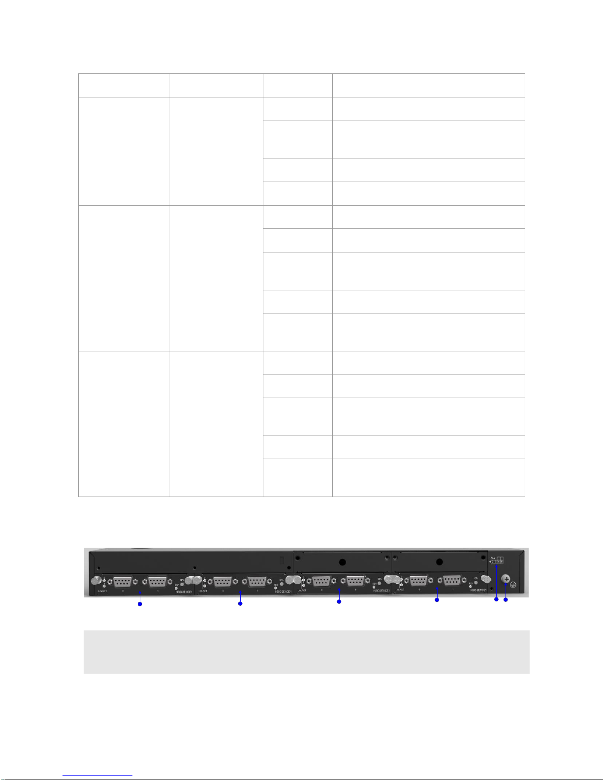
Figure 1-2 Back Panel of RSR20-X-28 Router
15 16
17
18 19
20
Note:
15: SLOT 2
16: SLOT 3
17: SLOT 4
18: SLOT 5
19: Grounding point
20: Slot identifier

If you cannot determine the number of the slot where the current module resides, you can run the show slots
command in privileged EXE mode. The router version information includes the slot number of each module.
SLOT 4 and SLOT 5 support DHSIC/power modules.
1.2 About Fixed Ports
This section describes fixed ports on the RSR20-X-28 series router.
1.2.1 Console/Auxiliary Combo Port
Features
The RSR20-X-28 series router provides one Console/AUX combo port.
Table 1-4 Specifications of the Console/AUX Combo Port
Index
Parameter
Interface Standard
EIA/TIA-RS232
Connector
RJ-45
Rate
Supports 9,600bps, 57,600bps and 115,200bps baud rates. The default is 9,600bps.
Cables
Use DB9F-to-RJ45
cables.
1.2.2 GE Ports
Port Image and LED Indicators
Figure 1-3 Appearance of the 24 GE ports
For descriptions of GE port Link/ACT LED indicators, see the “LED Indicators” section in Chapter 1.
Features
An RSR20-X-28 series router provides 24 fixed 10/100/1000Mbps copper ports. And RJ45 connectors are used for
connection.

The following table describes the basic features of the copper ports.
Table 1-5 Specifications of GE ports
Protocol
IEEE Std 802.3-2012
Quantity
24
Interface Type
10Base-T/100Base-TX/1000Base-T interfaces
Cables
1000BASE-T interfaces: 100-ohm Category 5e UTP/STP cables, maximum cabling distance 100m
100BASE-TX interfaces: 100-ohm Category 5/5e UTP/STP cables, maximum cabling distance 100m
10BASE-T interfaces: 100-ohm Category 3/4/5/5e UTP/STP cables, maximum cabling distance 100m
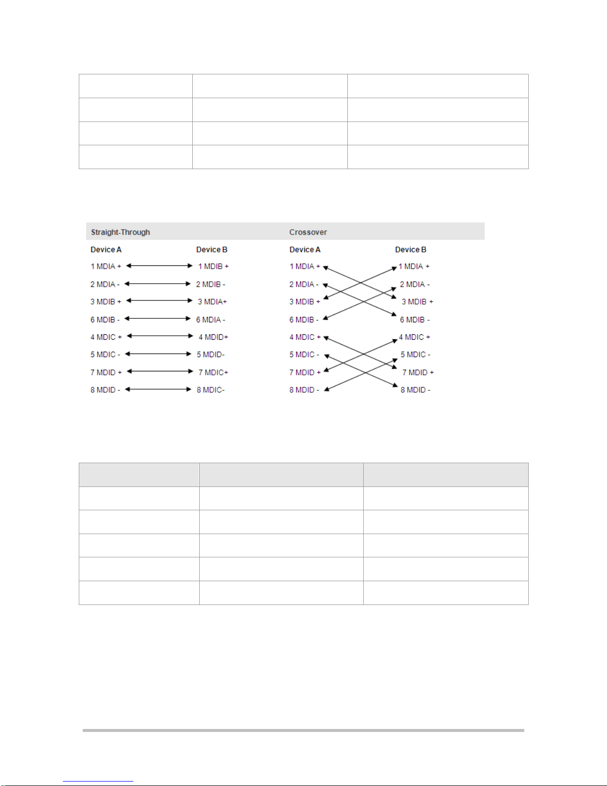
If the port supports Auto-MDI/MDI-X, both straight-through and crossover cables can be used. RSR20-X-28 supports
MDI/MDI-X.
Considering that you may customize cables, the following section describes how to wire straight-through and crossover
cables.
As shown in the following figure, the pins of the RJ-45 connector are numbered 1 to 8, counting from left to right when
the connector is viewed from the side without the latching tab.
Figure 1-4 RJ-45 Connector Pin Number
Table 1-6 1000BASE-T Pin Assignments
Pin
MDI Mode
MDI-X Mode
1
Media Dependent Interface A+
Media Dependent Interface B+
2
Media Dependent Interface A-
Media Dependent Interface B-
3
Media Dependent Interface B+
Media Dependent Interface A+
4
Media Dependent Interface C+
Media Dependent Interface D+
5
Media Dependent Interface C-
Media Dependent Interface D-
6
Media Dependent Interface B-
Media Dependent Interface A-
7
Media Dependent Interface D+
Media Dependent Interface C+
8
Media Dependent Interface D-
Media Dependent Interface C-
When 1000BASE-T interfaces are in use, connect all four pairs of pins. The pin connection rule is shown in Table 1-7.
Table 1-7 1000BASE-T Connection
Table 1-8 100BASE-TX/10BASE-T Pin Assignments
Pin
MDI Mode
MDI-X Mode
1
Output Transmit Data+
Input Receive Data+
2
Output Transmit Data-
Input Receive Data-
3
Input Receive Data+
Output Transmit Data+
6
Input Receive Data-
Output Transmit Data-
4, 5, 7, 8
Not Used
Not Used

Table 1-9 100BASE-TX/10BASE-T Connection
1.2.3 GE and SFP Ports
Two among the four GE ports are combo ports. SFP ports support 100/1000M optical modules.
Port Image and LED Indicators
The following figure shows the fixed GE and SFP ports.
Figure 1-5 GE and SFP Ports
For descriptions of GE and SFP port Link/ACT LED indicators, see the “LED Indicators” section.
Features
The fiber port uses a Small Form-Factor Pluggable (SFP) module.
SFP ports:
The SFP ports support the following SFP modules, you can select according to your needs:
Table 1-10 Available 1,000M SFP Module Specifications
SFP Module
Module Type
Connector
Type
Transmission Distance
Mini-GBIC-SX
1-port 1000BASE-SX mini GBIC transceiver
LC
-
Mini-GBIC-LX
1-port 1000BASE-LX mini GBIC transceiver
LC
-
Mini-GBIC-LH40
1-port 1000BASE-LH mini GBIC transceiver
LC
40km

Mini-GBIC-ZX50
1-port 1000BASE-ZX mini GBIC transceiver
LC
50km
Mini-GBIC-ZX80
1-port 1000BASE-ZX mini GBIC transceiver
LC
80km
Table 1-11 Available 100M SFP Module Specifications
SFP Module
Module Type
Fiber
FE-SFP-LX-MM1310
155M multi-mode FE-SFP-LX-MM1310
62.5/125um multimode optical fiber
FE-SFP-LH15-SM1310
155M single-mode FE-SFP-LH15-SM1310
9/125um single-mode optical fiber
The optional transmission media are as followings:
Table 1-12 Optional Transmission Media and Transmission Distances
Media
Wavelength
Fiber
Maximum Transmission Distance
100BASE-FX
1,310nm
9/125um single-mode optical fiber
2 km, 15 km
1000BASE-SX
850nm
62.5/125um multimode optical fiber
220m
50/125um multimode optical fiber
500m
1000BASE-LX
1,310nm
62.5/125um multimode optical fiber
550m
50/125um multimode optical fiber
550m
9/125um single-mode optical fiber
10km
1000BASE-LH
1,310nm
9/125um single-mode optical fiber
40km
1000BASE-ZX
1,550nm
9/125um single-mode optical fiber
50km, 80km
1.2.4 USB Port
Port Image and LED Indicators
The following figure shows the fixed USB ports.
Figure 1-6 USB Port

For descriptions of USB port indicator, see the “LED Indicators” section.
Features
The RSR20-X-28 series router provides one fixed USB port, through which the user can read configurations from the
USB device, or save configurations to the USB device.
Table 1-13 Specifications of the USB Port
Index
Parameters
Interface Standard
USB 2.0
Connector
USB Host
Rate
1.5Mbps, 12Mbps, 480Mbps
Interface Type
Host
Hot Swapping
Supported
The hot swapping for the USB device must strictly follow the “Configuring Reliability” chapter in the related
software configuration guide. For the avoidance of system abnormality, hot swapping is not allowed unless the
command for unplugging the USB is entered.
The USB device here refers to USB flash disks. Products by mainstream manufacturers are recommended, such
as Kingston and Sandisk.
USB devices only support
.FAT32
files. Non-.
FAT32
files should be converted to the
.FAT32
format before being
recognized.
Cables
If you connect a USB device with a USB extension cable, the cable must be less than 5 meters.
1.2.5 SD Card Slot
Port Image and LED Indicator
Figure 1-7 SD Card Slot
For descriptions of SD card indicator, see the “LED Indicators” section.

Features
The RSR20-X-28 series router provides one fixed SD card slot, through which the user can read configurations from an
SD card, or save configurations to the SD card. You can save the RGOS operating system to the SD card, and upgrade
the operating system by pressing FUNC button on the panel.
Table 1-14 Specifications of the SD Card Slot
Index
Parameters
Interface Standard
SD/SDHC
Connector
SD connector
Rate
5Mbps/sec max
Interface Type
Device
SD Card
Ruijie Networks SDHC card/ Kingston/ 4GB/ class_4
Hot Swapping
Supported
The hot swapping for the SD device must strictly follow the “Configuring Reliability” chapter in the related software
configuration guide. For the avoidance of system abnormality, hot swapping is not allowed unless the command
for unplugging the SD card is entered.
SD cards only support
.FAT32
files. Non-.
FAT32
files should be converted to the
.FAT32
format before being
recognized.
Cables
N/A
1.2.6 FUNC Button
FUNC Button Image
Figure 1-8 FUNC Button
The FUNC button is close to the SD card slot on the front panel. It is used for one-click upgrade. To avoid careless
touching, the button is designed to be pressed using a tiny needle.

Features
When an SD card or a USB flash disk is inserted into the device, press the FUNC button. Then, the system searches
for the installation packages and configuration files that are applicable to the current device in the root directories of the
SD card and USB flash disk in sequence. After successfully finding the corresponding installation packages and
configuration files, the system checks the validity of the files and then upgrades the device by using the installation
packages and configuration files. After the upgrade, the system resets and restarts based on the new software versions
and configuration files.
When NO SD card or a USB flash disk is inserted into the device, press the FUNC button to reset the system.
When a storage medium is inserted, the system scans for an SD card first. If no SD card is inserted or the inserted
SD card does not contain applicable installation packages or configuration files, the system scans for a USB flash
drive. If neither the inserted SD card nor the USB flash drive contains applicable installation packages or
configuration files, the software versions and configuration files are not upgraded. Only the system resets, and
restarts based on the original software versions and configuration files.
One-click upgrade of the software version must strictly follow the “Configuring Reliability” chapter in the related
software configuration guide. After the system has scanned an SD card or USB flash drive, press the FUNC
button shortly.
1.3 About Service Modules
This section describes the features of service modules supported by the RSR20-X-28 series router.
1.3.1 HSIC-2HS Synchronous Interface Module
Product model:
HSIC-2HS
Image and Indicators
Figure 1-9 HSIC-2HS High-Speed Synchronous Serial Interface Module
Each module has an interface status indicator (Link/ACT indicator) and the module RDY indicator. And an OFL hot
swapping button is provided.
The following table describes LED indicators.
Table 1-15 LED Indicators on the HSIC-2HS Module
LED
Panel Identification
State
Meaning

Module status LED
RDY
Off
The module is not receiving power; the module is
not properly inserted; or the module is removable.
Blinking green
Initialization is in progress
Solid green
Initialization is complete and the module is
operational.
Port 0-1 status LED
Link/ACT
Off
The port is not connected.
Blinking green
The port is connected properly and is transceiving
data.
Solid green
The port is properly connected.
Hot Swapping Button
OFL
-
Press the button for more than 3s. When the RDY
indicator starts to blink, release the button, and
the automatic unmounting of the module is
complete. After the RDY indicator turns off,
remove the module.
Features
The following table describes basic features of high-speed synchronous serial interface (HS):
Table 1-16 Specifications of the SIC-1HS Module
Protocol
V.24 and V.35 are supported with cable automatic identification.
Rate
The synchronous port of a single-synchronous module supports from 9,600bps to
8,192,000bps.
Indicator
There are three LED indicators.
Two LEDs indicating the Link/ACT status of one port, which turn solid green when the
physical link is set up and the upper layer protocol is up and turns blinking green when
the port is exchanging data.
One LED indicating the RDY status of one service module, which turns on when the
supervisor module identifies the service module.
Interface
DB26
Environmental
Operating temperature: 0°C to 45°C (32°F to 113°F)
Operating humidity: 5% to 95% RH;
Storage temperature: –40°C to 70°C (-40°F to 158°F)
EMC
EMI: GB 9254-2008 Class A
EMS: GB/T 17618-1998

Cables
The following cables can
be used:
V.24 DTE
V.24 DCE
V.35 DTE
V.35 DCE
V.35 DTE-V.35 DCE
The figures of these cables are as below.
V.24 DTE
One end of this cable is the DB25 male connector, and the other end is the DB26 male connector.
Figure 1-10 V.24 DTE Cable
V.24 DCE
One end of this cable is the DB25 female connector, and the other end is the DB26 male connector.
Figure 1-11 V.24 DCE Cable
V.35 DTE
One end of this cable is the DB34 male connector, and the other end is the DB26 male connector.

Figure 1-12 V.35 DTE Cable
V.35 DCE
One end of this cable is the DB34 female connector, and the other end is the DB26 male connector.
Figure 1-13 V.35 DCE cable
V.35 DTE-V.35 DCE
Both ends of this cable are DB26 male connectors.
Figure 1-14 V.35 DTE-V.35 DCE Cable
The cables are customer supplied. All types of HSIC-2HS cables connect to the router through the DB26 interface.
Choose connectors of the right type when purchasing cables. For the use of the cables, see Chapter 6.
1.3.2 HSIC-2E1/CE1 Interface Module
HSIC module model: HSIC-2E1/CE1
Image and Indicators
The following figure shows the image of a 2-port E1/CE1 interface module.

Figure 1-15 HSIC-2E1-CE1
Each module has an interface status indicator (Link/ACT indicator) and the module RDY indicator. And an OFL hot
swapping button is provided.
The following table describes LED indicators.
Table 1-17 LED Indicators on the SIC-1E1-F Module
LED
Panel Identification
State
Meaning
Module status LED
RDY
Off
The module is not receiving power; the module is
not properly inserted; or the module is removable.
Blinking green
Initialization in progress
Solid green
Initialization is complete and the module is
operational.
Port 0-1 status LED
Link/ACT
Off
The port is not connected.
Blinking green
The port is connected properly and is
transceiving data.
Solid green
The port is properly connected.
Hot Swapping Button
OFL
-
Press the button for more than 3s. When the RDY
indicator starts to blink, release the button, and
the automatic unmounting of the module is
complete. After the RDY indicator turns off,
remove the module.
Features
The following table describes the basic features.
Table 1-18 Specifications of the HSIC-2E1/CE1 Module
Number of Ports
Two
Interface Type
DB9 female connector
Cables
Balanced cables or non-balanced cables
Standard Compliance
ITU-T G.703

Operating Temperature
Operating temperature: 0°C to 45°C (32°F to 113°F)
Storage temperature: -40°C to 70°C (-40°F to 158°F)
Humidity
Operating humidity: 5% to 95% RH
EMC
EMI: GB 9254-2008 Class A
EMS: GB/T 17618-1998
Cables
The following cables are provided:
Balanced cable with the crystal connector
Balanced cable with the crystal jack
Non-balanced cable
Balanced cable with the RJ-45 Plug
One end is the DB9 male connector, and the other end is the RJ-45 plug. The characteristic impedance of the cable is
120Ω.
Figure 1-16 Balanced Cable with the RJ-45 Plug
Considering that you may customize cables, the following section describes connection modes and the signal.
Table 1-19 Signals of the DB9 Male to RJ-45 Plug Cable
DB9M
RJ-45 Plug
Signal
1 5 RX Ring
2 4 RX Tip
4 1 TX Tip
5 2 TX Ring
Balanced cable with the RJ-45 jack
One end is the DB9 male connector, and the other end is the RJ-45 jack. The characteristic impedance of the cable is
120Ω.

Figure 1-17 Balanced Cable with the RJ-45 jack
Considering that you may customize cables, the following section describes connection modes and the signal.
Table 1-20 Signals of the DB9 Male to RJ-45 Jack Cable
DB9M
RJ-45 Jack
Signal
1 2 RX Ring
2 1 RX Tip
4 4 TX Tip
5 5 TX Ring
Non-balanced cable
One end is the DB9 male connector, and the other end is attached with two male BNC connectors. The characteristic
impedance of the cable is 75Ω
Figure 1-18 Non-Balanced Cable
The cables are customer supplied. For the use of cables, see Chapter 6.
1.3.3 HSIC-4G-LTE Interface Module
SIC module model: HSIC-4G-LTE
Image and Indicators

Figure 1-19 HSIC-4G-LTE Module
Table 1-21 LED Indicators on the HSIC-4G-LTE Module
LED
Panel Identification
State
Meaning
Module status LED
RDY
Off
The module is not receiving power.
Solid green
Initialization is complete.
Network status LED
WWAN
Off
Indicates failed dialing.
Blinking green
The module is transceiving data.
Solid green
Indicates successful dialing.
4G service LED
4G
Off
Indicates NO 4G service.
Solid green
Indicates effective 4G service.
3G service LED
3G
Off
Indicates NO 3G service.
Solid
Indicates effective 3G service.
Received signal
strength indication
LED
RSSI
Off
Indicates NO or weak signal.
Blinking green
Indicates moderate signal.
Solid green
Indicates strong signal.
HSIC-4G-LTE does not support hot swapping. If you need to remove the module, power off the device to avoid
damages to the module or the device.
Features
The following table describes the basic features:
Table 1-22 Specifications of the HSIC-4G-LTE Module
Number of Ports
One 4G port

Interface Type
Two SMA-J connectors for antenna connection
Cables
4G antenna
Rate
Mode
Maximum rate for downlink
Maximum rate for uplink
LTE-FDD
100Mbps
50Mbps
LTE-TDD
61Mbps
18Mbps
UMTS HSPA+
42Mbps
5.76Mbps
CDMA2000 1xEV-DO
14.7Mbps
5.4Mbps
TD-SCDMA
4.2Mbps
2.2Mbps
EGDE
236.8Kbps
118Kbps
GPRS
85.6Kbps
85.6Kbps
Operating
Temperature:
Operating temperature: 0°C to 45°C (32°F to 113°F)
Storage temperature: -40°C to 70°C (-40°F to 158°F)
Humidity
Operating humidity: 5% to 95% RH
EMC
EMI: GB 9254-2008Class A
EMS: GB/T 17618-1998
Antenna and Installation
One HSIC-4G-LTE module requires 2 antennas. Antennas are purchased separately. Antenna models are listed in
“Ordering Information” section.
Insert the two external antennas into ANT0 and ANT1 ports on the module respectively, and then rotate the antennas
to tighten the connection.
External antennas are not hot-pluggable. Therefore, installing or removing external antennas require power off of
the router.
1.4 Power Supply Module
1.4.1 RG-PA60 Power Supply Module
Image

Figure 1-20 RG-PA60
Indicator
Table 1-23 LED Indicators on the RG-PA60 Module
LED
Panel Identification
State
Meaning
Module status LED
RDY
Off
The module is faulty.
Solid green
The module is operational.
Features
Table 1-24 Specifications of the RG-PA60 Module
Model
RG-PA60
Rated AC Voltage Range
100VAC to 240VAC, 50-60Hz
Max AC Voltage Range
90VAC to 264VAC, 50-60Hz
Max Output Power
60W
Hot Swapping
Supported
Redundancy
Support Active-Backup power redundancy
Over-Voltage Protection
Supported
Over-Current Protection
Supported
Power Cord
10A power cord
Dimensions
(W x D x H)
98.2mm x 41mm x 176mm (connector excluded)
Operating Temperature
0°C to 45°C (32°F to 113°F)
Storage Temperature
-40°C to 70°C (-40°F to 158°F)
Operating Humidity
5% to 95% RH (non-condensing)

Storage Humidity
5% to 95% RH (non-condensing)
1.5 Features of RSR20-X-28 Series Routers
For software functions, see the supporting software description.
1.5.1 Supporting Multiple Protocols
Applicable to various network environments.
Providing RJ-45 interfaces for twisted pairs and SFP ports, supporting Ethernet, ARP, and 802.1Q protocols.
Supporting various WAN protocols, including X.25, frame relay, HDLC, PPP, and SLIP.
Supporting the TCP/IP protocol stack and the protocols such as IP, Internet Control Message Protocol (ICMP),
Internet Group Management Protocol (IGMP), TCP and UDP on the network layer.
Supporting multiple dynamic routing protocols over IP, including RIP (V1/V2), RIPng, Open Shortest Path First
(OSPF) (V1/V2/V3), and policy-based routing.
Supporting the Simple Network Management Protocol (SNMP).
Supporting Telnet and reverse Telnet.
Supporting Dynamic Host Configuration Protocol (DHCP) Server, DHCP Client, DHCP Relay, and Trivial File
Transfer Protocol (TFTP).
Supporting backup, Virtual Router Redundancy Protocol (VRPP) with high reliability.
Supporting Point-to-Point Protocol over Ethernet (PPPOE).
Supporting DNS static domain name resolution and Dynamic Domain Name Server (DDNS). DNS indicates
Domain Name System.
Supporting upgrade over the asynchronous file transfer protocols of X-MODEM.
Supporting NAT/NAT-PT, ACL and AAA.
Supporting Internet Protocol Security (IPSEC), Layer 2 Tunneling Protocol (L2TP), and Point to Point Tunneling
Protocol (PPTP).
Supporting complete MPLS VPN.
1.5.2 User-Friendly Interfaces
Providing standard operating interfaces and intuitive configuration procedures with each command described in
details in on-line help.
Providing descriptions and examples of each command as well as comprehensive fault analysis.
1.5.3 Powerful Backup Function
Supporting route backup through routing protocols.
Supporting the interface backup function

1.5.4 Multiple Diagnosis and Management Tools
Providing complete debugging and tracing tools as well as complete DEBUG commands for easier accurate
location of various network faults.
Providing rich statistics and information display functions to allow the users to easily know the network
performance and running status.
Supporting SNMP for monitoring and controlling the router by using common network management software.
Supporting login through terminals.
1. Supporting configuration over the Console port
2. Supporting login and configuration over Telnet.
3. Supporting login and configuration over the serial port.
4. Supporting login and configuration over remote dial-up.
1.5.5 Superior Security
Using perfect firewall and IP packet filtering technology to enforce strict check on network addresses, port
numbers, or protocol types.
Supporting AAA and RADIUS.
Realizing Password Authentication Protocol (PAP) and Challenge Handshake Authentication Protocol (CHAP) on
Point-to-Point Protocol (PPP), supporting callback, and enhancing security.
Providing level-based password check and security logs.
Implementing dynamic routing-protocol password/key authentication in OSPF and RIP V2.
Supporting NAT.
Providing IPSEC/IKE data encryption
Supporting GRE tunnel encapsulation
Providing VLAN technology
1.5.6 Multiple Terminal Functions
Enabling both the synchronous and asynchronous ports to connect the terminals.
Supporting the auto command function (automatically run commands) and the user-based auto command
function (allow different users to run different commands) on terminal ports.
Supporting the command alias and telnet script, which can be used together with the auto command function to
directly log in to the server after pressing Enter on the terminal.
Supporting the fixed terminal dial-up function based on different operating systems, where a terminal uses the
same terminal number for multiple times of login.
Supporting the real terminal. The terminal logs in to the server over the router and act as a real terminal (tty) for
the server, not needing the modification of the old programs, thereby protecting the existing investment.

Implementing the router-based multi-screen terminal function, which allows the terminal to easily switch over
between different servers or different screens of one server.
Supporting the reverse Telnet function, which enables easy management of various serial port devices over a
router.
1.5.7 Easy Upgrade
Supporting the asynchronous file transfer X-MODEM protocol, which allows the download of new versions over
the Console port or synchronous port in various operation environments (Windows XP, Windows NT, UNIX, and
DOS).
Supporting the download of the new software versions over TFTP.
Supporting BOOTROM online upgrade.
Supporting the USB device and SD card for one-click upgrade.
Supporting dual BOOTROM.
2 Preparing for Installation
2.1 Precautions
Routers are critical repeaters in network connection, and affect the operation of the whole network.
The following are recommended during the installation and use of a router:
Keep the router dry.
Place the router away from heating sources.
Ensure the normal grounding.
Wear electrostatic discharge (ESD) straps during installation and maintenance.
Do not wear any loose clothes that may hook the components. Therefore, fasten your belts, scarves, and tuck the
sleeves.
Keep the tools and components away from walking areas.
Use Uninterruptible Power Supply (UPS) to avoid power failure as well as power interference.
Replace the battery with an equal one made by the same factory.
Risk of Explosion if battery is replaced by an incorrect type.
Dispose or used batteries according to the instructions.
2.2 Installation Environment Requirements
Ruijie routers are intended for indoor use. For their normal operation and maximum service life, they must be
installed at locations that meet the following requirements:
Temperature and humidity requirements
Cleanness requirements
Anti-static requirements
Anti-interference requirements
Anti-lightning requirements
Installation platform check
2.2.1 Temperature and Humidity Requirements
To ensure the normal operation and maximize the service life of a router, you should keep proper temperature and
humidity in the equipment room. If the relative humidity is high for a long time, the insulating materials may have
poor insulation, electric leakage or other mechanical performance degrade may occur. And if the relative humidity is
too low, the insulating washers may become dry and shrink, which may cause loosened screws. In addition, static
electricity may easily occur in dry weathers, harming the internal circuitry of the router. High temperature will speed
the aging of insulation materials, lowering the router's reliability and shorten its service life.
The following are Ruijie RSR20-X-28 series routers' Requirements for the temperate and humidity requirements:
Temperature: 0ºC to 45ºC (32ºF to 113 ºF)
Relative humidity: 5%–95% RH
The ambient temperature and humidity refer to the values measured at the place 1.5m above the floor and 0.4m
in the front of the router rack without protective boards.
The temperature and humidity requirements may be different for different products. For details, see descriptions
about the characteristic parameters for each product.
2.2.2 Cleanness Requirements
Dust poses a serious threat to device operation. Dust that falls onto the surface of the device can be absorbed onto
metal contact points by static electricity, resulting in poor contact. Electrostatic absorption of dust occurs more easily
when the relative humidity is low, which may shorten the useful life of the device and cause communication failures.
The following table describes Ruijie routers' requirements for the dust content and granularity in the equipment
room:
Maximum
diameter (μm)
0.5
1
3
5
Maximum
concentration
(Particles/m3)
1.4 ×
107
7 × 10⁵
2.4 × 10⁵
1.3 × 10⁵
Besides, the content of salts, acids and sulfides in the air are also strictly limited for the equipment room. These
substances can accelerate metal corrosion and aging of some parts. The following table describes the limit of some
hazardous gases such as SO2, H2S, NO2 and Cl2 in the equipment room.
Gas
Average (mg/m3)
Maximum (mg/m3)

SO2
0.2
1.5
H2S 0 0.03
NO2
0.04
0.15
NH3
0.05
0.15
Cl2
0.01
0.3
2.2.3 Anti-static Requirements
The router circuitry is designed with anti-static protection, but excessive static electricity may still damage router
circuit boards. The static electricity of the network connected with the routers comes largely from the following
sources:
Outdoor electric field produced by the high-voltage supply cable and lightning.
Indoor systems such as the indoor floor and the entire structure.
Therefore, the following requirements must be met:
Ensure proper grounding of the device and floor.
Prevent indoor dust.
Maintain proper temperature and humidity.
Wear ESD wrist straps and ESD lab coats when touching a circuit board.
Put the removed circuit board face up on an anti-static workbench or in an electromagnetic shielding bag.
Touch the external edge of the board and avoid touching the parts on the board directly with hands when
observing or carrying the detached circuit board.
2.2.4 System Grounding Requirements
A good grounding system is the basis for the stable and reliable operation of the RSR20-X-28 and the key to prevent
lightning stroke and resist interference. Please carefully check the grounding conditions on the installation site
according to the grounding requirements, and perform grounding properly as needed.
2.2.5 Safety Grounding
The equipment using AC power supply must be grounded by using the yellow/green safety grounding cable.
Otherwise, when the insulating resistance decreases the power supply and the enclosure in the equipment, electric
shock may occur.
The building installation shall provide a means for connection to protective earth, and the equipment is to be
connected to that means.
2.2.6 EMC Grounding
The ground required for EMC design includes shielding ground, filter ground, noise and interference suppression,
and level reference. All the above constitute the comprehensive grounding requirements. The grounding resistance
should be less than 1Ω.

2.2.7 Anti-interference Requirements
Anti-interference indicates the electromagnetic and current interference. The following are the anti-interference
requirements:
Take effective measures for the power system to prevent the interference from the electric grid.
Separate the working ground of the network output engine from the grounding device of the power equipment or
the anti-lightning grounding device.
Keep away from the high-frequency large-current devices like high-power radio transmitters and radar
transmitters.
Take electromagnetic shielding measures when necessary.
The RSR20-X-28 router is a CLASS A product. In daily scenarios, it may cause radio interference. In this case,
users need to adopt practical measures to reduce the radio interface generated by the RSR20-X-28.
2.2.8 Anti-Lightning Requirements
Ruijie series routers are provided with anti-lighting protection. However, as an electric device, it is still vulnerable to
powerful lightning. Therefore, the following measures must be taken to prevent lightning:
Ensure good contact between the grounding cable of the router and the ground.
Ensure that the neutral point of the AC power socket is in good contact with the ground.
Add a lighting arrester in front of the input of the power supply to enhance the anti-lightning effect of the power
supply.
For improve the anti-lightning effect, users can attach special lightning prevention equipment to the input end of
outdoor signal lines such as E1 line and T1 line that connected with the interface modules of RSR20-X-28 series.
2.2.9 Checking the Installation
The following requirements must be met whether routers are installed in a cabinet or placed on a workbench:
Sufficient spacing is reserved at the air inlets and outlets of the routers for good heat dissipation of the routers.
The cooling systems of the cabinet and the workbench are proper.
The cabinet or workbench is firm enough to support the router and its accessories.
The cabinet and workbench are properly mounted.
2.3 Installation Tools
The following must be ready for smooth installation:
Installation tools
Connection cables
Related devices
Installation tools include:

Phillips screwdrivers
ESD wrist strap
Connection cables include:
Power cable
Configuration cable
Ethernet cable
Module interface cable
The power cables and the configuration cables are provided along with Ruijie RSR20-X-28 series router delivery,
but the Ethernet cables and module interface cables are customer supplied.
Related devices include:
HUB or switch
CSU/DSU or other DCE device
Configuration terminal that can be a terminal or a PC installed with HyperTerminal
Router modules
Power socket
3 Installing the Router
3.1 Installation Flowchart
The following is the flowchart of installing a Ruijie series router. Follow the process to ensure a smooth installation
and avoid any damage to the router.

3.2 Fastening the Router
Fastening a router refers to the process of mounting a router to the specified location, which occurs after the
installation preparation is complete. Routers are usually mounted:
In the cabinet
On the workbench
3.2.1 Mounting on the Cabinet
The Ruijie Networks RSR series router is designed with the 19-inch standard cabinet. Use the supplied fixing
accessory for installation when needed.

RSR20-X-28 can be mounted on the cabinet using the shipped sunk screw and fixing accessories. Sufficient space
(1U as recommended) should be reserved above and beneath the router. The following figures show how to install
an RSR20-X-28 on a rack.
Figure 3-1 Brackets
Mounting:
Figure 3-2 Step1-Mouting the Router on a Rack

Figure 3-3 Step 2-Mouting the Router on a Rack
The figure is only for reference, and the specific object prevails.
3.2.2 Mounting on the Workbench
In actual application, the standard 19-inch cabinet may be unavailable. In this case, the router is often mounted on a
clean workbench. The operation is easy and the requirements are as follows:
The workbench is stable and is properly grounded.
The supplied plastic cushion is stuck to the small hole at the bottom of the router and a space of 10 cm is set
aside around the router for dissipation.
No weight is placed on the top of the router.
3.3 Installing the Grounding Cable and the Power Cable
Ruijie RSR20-X-28 series routers support the following AC power supply:
AC: 100–240 VAC; 50 Hz to 60 Hz;
Verify that the power supply meets the requirement.
3.3.1 Installing the Grounding Cable
The router power cable is composed of three wires. You are recommended use a single-phase power socket with a
natural connector or a multifunctional PC power socket. The neutral point of the power supply should be reliably

grounded in the building. For common buildings, the neutral points have been buried into the ground during
construction and wiring. You must verify if the power supply of the building has been properly grounded.
3.3.2 Installing the Power Cable
The following table describes the procedure for installing the power cable:
5. Verify that the router switch is off. Connect one end of the supplied power cable to the socket on the rear panel of
the cabinet and the other end to the AC power socket.
6. Switch the router to power on position.
7. For the RSR20-X-28 series router, verify that the PWR indicator on the front panel is on. If so, it indicates that the
power cable is correctly connected.
8.
9. To ensure the tight connection between the power cord and the router, please install the power cord buckle.
1) Insert the buckle into the mounting hole for the power cord buckle, as shown in 错误!未找到引用源。.
Figure 3-4 Inserting the Buckle into the Mounting Hole
10.
2) Through the buckle, plug the power cord into the router.

Figure 3-5 Plugging the Power Cord
11.
12. You can move the part circled in 错误!未找到引用源。 to adjust the position of the buckle. Do it along the direction
indicated by the arrow to stabilize the connector tightly.
13.
The power supply socket should be installed near the device for convenient plugging.
Disconnect all pluggable communication networks ends and power distribution system ends before disconnecting
the power cables.
The power cord buckle is provided by Ruijie.
3.3.3 Removing the Power Cable
The following table describes the procedure for removing the power cable:
1) Switch off the power supply module.
2) Loosen the power cord buckle, and then unplug the power cord from the power slot in the power supply module.
3.4 Connecting the Console
Ruijie series routers supply an EIA/TIA-232 configuration console for local configuration. This interface enables user
to complete the local configuration of the routers.
The following table describes the configuration attributes.
Parameters
Description
Connector
RJ-45
Interface Standard
Asynchronous EIA/TIA-232

Baud Rate
Default: 9600 bps
Supported Services
1. Command line interface
2. Connection to the character terminal
To connect the console port of the router:
Connect one end of the supplied configuration cable to the console port of the router and the other end to the DB-9
male connector used to configure the router. Verify that a Super Terminal is run on the PC.
3.5 Installing Service Modules
Refer to Chapter 1 Product Overview for supported models of service modules.
Installation described in this section happens during power off. For hot swapping process, please refer to
Configuration Guide
.
3.5.1 Installing Service Modules
1) Face the router rear panel.
2) Flush the service module interface board and the edge of the opening of the back panel of the router base.
3) Push the service module to the router until the interface board closely touches the backplane of the router.
4) Tighten the fastening screws on the service module.
5) Repeat Step 3 through Step 4 until all the service modules have been installed.
For modules supporting hot swapping, you can plug them during power on.
For modules not supporting hot swapping, you have to turn off the router before plugging the modules.
At Step 2 and Step 3, operate gently. A service module should be inserted gently and smoothly. If you find it
difficult to push the service module, do not adopt forcible measures. Instead, unplug the service module and
check if the SIC module interface board has been aligned with the edge of the opening on the rear panel at the
base of the router. Otherwise, the service module may be damaged.
3.5.2 Removing Service Modules
1) Face the router rear panel.
2) Unplug the cables of the ports on the module to be removed.
3) Remove the fastening screws on the two sides of the service module interface board with a Phillips screwdriver.
4) Draw the service module to the front of you until the interface board completely disengages from the base of the
router.
5) Repeat Step 3 and Step 4 until all required service module interface boards have been removed.
To remove hot-swappable modules, you do not need to switch off the router, but you need to press the OFL
button before any further operation.
To remove non-hot-swappable modules, you have to turn off the router first.
When you have removed a service module and are not going to install another one, install a filler panel in time to
protect it against dust and ensure ventilation.

When you remove a service module, keep it distant from the passage in the working room to avoid any damage or
accident due to bumping during removal.
3.5.3 Troubleshooting Line Modules
Troubleshooting service modules as follows if the router fails to operate after you have installed a service module:
Check the interface cable of the module to see if the correct cable has been used.
Observe the interface indicators of various modules to see if the module is working properly.
In privileged EXEC mode, view interface information. Check whether each service module has accepted
configuration and is operational.
3.6 Installing and Removing Power Supply Modules
The power supply module in this section refers to RG-PA60.
3.6.1 Installing Power Supply Modules
1) Face the router rear panel, as shown in the following figure.
Figure 3-6 Rear Panel of the Router
2) Remove the filler panel, if there is any in the slots for power supply module.
Figure 3-7 Slots for Power Supply Module
3) Flush the power supply module and the edge of the back panel of the router base.

Figure 3-8 Flushing the Module and the Router Base
4) Push the service module to the router until the interface board closely touches the backplane of the router.
Tighten the fastening screws on the service module.
Figure 3-9 Tightening the Fastening Screws
14.
15.
5) Repeat Step 3 through Step 4 until all the service modules have been installed.
16.
Before installing the power supply module, please ensure the module is switched off and free of power cord.
Otherwise, damages can be done to operating staff or the router.
At Step 4, operate gently. A power supply module should be inserted gently and smoothly. If you find it difficult to
push the module, do not adopt forcible measures. Instead, unplug the module and check if the module has been
aligned with the edge of the opening on the rear panel at the base of the router. Otherwise, the service module
may be damaged.
3.6.2 Removing Power Supply Modules
1) Face the router rear panel.
2) Switch off the power supply module and then unplug its power cord.
3) Remove the fastening screws on the power supply module with a Phillips screwdriver. Draw the module to the front of
you until it completely disengages from the base of the router. Performance of the operating power supply module is
not affected.
Before removing the power supply module, please ensure the power cord is unplugged from the power slot in the
power supply module. Otherwise, damages can be done to operating staff or the router.

At Step 3, operate gently. A power supply module should be removed gently and smoothly. If you find it difficult to
pull the module, do not adopt forcible measures. Instead, check if the module has been aligned with the edge of
the opening on the rear panel at the base of the router. Otherwise, the service module may be damaged.
When you have removed a power supply module and are not going to install another one, install a filler panel in
time to protect it against dust and ensure ventilation.
4 Starting and Configuring the Router
4.1 Starting a Router
4.1.1 Setting Up the Configuration Environment
When you use the router for the first time, you must configure the router over a console port as follows.
As shown in the following figure, connect the serial port of a character terminal or PC to the Console port of the
network output engine through the standard RS232 cable and the Console. Set up the local configuration
environment using the Console port.
Configure the communication setting parameters of a terminal. If a PC is used, you must run the terminal simulation
program, for example, Windows HyperTerminal. The following describes the procedure with the HyperTerminal as
example. Run the HyperTerminal software to set up a new connection. Select the serial port to connect the Console
port of the network output engine. Set the communication parameters: 9600 for baud rate, eight data bits, one stop
bit, no parity check, and no flow control. In addition, select VT100 as the simulation terminal type.
1. Create a new connection
2. Select the serial port to be connected with the router console
3. Set the communication parameters of the serial port
4. Select a terminal emulation type
17.
18. After setting up the configuration environment, power on the router.
4.1.2 Powering up the Router
Verification before Power-up
Verify the following before powering up the router:
The power cable and the grounding cable are connected correctly.
The power supply voltage meets the requirement.
The cable connection is correct and the PC or terminal for configuration is started and set.
Before power-up, verify the position of the power switch so that you can cut power supply in time in case of
accident.
Powering up the Router

Switch on the power supply.
Switch the router to the ON position.
Verification after Power-up
The indicators on the front panel operate properly.
Check method: For the RSR20-X-28, the SYS indicator is solid green when the router is operational after
powered-on.
The configuration terminal displays properly.
When the router is powered up, information on router software self-decompression will be displayed on the terminal.
4.1.3 Startup Process
When the router is started for the first time, the following information is displayed:
Wait for Ctrl+S ...
Master boot is ok! jump to $00000000BFD30000
System bootstrap ...
Boot Version: RGOS 10.4(3b66) Release(201487)
Nor Flash ID: 0x017E1000, SIZE: 8388608Bytes
Using 1000.000 MHz high precision timer.
MTD_DRIVER-5-MTD_NAND_FOUND: 1 NAND chips(chip size : 268435456) detected
Press Ctrl+C to enter Boot .....
Verify the image .....[ok]
Loading main program ...
Loading main program 'rgos.bin'.
Load main program successfully.
Executing program, launch at: 0x04000000
MTD_DRIVER-5-MTD_NAND_FOUND: 1 NAND chips(chip size : 268435456) detected
Self decompressing the image:
########################################################################################################
########################################################################################################
########################################################################################################
########################################################################################################
########################################################################################################
########################################################################################################
########################################################################################################
########################################################################################################
########################################################################################################
########################################################################################################
########################################################################################################
########################################################################################################

########################################################################################################
########################################################################################################
########################################################################################################
########################################################################################################
########################################################################################################
########################################################################################################
########################################################################################################
########################################################################################################
########################################################################################################
########################################################################################################
########################################################################################################
########################################################################################################
########################################################################################################
########################################################################################################
###################################################### [OK]
Self decompressing the image succeed and will jump to 0x00010000...
Ruijie General Operating System Software
Release Software (tm), RGOS 10.4(3b66) Release(198287), Compiled Thu Feb 25 21:12:06 CST 2016 by ngcf67
Copyright (c) 1998-2016s by Ruijie Networks.
All Rights Reserved.
Neither Decompiling Nor Reverse Engineering Shall Be Allowed.
*Feb 12 22:59:50: %MTD_DRIVER-5-MTD_NAND_FOUND: 1 NAND chips(chip size : 268435456) detected
*Feb 12 23:00:45: %UPGRADE-5-EXTITEM_INSTALLED: File /web/ucs_gb.db has been installed in flash.
*Feb 12 23:01:56: %UPGRADE-5-EXTITEM_INSTALLED: File /web/ucs_big5.db has been installed in flash.
*Feb 12 23:01:56: %UPGRADE-5-EXTITEM_INSTALLED: File /web/update_list.txt has been installed in flash.
*Feb 12 23:01:56: %UPGRADE-5-EXTITEM_INSTALLED: File /web/web_config.text has been installed in flash.
*Feb 12 23:01:59: %DEVICE-5-CHANGED: Device RSR20-X-28 (1) changed state to up.
*Feb 12 23:02:10: %HOTPLUG-5-INSTALL_OK: Install service module in slot 2 OK.
*Feb 12 23:02:10: %HOTPLUG-5-INSTALL_OK: Install service module in slot 3 OK.
*Feb 12 23:02:10: %HOTPLUG-5-INSTALL_OK: Install service module in slot 4 OK.
*Feb 12 23:02:10: %HOTPLUG-5-INSTALL_OK: Install service module in slot 5 OK.
*Feb 12 23:02:19: %HOTPLUG-5-INSTALL_OK: Install service module in slot 2 OK.
*Feb 12 23:02:19: %HOTPLUG-5-INSTALL_OK: Install service module in slot 3 OK.
*Feb 12 23:02:19: %HOTPLUG-5-INSTALL_OK: Install service module in slot 4 OK.
*Feb 12 23:02:19: %HOTPLUG-5-INSTALL_OK: Install service module in slot 5 OK.
*Feb 12 23:02:25: %SYS-5-COLDSTART: System coldstart.
The information may vary with hardware configuration or software version.
You can start to configure the router upon seeing the information
When using the router for the first time, it is recommended you set basic parameters using the configuration
function.

4.2 Configuring the Router
You need to configure
a router before using it.
For more information
about router
configuration, see the
related Configuration
Guide and Command
Reference.
5 Troubleshooting
5.1 Power Troubleshooting
For the RSR20-X-28 series, you can determine whether the power system has faults by the PWR indicator on the
front panel. For the normal status of the indicator, see the description in Chapter 1. If exceptions occur, verify the
following:
The router power switch is in the on position.
The power supply switch of the router is in the on position.
The power cable is connected correctly.
The power supply meets the requirements.
Do not plug/unplug the power cable when energized. If the check shows everything is normal but the PWR/Status
indicator is still off, please contact the local distributor or technical support personnel.
5.2 System Troubleshooting
After the router is powered up, the terminal will show the startup messages described in the previous chapter if the
system is not operational. If the system configuration fails, the terminal may display no messages or illegible codes.
If the terminal does not display any messages, check:
Whether the power system is operational.
Whether the Console cable is properly connected.
If the problem remains, it is probably due to wrong configuration cable or wrong terminal parameter setting. In this
case, modify the terminal parameters.
If the terminal displays illegible codes, it is probably because the terminal parameter configurations do not match. In
this case, check the terminal parameters: baud rate of 9600; eight data bits; no parity check; one stop bit; no flow
control; VT100 for the emulation terminal.
If the console port parameters of your router are modified, no message will be displayed on the terminal.

6 Using the Cables
This chapter describes the use of various cables and converters when applying routers.
6.1 Physical Cable Connection
6.1.1 Connecting a Synchronous Interface
V.24 Mode
The synchronous interface of the router service module working in V.24 DTE mode is connected to the peer working
in V.24 DCE mode through V.24 DTE cables. While the synchronous interface working in V.24 DCE mode is
connected to the peer working in V.24 DTE mode through V.24 DCE cables.
This applies to the V.24 DTE/ V.24 DCE mode of service modules HSIC-1HS.
Table : Connecting the synchronous interface of the router working in V.24 mode.
Device
Mode
Cable 1
Peer
The HSIC-1HS
and synchronous
interface service
modules with DB26
interface
V.24 DTE
mode
V.24 DTE
cables
V.24 Modem
V.24 DCE
mode
V.24 DCE
cables
Device working in
V.24 DTE mode
V.35 Mode
The synchronous interface of the router service module working in V.35DTE mode is connected to the peer as GV
converter and V.35 Modem through V.35 DTE cables. While the synchronous interface working in V.35 DCE mode is
connected to the peer working in V.35 DTE mode through V.35DCE cables..
This applies to the V.35 DTE/V.35 DCE mode of such service modules HSIC-1HS.
In the laboratory, there is another special application that implements the back-to-back connection between our
company’s synchronous modules through the V.35 DTE-V.35 DCE cables
Table: Connecting the synchronous interface of the router working in V.35 mode.
Device
Mode
Cable 1
Peer
HSIC-1HS
V.35
DTE mode
V.35 DTE
cables
GV converter, and V.35
Modem
V.35
DCE mode
V.35 DCE
cables
Devices working in
V.35 DTE mode
Back-toback mode
V.35 DTE-V.35
DCE cables
Ruijie Networks
HSIC-1HS
NMX-4HSH

6.1.2 Connecting the E1 Interface
Connecting E1 service module to the Base Band Modem with an E1 cable.
Connecting a DB9F interface on an E1/CE1 service module to the Base Band Modem
19. Through a non-balanced cable
20. Through a balanced cable (with crystal connector)
21. Through a balanced cable (with crystal connector)
Table : Connecting a DB9F interface on an E1/CE1 service module to the base band modem.
Device
Cable 1
Cable 2
Peer
HSIC-2E1/
CE1
non-balan
ced cable
N/A
BNC
interface
Base band
Modem
balanced
cable (with
crystal
connector)
N/A
RJ-45
interface
balanced
cable (with
crystal
connector)
Straight-th
rough cable
6.1.3 Connecting the Console Interface
The console interface of a switch/router is generally an RJ-45 connector that connects RJ-45 cables through DB9F
or connects to the DB9M serial port of PC through the RJ45-DB9 jack matching rollover cable.
Table: Connecting the console interface.
Device
Cable 1
Cable 2
Peer
CONSOLE
interface
DB9F-toRJ45 cable
N/A
PC’s DB9M serial
interface
6.2 Ordering Information
Ruijie Networks provides all previously mentioned cables, except for modem cables shown in the following table are
provided by the modem manufacturer.
Table: Cable ordering information
Number
Model
Name
V-03260
025-000
CAB-V.35DTE/POS26-34PM/3M
V.35DTE cable
V-03260
028-000
CAB-V.35DCE/POS26-34PF/3M
V.35DCE cable
V-03260
024-000
CAB-V.35DTE-V.35DCE/POS26-POS2
6/1M
V.35DTE-V.35DCE cable

V-03260
030-000
CAB-V.24DTE/POS26-DB25M/3M
V.24DTE cable
V-03260
031-000
CAB-V.24DCE/POS26-DB25F/3M
V.24DCE cable
V-03260
034-000
CAB-Rolled/RJ45M-RJ45M/3m
Rollover cable
V-03260
060-000
ADAPTER/RJ45F-DB9F
RJ-45 (crystal jack)-DB9
female converter
V-03260
061-000
ADAPTER/RJ45F-DB25M
RJ-45 (crystal jack)-DB25
male converter
V-03260
062-000
ADAPTER/RJ45F-DB25F
RJ-45 (crystal jack)-DB25
female converter
V-03260
035-000
CAB-E1
UNBALANCED/DB9M-2*BNC/75 OHM/3M
Non-balanced cable
V-03260
037-000
CAB-E1
BALANCED/DB9M-RJ45M/120 OHM/3M
Balanced cable (crystal jack)
V-03260
036-000
CAB-E1 BALANCED/DB9M-RJ45F/120
OHM/3M
Balanced cable (crystal
connector)
V-03400
064-100
RG-ANT-2G3G4G0M
2G/3G/4G full-band rod
antenna
V-03400
042-110
SL10653G-2M
Magnetic 7-mode full-band
omnidirectional 4G antenna
extender, 2m feeder line.
7 Appendix A Switch Lightning Protection
Installing AC Power Arrester (lightning protection cable row)
The external lightning protection cable row shall be used on the AC power port to prevent the switch from being
struck by lightning when the AC power cable is introduced from the outdoor and directly connected to the power port
of the switch. The lightning protection cable row is fixed on the cabinet, operating table or the wall in the machine
room using the line buttons and screws.
Figure C-1 Schematic Diagram for the Power Arrester

The power arrester is not provided and the user shall purchase it to address the practical requirement.
Precautions for installation:
Make sure that the PE terminal of the power arrester has been well-grounded;
After connecting the switch AC power plug to the socket of the power arrester (lightning protection socket),
lightning protection function implements if the RUN LED is Green and the ALARM LED is OFF.
If the ALARM LED on the power arrester is Red, you shall check what the reason is, poor grounding connection or
the reversed connection of the Null and Live lines: Use the multimeter to check the polarity of the power socket for
the arrester when the LED is Red, if the N line is on the left and the L line is on the right, the arrester PE terminal is
not grounded; if the L line is on the left and the N line is on the right, the polarity of the arrester power cable shall
be reversed; if the LED is still Red, it is confirmed that the arrester PE terminal has not been grounded.
Installing the Ethernet Port Arrester
During the switch usage, the Ethernet port arrester shall be connected to the switch to prevent the switch damage by
lightning before the outdoor network cable connects to the switch.
Tools: Cross or straight screwdriver, Multimeter, Diagonal pliers
Installation Steps:
1) Tear one side of the protection paper for the double-sided adhesive tape and paste the tape to the framework of
the Ethernet port arrester. Tear the other side of the protection paper for the double-sided adhesive tape and

paste the Ethernet port arrester to the switch framework. The paste location for the Ethernet port arrester shall be
as close to the grounding terminal of the switch.
2) Based on the distance of the switch grounding terminal, cut the grounding line for the Ethernet port arrester and
firmly tighten the grounding line to the grounding terminal of the switch.
3) Use the multimeter to check whether the grounding line for the arrester is in good contact with the switch
grounding terminal and the framework.
4) According to the description on the Ethernet Port Arrester Hardware Installation Guide, connect the arrester using
the adapter cable(note that the external network cable is connected to the end of IN, while the adapter cable
connected to the switch is connected to the end of OUT) and observe whether the LED on the borad is normal or
not.
5) Use the nylon button to bundle the power cables.
Figure C-2 Schematic Diagram for the Ethernet port Arrester Installation
The Ethernet port arrester is only for the 10M/100M copper Ethernet ports with the RJ-45 connector;
The Ethernet port arrester is not provided, the user can purchase them to address their own pratical requirements. For
the detailed information during the arrester installation, please refer to Ethenet Port Arrester Hardware Installation
Guide, which contains the technical specification and the maintenance and installation of the arrester.
You may pay attention to the following conditions during the actual installation to avoid influencing the performance
of the Ethernet port arrester:
Reversed direction of the arrester installation. You shall connect the external network cable to the “IN” end and
connect the switch Ethernet port to the “OUT” end.

Poor arrester grounding. The length of the grounding line should be as short as possible to ensure that it is in
good contact with the switch grounding terminal. Use the multimeter to confirm the contact condition after the
grounding.
Incomplete arrester installation. If there is more than one port connected to the peer device on the switch, it needs
to install the arresters on all connection ports for the purpose of the lightning protection.
8 Appendix B Cabling Recommendations in Installation
When the router is installed in standard 19-inch cabinets, route cable bundles upward or downward along the sides
of the rack depending on the actual situation in the equipment room. All cable connectors should be placed at the
bottom of the cabinet rather than be exposed outside of the cabinet. Power cords should be routed upward or
downward beside the cabinet close to the location of the DC power distribution cabinet, AC power outlet, or lightning
protection box.
Required Minimum Cable Bend Radius
The minimum bend radius of a power, communication or flat cable should be 5 times the overall diameter of the
cable. If the cable is constantly bent, plugged or unplugged, the bend radius should be 7 times the overall
diameter.
The minimum bend radius of a coaxial cable should be 7 times the overall diameter of the cable. If the cable is
constantly bent, plugged or unplugged, the bend radius should be 10 times the overall diameter.
The minimum bend radius of a high-speed cable, such as an SFP+ cable should be 5 times the overall diameter
of the cable. If the cable is constantly bent, plugged or unplugged, the bend radius should be 10 times the overall
diameter. Required minimum fiber bend radius
The diameter of a fiber tray to hold fibers cannot be less than 25 times the diameter of the fiber.
When moving an optical fiber, the bend radius of the fiber should be equal to or greater than 20 times the diameter
of the fiber.
During cabling of an optical fiber, the bend radius of the fiber should be equal to or greater than 10 times the
diameter of the fiber.
Precautions for Cable Bundling
Before bundling cables, correctly mark labels and stick the labels to cables where appropriate.
Cables should be neatly and properly bundled, as shown in Figure D-1.
Figure D-1 Bundling Cables

Route and bundle power, signal, ground cables separately. When the cables are close to each other, cross them.
When power cables run parallel to signal cables, the distance between them must b
All cable trays and their accessories shall be smooth and free from sharp edges.
Holes in metal, through which cables pass shall have smooth, well-rounded surfaces or be protected with
insulating bushings.
Use proper cable ties to bind cables together. Do not tie two or more cable ties to bind cables.
Cut off excess cable tie cleanly with no sharp edges after bundling cables, as shown in Figure D-2.
Figure D-2 Cutting off Excess Cable Tie
If cables are to be bent, bind them first but do not tie cable ties within the bend to avoid stress on the cables,
which may otherwise cause the wires inside to break, as shown in Figure D-3.
Figure D-3 Do Not Tie Cable Ties within the Bend

Wrap up unnecessary or excess cables and bind them to the appropriate rack position, where device operation is
not affected and no damages occur to the device and cables during debugging.
Do not bind power cords to the rails for moving parts.
Leave a certain length of the cable connecting moving parts, such as the ground wire of the cabinet door, to avoid
stress on the cable; When moving parts are in place, ensure the excess cable length shall not contact heat
sources, sharp corners or edges. If heat sources are unavoidable, use high-temperature cables instead.
When using screws to fasten cable lugs, the bolts or nuts shall be tightened and prevented from loosening, as
shown in Figure D-4.
Figure D-4 Fastening Cable Lugs
N
ote
1. Flat
washer
2. Nut
3. Spring washer
4. Flat washer
When using a stiff cable, fix it near the cable lug to avoid stress on the lug and cable.
Do not use self-tapping screws to fasten terminals.

Bundle cables of the same type and running in the same direction into groups. Keep cables clean and straight.
Cables shall be tied according to the following table.
Diameter of Cable Bundle (mm)
Space between Bundles (mm)
10
80 to 150
10 to 30
150 to 200
30
200 to 300
Do not tie knots for cables or cable bundles.
The metal parts of the cold-pressed terminal blocks, such as air circuit breakers, shall not be exposed outside of
the blocks.
9 Appendix C Site Selection
The machine room should be at least 5km away from the heavy pollution source such as the smelter, coal mine
and thermal power plant, 3.7km away from the medium pollution source such as the chemical industry, rubber
industry and electroplating industry, and 2km away from the light pollution source such as the food manufacturer
and leather plant. If the pollution source is unavoidable, the machine room should be located on the windward
side of the pollution source perennially with advanced protection.
The machine room should be at least 3.7km away from the sea or salt lake. Otherwise, the machine room must be
sealed, with air conditioner installed for temperature control. Saline soil cannot be used for construction.
Otherwise, you should select devices with advanced protection against severe environment.
Do not build the machine room in the proximity of livestock farms. Otherwise, the machine room should be located
on the windward side of the pollution source perennially. The previous livestock house or fertilizer warehouse
cannot be used as the machine room.
The machine room should be firm enough to withstand severe weather conditions such as windstorm and heavy
rain as well as away from dust. If the dust is unavoidable, keep the door and window away from the pollution
source.
The machine room should be away from the residential area. Otherwise, the machine room should meet the
construction standard in terms of noise.
Make sure the air vent of the machine room is away from the sewage pipe, septic tank, and sewage treatment
tank. Keep the machine room under positive pressure to prevent corrosive gas from entering the machine room to
corrode components and circuit boards. Keep the machine room away from industrial boiler and heating boiler.
The machine room had better be on the second floor or above. Otherwise, the machine room floor should be
600mm higher than the highest flood level ever recorded.
Make sure there are no cracks or holes in the wall and floor. If there are cable entries in the wall or window, take
proper sealing measures. Ensure that the wall is flat, wear-resistant, and dust-free, which should be up to the
standard for flame retarding, soundproofing, heat absorption, dust reduction, and electromagnetic shielding.
Keep the door and the window closed to make the machine room sealed.
The steel door is recommended for soundproofing.
Sulfur-containing materials are forbidden.

Pay attention to the location of the air conditioner. Keep the air conditioner from blowing wind straight toward the
device or blowing water drops from the window or air vent toward the device.
 Loading...