

Ruijie RG-AP630 Directional, RG-AP630 Omni-directional Hardware Installation And Reference Manual

RG-AP630 Series Access Point
Hardware Installation and Reference Guide V1.2

Cop
yright statement
Ruijie Networks©2015
Ruijie Networks reserves all copyrights of this document. Any reproduction, excerption, backup,
modification, transmission, translation or commercial use of this document or any portion of this document,
in any form or by any means, without the prior written consent of Ruijie Networks is prohibited.
, , , ,
, ,
, , ,
, , are registered trademarks of Ruijie
Networks. Counterfeit is strictly prohibited.
Exemption statement
This document is provided “as is”. The contents of this document are subject to change without any notice.
Please obtain the latest information through the Ruijie Networks website. Ruijie Networks endeavors to
ensure content accuracy and will not shoulder any r esponsibility for losses and damages caused due t o
content omissions, inaccuracies or errors.

Preface
Thank you for using our products. This manual will guide you through the installation of the access point.
Scope
It is intended for the users who have some experience in installing and maintaining network hardware. At the same time, it
is assumed that the users are already familiar with the related terms and concepts.
Obtaining Technical Assistance
Ruijie Networks website: http://www.ruijienetworks.com
Ruijie service portal: http://case.ruijienetworks.com
Related Documents
Documents Description
Configuration Guide
Describes network protocols and related mechanisms that supported by the
product, with configuration examples.
Command Reference
Describes the related configuration commands, including command modes,
parameter descriptions, usage guides, and related examples.
Documentation Conventions
The symbols used in this document are described as below:
is symbol bTh rings your attention to some helpful suggestions and references.
This symbol means that you must be extremely careful not to do some things that may damage the device or
cause data loss.

Chapter 1 Product Overview
RG-AP630 is a wireless access point (AP) designed by Ruijie for next-generation high-speed wireless LAN. Adhering to
the latest 802.11ac standard, the AP delivers an access rate of up to 1.75 Gbps. It features secur it y, radio freq uenc y (R F)
control, mobile access, Quality of Service (QoS), and seamless roaming, and can be managed by RG-WS series wireless
access controllers (ACs) to implement wireless data forwarding, security, and access control.
The IP67 design adapts Ruijie to inclement outdoor environment, for instance, chillness in northern China and humidity in
southern China. This extremely simplifies installation and maintenance. And the built-in di rectional and omni-directional
Ruijie patent X-sense smart antennas offer flexible antenna switch and full coverage for various outdoor circumstances.
Moreover, the multi-hop and point-to-multi-points bridging enhances the deployment. The AP fed by IEEE
802.3at-compliant PoE accommodates various monitors and receives real-time monitoring information . It is greatly ideal
for campuses, branch offices, ports, transportation, public security, city blocks, complexes, storage and logistics, tour ist
attractions, and other sites.
Technical Specifications
Table 1-1 Technical Specifications of RG-AP630
Model RG-AP630 (Directional) RG-AP630 (Omni-directional)
Dimensions
(L×W×H)
276 mm × 246 mm × 90 mm
Maximum Transmit
Rate
1.75Gbps
Operating
Frequency
802.11b/g/n: 2.4 to 2.483GHz
802.11ac/a/n: 5.15 to 5.85GHz
Maximum Transmit
Power
27dBm
Antenna Type
Integrated directional antenna Integrated omni-directional antenna
Antenna Gain
2.4GHz: 10dBi
5GHz: 10dBi
2.4GHz: 4dBi
5GHz: 4dBi
Lobe Width
2.4G: E:45°: H:60°
5G: E:25°: H:60°
N/A
Interfaces
One 10/100/1000 Base-T uplink Ethernet port
One SFP uplink port (combo)
One 10/100/1000 Base-T downlink PoE port
Fat/Fit Mode
Switching
Supported
LED
System status LED
WDS RSSI LED
PoE
IEEE 802.3af/at compatible PoE
PSE-capable
Power Consumption
<25w

Temperature
Operating: -40 to 60℃ (-40 to 140℉)
Storage: -40 to 85℃ (-40 to 185℉)
Humidity
Operating: 0% to 100% (non-condensing)
Storage: 0% to 100% (non-condensing)
IP Rating
IP67
Weight
<2.5kg
Safety Standards
GB4943, EN60601-1-2 (medical care), UL/CSA 60950-1, EN/IEC 60950-1, EN/IEC 60950-22
EMC Standards
GB9254-2008, EN301 489, EN55022, FCC Part15, RSS-210
Table 1-2 LEDs of RG-AP630
LED State Meaning
Blinking green Initialization in progress
Solid red & green Initialization is complete, but no CAPWAP connection.
Solid green
Initialization is complete, and the AP is establishing a CAPWAP connection
with an AC.
System status
Solid red Warnings
1 solid on < -70dBm
2 solid on -70 to -50dBm
WDS RSSI (3
LEDs in total)
3 solid on > -50dBm
Product Appearance
The AP provides 1 ETH1/PoE IN port (RJ45), 1 ETH2/PoE OUT port (RJ45), 1 SFP compo port, 1 Console port, and 6
N-type antenna connectors.
Figure 1-1 Product Appearance of RG-AP630

Front View
Figure 1-2 Front View of RG-AP630
Note:
1. 2.4GHz antenna connector
3.10/100/1000 Base-T auto-sensing Ethernet/PoE
OUT port
5. SFP combo port
2. Console port
4.10/100/1000 Base-T auto-sensing
Ethernet/PoE IN port
6. 5GHz antenna connector
Power Supply
The AP supports 802.3af/at compatible PoE.

Chapter 2 Preparing for Installation
e safety recommendations described in To prevent device damage and bodily injury, please read carefully th
this chapter.
The recommendations do not cover all possible hazardous situations.
Grounding and Lightning Protection
Use galvanized steel flat bar (or copper) as horizontal grounding conductor. The steel size should be less than 40
mm x 40 mm. Use galvanized angle steel as vertical grounding conductor. The steel length should be 2.5 m and the
be
n dimensions less than 300 mm2 as the main vertical ground wire for tall buildings.
rk cable through the steel pipe and ground the pipe at both ends.
ening protection, install the lightening
arrester with the grounding cable connected. .
an 5 ohms. In an area with a higher soil resistivity, reduce the soil resistance
vity.
Preparing Installation Site
Do not subject the AP to unstable voltage, vibration, and noises.
size sho
uld be less than 50 mm x 50 mm x 5 mm. The steel pipe wall thickness should be less than 3.5 mm.
Use galvanized steel flat as a grounding wire. The length of the wire should be less than 30 m and the size should
40 mm x 4 mm or 50 mm x 5 mm.
Use copper bars with cross-section dimensions less than 160 mm2 as ground bus bars. Use copper bars with
cross-sectio
If the distance between the ground bus bar at each floor and the LEB is short, use stranded copper wires with
cross-section dimensions of 16 mm2; if the distance is long, the cross-section dimensions should be greater than 35
mm2.
Use a shielded network cable and make sure that the devices at the two ends of the cable, and the shielded sleeves
are well grounded. Alternatively, run the netwo
A high performance lightning arrester is integrated into the AP with 6KV lightening protection. In general, no
additional lightening arrester is required. If there is higher requirement for light
The ground resistance should be less th
by spreading ground resistance reducer powder to reduce the soil resisti
Do not expose the AP to high temperature, dusts, or harmful gases.
Do not install the AP in an inflammable or explosive environment.
Keep the AP away from EMI sources such as large radar stations, radio stations, and substations.

Keep the AP at least 500 meters away from the seaside and do not face it toward the wind from the sea.
The installation site should be free from water flooding, seepage, dripping, or condens ation.
cted according to network planning and features of communications equipment,
tric power, and transportation.
T um
T peratu ies
The installation site should be sele
and considerations such as climate, hydrology, geology, earthquake, elec
emperature and H idity
able 2-1 Required Tem re and Humidity for the RG-AP630 Ser
Operating Temperature
-40 to 65 ℃ (-40 to 149 °F)
0% to 100
% (non-condensing)
Operating Humidity
Outdoor Installation
d on a wall or pole. The AP can be installed outdoors. It can be mounte
Waterproof
Use a seal plug to seal the unused ports.
Figure 2-1 Seal Plug
For details, see Chapter 3 “Installing the Access Point”. Use water-tight adapter to connect cables to the AP.
Figure 2-2 Water-tight Adapter

EMI
All interference sources, either from outside or inside of the device or application system, affect the device by capacitive
coupling, inductive coupling, or electromagnetic waves.
Electromagnetic interference (EMI) occurs due to electromagnetic radiation or conduction, depending on the transmission
path.
Radiation interference occurs when energy, usually radio frequency energy, is emitted from a device and propa gated
through space that disturbs other victims. The interference source c an be part of disturbed system or a fully electrically
isolated unit. Conduction interference occurs when interference is transferred from one unit to another unit through cables,
which are usually electromagnetic wires or signal cables connected between the source and the victim. Conduction
interference often affects the power supply of the device, and can be eliminated by using filters. Radiation interference can
influence the path of any signal from the device, which is hard to be shielded.
Take effective measures against interference from the power grid.
Keep the AP far away from the grounding or lightning protection devices of power equipment.
Keep the AP away from high-power radio stations, radar stations, and high-frequency high-current devices.
Take electrostatic shielding measures.
Fiber Connection
Before connecting fiber cables, make sure the model of the optical transceiver and fiber type match the optical port. The
transmit port on the local device should be connected to the receive port on the peer device and vice versa.
Installation Tools
Table 2-2 Installation Tools
Tools
Marker, Phillips screwdriver, slotted screwdriver, drill, paper knife, crimping pliers, diagonal
pliers, wire stripper, network cable tester, related power and fiber cables, wrench, hammer,
cable ties, ESD tools, multimeter
The tool kit is customer supplied.
Checking before Installation
Please check your goods carefully against the packing list. If there are any errors, please contact your distributor.
Chapter 3 Installing the Access Point
re you have carefully read the requirements described in Chapter 2. Before installing the AP, make su
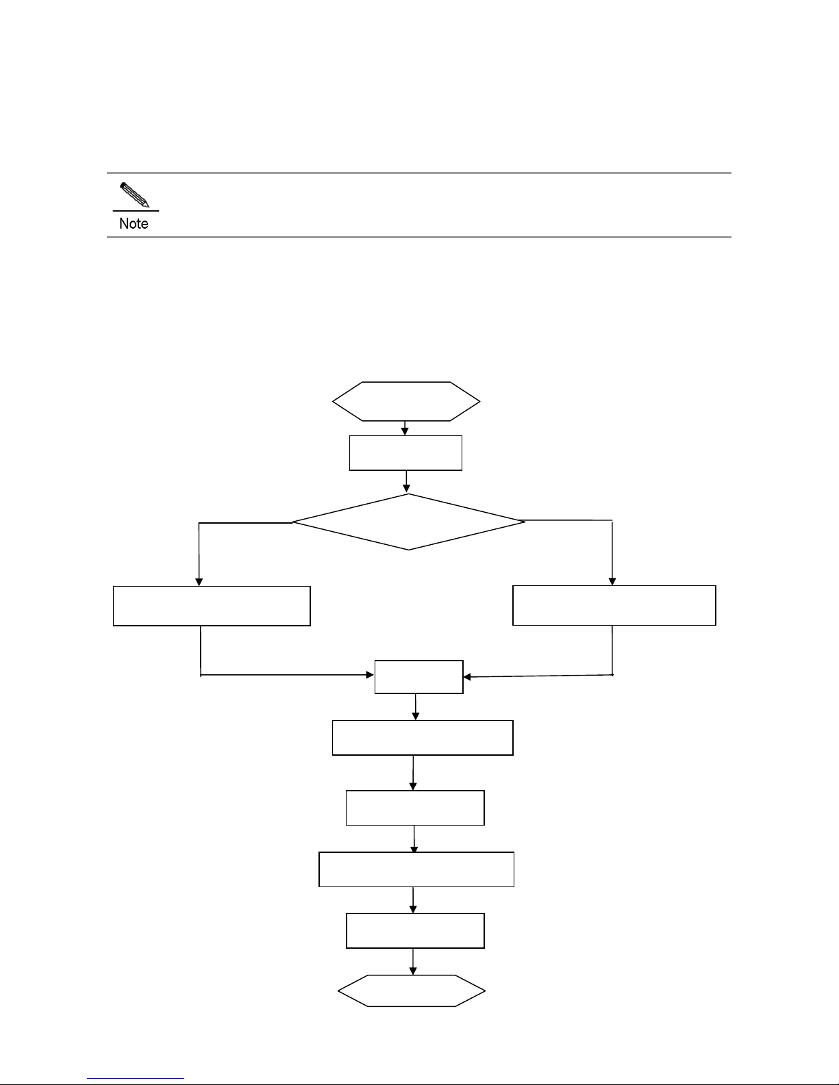
Installation Flowchart
Start
Check
Adjust Antenna Orientation
Install External Antenna(Optional)
Install Security Lock (Optional)
Connect Cables
Choose the Site
Install the Bracket on a Wall
Install the Bracket on a Pole
Install the AP
End

Before You Begin
Before you install the AP, verify that all the parts in the packing list are packed and make sure that:
The installation site meets temperature and humidity requirements.
The installation site is equipped with proper power supply.
Network cables are in place.
Precautions
The outdoor AP can be mounted on a wall (thickness: less than 2.5 mm) and a pole (diameter: 80 to 110mm). If the
diameter of the pole is out of the range, the hose clamp is customer-supplied. And the installation site varies with
on-the-spot surveys conducted by technical personnel.
Please make full preparation as described in Chapter 2 and observe the following precautions before you install the AP.
Before connecting the power supply, make sure the external power supply matches the power module inside the AP.
Before connecting the power cord, make sure the power switch is in the OFF position.
When connecting a wire to a binding post, make sure their colors are the same.
Make sure the power supply is properly connected.
Installing the AP
1) Attach the mounting plate to the bottom of the AP and fasten the plate with the supplied M8 x 20mm screws. See
Figure 3-1.
Figure 3-1 Fixing the Mounting Plate to the AP
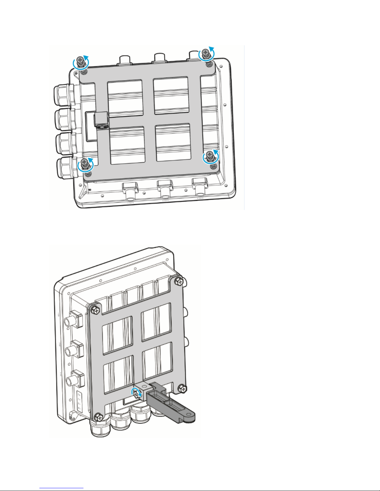
2) Attach the tie rod to the mounting plate and fasten the rod with the supplied M8 x 40 screws. See Figure 3-2
Figure 3-2 Fixing the Tie Rod on the Mounting Plate

Wall mount
3) Use the supplied cross-shaped bracket and M8 x 60 screws to implement the wall mount.
a. Attach the cross-shaped bracket to the wall and mark the screw hole locations. See figure 3-3.
Figure 3-3 Installing the M8 bolts
b. Hang the AP with the AP-side mounting bracket module to the cross-shaped bracket and tighten the M8×40 screws to
secure the AP. See figure 3-4.
Figure 3-1 Wall Mount
Vertical pole mount

a. Attach the cross-shaped bracket to a vertical pole with a hose clamp and fasten th e clamp with screws by using the
Phillips screwdriver.
F
igure 3-2 Fixing the Bracket on a Vertical Pole
b. Hang the AP with the AP-side mounting bracket module to the cross-shaped bracket and tighten the M8×40 screws to
secure the AP. See figure 3-6.
Figure 3-3 Installing the AP on a Vertical Pole
Horizontal pole mount

Figure 3-7 Fixing the Bracket on a Horizontal Pole
Figure 3-4 Installing the AP on the Horizontal Pole
similar as that of vertical mount. The procedure of horizontal pole mount is
Adjusting Antenna Orientation
Both directional and omni-directional anten
upper shell. To change the antenna orien
nas are available for RG-AP630. The integrated antenna is in parallel with the
tation, you should adjust the position of the mounting plate.
Figure 3-5 Anticlockwise Horizontal Rotation (-60°)
Directional Antenna Orientation

Figure 3-6 Clockwise Horizontal Rotation (+60°)
(-60°to +
60°horizontal rotation available)
Figure 3-7 Vertical Rotation (0°)

Figure 3-8 Clockwise Vertical Rotation (+60°)
(0°to 90° vertical rotation available)
Omni-directional Antenna Orientation
Figure 3-9 Anticlockwise Vertical Rotation (-90°)

Installing Security Lock (Optional)
The security lock is customer-supplied.
The lock loop on the AP is for your security needs. You can fasten the AP to a fixture as follows:
y lock to a fixture;
e lock loop.
1) Fasten the cable of a securit
2) Secure the lock plate into th
Figure 3-10 Lock Loop
ing cable is made on site. Connect the supplied grounding wire (yellow-green) to the AP grounding hole on
er end through OT terminals. To avoid waste, adjust the cable length on actual
Figure 3-11 Grounding the AP
Connecting Cables
Connecting the grounding cable
The ground
one end and ground the wire on the oth
demands.

Connecting the network cable
Waterproof material is customer-supplied.
1) Trim the network cable according to the
2) Thread the cable through liquid-tight ad
distance between the AP and the power supply.
apter and add a plug to the end. See figure 3-16.
Figure 3-12 Threading the Network Cable
yers of liquid-tight material. See figure 3-17. 3) Wrap the cable between B and C up with two or three la
Figure 3-13 Wrapping liquid-tight Material around Cable
In4) PoE IN port and tighten B, C and D in order. sert the plug into the
Make sure the plug is correctly inserted. The plug gets damaged when the liquid-tight adapter is wrenched
improperly.
t adapter first and then the plug. Before removing the network cable, dismantle the liquid-tigh

Installing Outdoor Antennas (Optional)
Outdoor antennas fall into directional and omni-directional antennas.
for special The integrated RG-AP630 antenna meets the demands in most cases. To obtain external antennas
occasions, go to http://www.ruijie.com.cn/.
Installing Outdoor Directional Antennas
To protect your outdoor directional antennas from lightning strikes, install a lightning rod on top of the pole.
block. Make sure the pole is exactly vertical
nless steel (40 mm x 4 mm).
ets. See Figure 3-12.
When installing the pole on the roof, install the pole on a wall or concrete
to ground.
To ground the antenna pole, connect the pole to a ground grid with a stai
Install the outdoor directional antenna to the pole with the supplied brack
Figure 3-18 Mounting the Outdoor Directional Antenna on the Pole
Installing O
y metal. Therefore, do not weld the lightning
tenna. Place the lightning rod in the middle of two
omni-directional antennas. See Figure 3-13.
When insta lling the antenna on the pole, make sure the top and bottom pole clamps are level to the ground and
parallel to each other.
utdoor Omni-directional Antennas
Omni-directional antennas must be kept at least one meter away from an
rod on the pole installed with an omni-directional an

Ensure the height of the antenna can provide desired signal
Ensure the top of the antenna is within the 45° protection ang
Figure 3-19 Mounting the Outdoor Omni-directional Antennas
coverage.
le.

Appendix A Connectors and Media
1000BASE-T/100BASE-TX/10BASE-T
The 1000BASE-T/100BASE-TX/10BASE-T is a 10/100/1000 Mbps auto-negotiation port that supports auto MDI/MDIX.
Compliant with IEEE 802.3ab, 1000BASE-T requires Category 5e 100-ohm UT P or STP (STP is recommended) with a
maximum distance of 100 meters (328 feet).
1000BASE-T requires all four pairs of wires be connected for data transmission, as shown in Figure A-1.
Figure A-1 1000BASE-T Connection
10BASE-T uses Category 3, 4, 5 100-ohm UTP/STP and 1000BASE-T uses Category 5 100-ohm UTP/STP for
connections. Both support a maximum length of 100 meters. Table A-1 shows 100BASE-TX/10BASE-T pin assignments.
Table A-1 100BASE-TX/10BASE-T Pin Assignments
Pin Socket Plug
1 Input Receive Data+ Output Transmit Data+
2 Input Receive Data- Output Transmit Data3 Output Transmit Data+ Input Receive Data+
6 Output Transmit Data- Input Receive Data4,5,7,8 Not Used Not Used
Figure A-2 shows wiring of straight-through and crossover cables for 100BASE-TX/10BASE-T.
Figure A-2 100BASE-TX/10BASE-T Connection

Fiber Connection
You can choose to use single mode or multi-mode fibers according to the transceiver m odule types. Figure A-3 shows
connection of fiber cables.
Figure A-3 Fiber Connection

Appendix B Mini-GBIC Module Specifications
Ruijie provides various Gigabit SFP transceivers (Mini-GBIC modules) for interfaces of wireless acces s controllers. You
can select the most suitable SFP modules as needed. This appen dix d escribes th e mod els and specifi cations of som e of
the Gigabit SFP transceivers for your reference.
Mini-GBIC (SFP) Models and Specifications
Table B-1 Models and Specifications of SFP Modules
Mini-GBIC(SFP)
Wave
lengt
h
(nm)
Fiber
Type
Core
Size
(micron)
Modal
Bandwidt
h
(MHz/km)
Cable
Distance
Max
Transmit
(dBm)
Max
Receive
(dBm)
Standards
FE-SFP-LX-MM
1310
1310 MMF
1
62.5/
125
— 2 km -14 -14
FE-SFP-LH15-S
M1310
1310 SMF
2
9/
125
— 15 km -8 -8
Mini-GBIC-SX 850 MMF1
62.5
62.5
50.0
50.0
160
200
400
500
220 m
275 m
500 m
550 m
-4
-17
Mini-GBIC-LX 1310
MMF
1
500
400
500
—
550 m
550 m
550 m
10 km
-3
-20
SMF
2
62.5
50.0
50.0
9/10
IEEE802.3
Mini-GBIC-LH40 1310 SMF
2
9/
125
— 40 km 3 -3
Mini-GBIC-ZX50 50 km 0 -22
Mini-GBIC-ZX80 80 km 4.7 -22
Mini-GBIC-ZX10
0
1550 SMF
2
— —
100 km 5 -9
Cat 5
Mini-GBIC-GT —
UTP
— — 100 m — —
1
MMF=Multimode fiber
2
SMF=Single mode fiber
W orter distances of single-mode fiber for optical SFP transceivers with cable distance greater than hen using sh
40 km (including 40 km), you may need to insert an in-line
optical attenuator in the link to avoid overloading
the receiver.

Appendix C 10-Year Hazardous Material Contents
Table C-1 Hazardous Material Contents Statements of Ruijie Products
Hazardous Material or Element
Parts Name
Plumbum
(Pb)
Mercury
(Hg)
Cadmium
(Cd)
Hexavalent
Chromium
(Cr(VI))
Polybrominate
d Biphenyl
(PBB)
Polybrominated
Diphenylethers
(PBDE)
PCBA
× ○ ○ ○ ○ ○
Other Electronic
Parts
× ○ ○ ○ ○ ○
Cables
× ○ ○ ○ ○ ○
Metal Parts
× ○ ○ ○ ○ ○
Plastic &
Polymeric Parts
○ ○ ○ ○ ○ ○
Battery
○ ○ ○ ○ ○ ○
○: Indicates that the contents of the poisonous hazardous substance in the component are less than the limit specified
in the SJ/T 11363-2006 standard.
X: Indicates that the contents of poisonous hazardous substance in at least one even materials of the component
exceed the limit specified in the SJ/T 11363-2006 standard.
Note:
This table lists the substances that may be included in Ruijie products. The preceding substances may not be included
in different models. Please check the contents of the actual model.
Except for special signs, the icon on the right is the mark of environment-friendly use period of
the product. The above use period is applicable to products only working in conditions as
stipulated in the product manual.
 Loading...