


RG-AP130(L) Series Access Point
Hardware Installation and Reference Guide V1.0

·
Copyright statement
Ruijie Networks©2017
Ruijie Networks reserves all copyrights of this document. Any reproduction, excerption, backup,
modification, transmission, translation or commercial use of this document or any portion of this document,
in any form or by any means, without the prior written consent of Ruijie Networks is prohibited.
Exemption statement
This document is provided “as is”. The contents of this document are subject to change without any notice.
Please obtain the latest information through the Ruijie Networks website. Ruijie Networks endeavors to
ensure content accuracy and will not shoulder any responsibility for losses and damages caused due to
content omissions, inaccuracies or errors.

·
Preface
Thank you for using our products. This manual will guide you through the installation of the access point.
Scope
It is intended for the users who have some experience in installing and maintaining network hardware. At the same time, it
is assumed that the users are already familiar with the related terms and concepts.
Obtaining Technical Assistance
Ruijie Networks Website: http://www.ruijienetworks.com/
Service Email: service_rj@ruijienetworks.com
Technical Support: http://www.ruijienetworks.com/service.aspx
Technical Support Hotline: +86-4008-111-000
Related Documents
Documents
Description
Configuration Guide
Describes network protocols and related mechanisms that supported by the
product, with configuration examples.
Command Reference
Describes the related configuration commands, including command modes,
parameter descriptions, usage guides, and related examples.
Documentation Conventions
The symbols used in this document are described as below:
This symbol brings your attention to some helpful suggestions and references.
This symbol means that you must be extremely careful not to do some things that may damage the device or cause
data loss.

·
Hardware Installation and Reference Guide Product Overview
1 Product Overview
Ruijie RG-AP130(L) Wall AP is designed for wireless deployment in hotels, offices, residential buildings and settings alike.
The wall-mountable AP has the same size as a standard 86-type faceplate with integrated Ethernet and VoIP ports.
Featuring a concise design and easy deployment, the AP enables zero disruption to the interior finishes and offers the
best solution for scenarios with delicate interior design.
The dual-radio, dual-band AP supports concurrent operation of 802.11a/n/ac and 802.11b/g/n, delivering data rates of up
to 300Mbps in 802.11n and 866Mbps in 802.11ac. The Wall AP provides four 10/100/1000Base-T LAN ports and one
10/100/1000Base-T WAN port, delivering optimal wireless network coverage and cost protection with additional wired
network interfaces and VoIP ports.
RG-AP130(L) supports security, radio frequency (RF) control, mobile access, Quality of Service (QoS) and seamless
roaming. Teaming up with Ruijie RG-WS Wireless Controller Series, wireless data forwarding, high performance security
and access control can be accomplished with ease.
1.1 Technical Specifications
Table 1-1 Technical Specifications of RG-AP130(L)
Hardware Specifications
Radio
2.4G: 2 x 2MIMO
5G: 2 x 2MIMO
Transmission
Protocol
2.4G : 802.11b/g/n
5G : 802.11a/n/ac
Operating Bands
802.11b/g/n: 2.4 GHz to 2.4835 GHz
802.11a/n/ac: 5G: 5.15 GHz to 5.35 GHz, 5.47 GHz to 5.725 GHz, 5.725 GHz to 5.85GHz
(Country-specific)
Antenna
Built-in low-radiation omnidirectional antenna (Base gain 3dBi)
Spatial Streams
2 streams
Max Throughput
802.11b/g/n: up to 300Mbps
802.11a/n/ac: up to 867Mbps
Up to 1.167Gbps per AP
Modulation
OFDM: BPSK@6/9Mbps, QPSK@12/18Mbps, 16-QAM@24Mbps, 64-QAM@48/54Mbps
DSSS: DBPSK@1Mbps, DQPSK@2Mbps, and CCK@5.5/11Mbps
MIMO-OFDM: BPSK, QPSK, 16QAM , 64QAM and 256QAM
Receive Sensitivity
11b/g: -94dBm(1Mbps), -74dBm(54Mbps)
11a: -90dBm(6Mbps), -74dBm( 54Mbps)
11nHT20: -72dBm@MCS7, -68dBm@MCS15
11ac HT20: -90dBm( MCS0) , -65dBm( MCS8)
11ac HT40: -85dBm( MCS0) , -60dBm( MCS9)
11ac HT80: -82dBm( MCS0) , -58dBm( MCS9)
Max Transmit Power
≤100mw (20dBm, RF card transmit power only)
(Depending on the country of use, laws and regulations.)

·
Hardware Installation and Reference Guide Product Overview
Transmit Power
Adjustment
1 dBm
Dimensions
(W x D x H)
116mm x 86mm x 42mm
Weight
0.23kg
Service Ports
Front:
Four 10/100Base-T LAN ports
Side:
1 RJ-45 Voice/PoE pass-through port (RJ-11 combo)
Rear:
One 10/100/1000Base-T WAN port
1 RJ-45 Voice/PoE pass-through port (RJ-11 combo)
Management Ports
1 Micro USB port for console management (hidden)
LED Indicators
Indicator for AP, Ethernet and wireless status
Power Supply
PoE: IEEE 802.3af/802.3at-compliant (compatible).
Power Consumption
≤8W
Temperature
Operating: -10 to 45°C (14 to 113°F)
Storage: -40 to 70°C (-40 to 158°F)
Humidity
Operating: 10% to 95% (non-condensing)
Storage: 5% to 95% (non-condensing)
Installation
Ceiling/wall mount in a 86-type faceplate
IP Rating
IP41
Safety Standards
GB4943
EN/IEC 60950-1
EMC Standards
IEC61373
GB9254
EN301489
EN50121
EN50155
Vibration
China Radio Transmission Equipment Type Approval Certificate
EN300 328
EN301 893
Radio
China Radio Transmission Equipment Type Approval Certificate
EN300 328
EN301 893
MTBF
>250,000H
Software Functions
Security
Data encryption
Support
Frame Filtering
WPA(TKIP), WPA2 (AES), WPA-PSK, WEP
(64 or 128 bits) and WAPI (hardware)
User isolation
Whitelist
Static blacklist
Dynamic blacklist

·
Hardware Installation and Reference Guide Product Overview
Rogue AP detection and countermeasure
Support
Dynamic ACL assignment
Support
RADIUS
Support
CPU Protection Policy (CPP)
Support
Network Foundation Protection Policy (NFPP)
Support
Routing
IPv4 address
Support
IPv6 CAPWAP tunnel
Static IP address or DHCP
ICMPv6
Support
IPv6 address
Support
IPv6 tunnel
Not Supported
ISATAP
Not Supported
Multicast
Multicast to unicast conversion
Network management
SNMP v1/v2C/v3, Telnet, TFTP, and FTP and
Web management
Management and
Maintenance
Fault detection and alarm
Support
Statistics and logs
Support
FAT/FIT switchover
Support
1.2 Product Image
The AP provides two built-in radio ports, one 10/100/1000Base-T Ethernet WAN port, and four 10/100Base-T Ethernet
LAN ports.
Figure 1-1 Image of RG-AP130(L)
PoE/UpLNK port, the yellow port, is the 10/100/1000Base-T WAN port (PoE-capable).
Pass Through port, the blue port, and its equivalence on the side are straightly connected.
Figure 1-2 Side View of RG-AP130(L)

·
Hardware Installation and Reference Guide Product Overview
Note
1. Reset button
2. Lock Slot
3. Micro USB management port (Console)
4. Keyhole
5. Pass Through port on the side
1.3 LED Indicators
Figure 1-3 Indicator on the AP
State
Frequency
Meaning
Off
N/A
The AP is powered off. Or the AP is in Silent mode.
Fast blinking
green before
solid green
2.5Hz (fast
blinking green)
Initialization is in progress. The AP is operational.

·
Hardware Installation and Reference Guide Preparing for Installation
Fast blinking red
2.5Hz
Firmware upgrade in progress. Do not power off the AP.
Blinking orange
1Hz
AP is operational and Ethernet link is down.
Blinking green
1Hz
AP is operational and Ethernet link is up. CAPWAP error.
Slow blinking
green
0.4Hz
AP is operational and CAPWAP connection is established. At least one client is
associated.
1.4 Power Sources
The AP is powered through Power over Ethernet (PoE). To use a PoE device, make sure it supports the IEEE 802.3af
PoE standard.
Input voltage range: 44-57V
Rated current: 0.25A
When powered through PoE, the AP can be used with Ruijie’s other products supporting 802.3af PoE.
1.5 Cooling Solution
The AP adopts fanless design. Because it is installed in an 86-style faceplate on the wall, to guarantee airflow for proper
ventilation, keep the device uncovered.
2 Preparing for Installation
2.1 Safety Suggestions
RG-AP130(L) must be used inside the room. To ensure normal operation and a prolonged useful life of the equipment, the
installation site must meet the following requirements.
To prevent device damage and bodily injury, please read carefully the safety recommendations described in this chapter.
The recommendations do not cover all possible hazardous situations.
2.2 Installation
Do not expose the AP to high temperature, dusts, or harmful gases.
Do not install the AP in an inflammable or explosive environment.
Keep the AP away from EMI sources such as large radar stations, radio stations, and substations.
Do not subject the AP to unstable voltage, vibration, and noises.
Keep the installation site dry. Installing the device near sea is not recommended.
Keep the AP at least 500 meters away from the seaside and do not face it toward the wind from the sea.
The installation site should be free from water flooding, seepage, dripping, or condensation.

·
Hardware Installation and Reference Guide Preparing for Installation
The installation site shall be selected according to network planning and features of communications equipment, and
considerations such as climate, hydrology, geology, earthquake, electric power, and transportation.
2.3 Temperature and Humidity
Required temperature and humidity are as follows:
Operating temperature: -10°C ~ 45°C (14°F to 113°F)
Storage temperature: -40°C ~ 70°C (-40°F to 158°F)
Operating humidity: 10%~95% (non-condensing)
2.4 Cleanness
Dust poses a serious threat to device operation. Dust that falls onto the surface of the device can be absorbed onto metal
contact points by static electricity, resulting in poor contact. Electrostatic absorption of dust occurs more easily when the
relative humidity is low, which may shorten the service life of the device and cause communication failures. Table 2-2
shows the maximum concentration and diameter of dust allowed in the equipment room.
Table 2-1
Maximum diameter (μm)
0.5
1
3
5
Maximum concentration
(Particles/m3)
1.4 x 10
7 x 10
2.4 x 10
1.3 x 10
Besides, the contents of salts, acids and sulfides in the air are also strictly limited for the equipment room. These
substances can accelerate metal corrosion and the aging of some parts. Table 2-3 describes the limit of some hazardous
gases such as SO2, H2S, NO2 and Cl2 in the equipment room.
Table 2-2
Gas
Average (mg/m3)
Maximum (mg/m3)
SO2
0.2
1.5
H2S
0.006
0.03
NO2
0.04
0.15
NH3
0.05
0.15
Cl2
0.01
0.3
2.5 EMI Consideration
Various interference sources, from either outside or inside the equipment or application system, affect the system in the
conductive ways such as capacitive coupling, inductive coupling, and electromagnetic radiation. There are two types of
electromagnetic interferences: radiated interference and conducted interference, depending on the type of the
propagation path. When the energy, often RF energy, from a component arrives at a sensitive component via the space,
the energy is known as radiated interference. The interference source can be both a part of the interfered system and a
completely electrically isolated unit. Conducted interference results from the electromagnetic wire or signal cable
connection between the source and the sensitive component, along the cable the interference conducts from one unit to

·
Hardware Installation and Reference Guide Installing the Access Point
another. Conducted interference often affects the power supply of the equipment, but can be controlled by a filter.
Radiated interference may affect any signal path in the equipment, and is difficult to shield.
Effective measures should be taken for the power system to prevent the interference from the electric grid.
The working ground of the routers should be properly separated and kept as far as possible from the grounding
device of the power equipment or the anti-lightning grounding device.
Keep the equipment away from high-power radio transmitter, radar transmitting station, and high-frequency
large-current device.
Measures must be taken to isolate static electricity.
2.6 Installation Tools
Common Tools
Phillips screwdriver, straight screwdriver, related copper and fiber cables, bolts, diagonal pliers,
cable ties
Special Tools
Anti-static tools
Meter
Multimeter
The listed tools, apart from bolts, are customer supplied.
3 Installing the Access Point
Make sure you have carefully read Chapter 2, and be sure that the requirements set forth in Chapter 2 have been
met.

·
Hardware Installation and Reference Guide Installing the Access Point
3.1 Installation Flowchart
3.2 Before You Begin
To ensure normal operation and a prolonged useful life of the equipment, observe the following safety precautions:
Install the device in a well-ventilated location.
Do not subject the device to high temperatures.
Keep away from high voltage cables.
Install the device indoors.
Do not expose the device in a thunderstorm or strong electric field.
Keep the device clean and dust-free.
Disconnect the device before cleaning it.
Do not wipe the device with a damp cloth.
Do not wash the device with liquid.
·
Hardware Installation and Reference Guide Installing the Access Point
Do not open the enclosure when the AP is working.
Fasten the device tightly.
3.3 Installing the Access Point
Disconnect the device before install or move it.
Make sure that the screws are of fine quality.
Be sure that the equipment is installed in a place where it is easy to be observed.
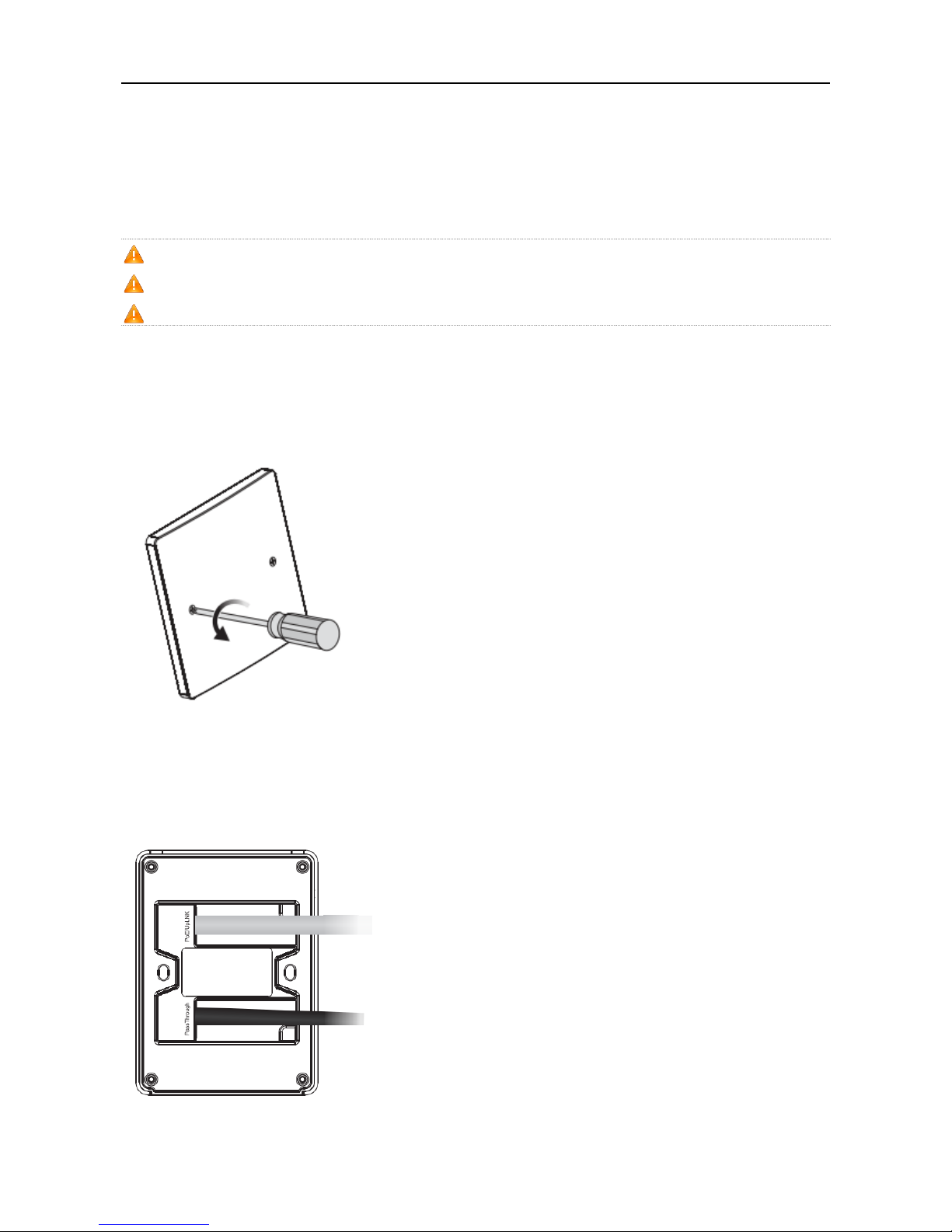
1) Loosen screws on the 86-type faceplate that is mounted on the wall. (Skip this step if the faceplate has not been
mounted.)
Figure 3-1 Loosen Screws on the Faceplate
2) Connect the uplink cable to the UpLNK port. The cable connected to Pass Through port can be a telephone line or
any cable based on user’s need.
Figure 3-2 Connect Cables to Ports
·
Hardware Installation and Reference Guide Installing the Access Point
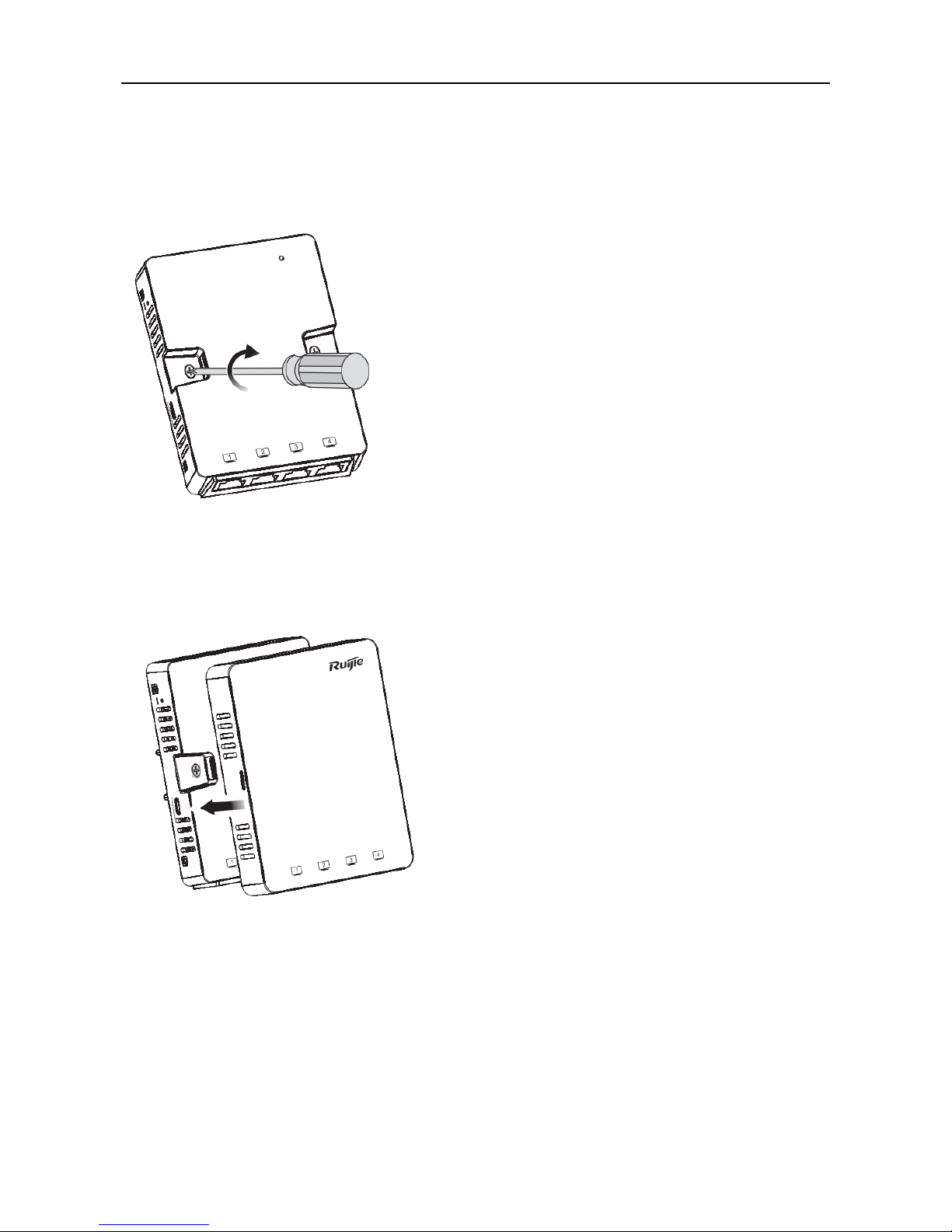
3) Align screw holes on both sides of the device over those on the faceplate. And then tighten screws with a
screwdriver.
Figure 3-3 Tighten Screws with a Screwdriver
4) Install the plate cover in the way as shown in the following figure.
Figure 3-4 Install the Cover
A white cover is provided for each AP. And there are three more options for sale: black, gold and silver.
Figure 3-5 Cover for RG-AP130(L)

·
Hardware Installation and Reference Guide System Debugging
4 System Debugging
4.1 Setting up a Debugging Environment
Use PoE to power the AP.
PoE power supply
To use a PoE device, make sure the peer end supports the IEEE 802.3af PoE standard. Then, connect the Ethernet cable
to the uplink port (WAN) on the AP.
Figure 4-1 Connect the Ethernet Cable to the UpLNK Port
DC power adapter power supply
DC power adapter supply is not supported on RG-AP130(L).
4.1.1 Powering Up the AP
4.1.1.1 Checking before power-up
Verify that the input voltage matches the specification of the AP.

·
Hardware Installation and Reference Guide System Debugging
4.1.1.2 Checking after power-up
After powering up, it is recommended that you check the following items to ensure normal operation of the AP.
The LED on a normally-working AP gets blinking green first. After 60s, the LED turns solid green.
Figure 4-2 LED on the AP
4.1.2 Reset/Restore Default Settings
The reset button is hidden in a hole and used by technical support personnel. To avoid abnormal operation, do not use
this button without consultation with technical support personnel.
Figure 4-3 Reset Button on the AP
4.1.3 System Reset
Remove the cover. Insert an iron stick, 1mm or less in diameter, into the hole, and slightly press it. After hearing a click,
keep the stick in the same position for 2s. The system reset is complete.
4.1.4 Restore Default Settings
Remove the cover. Insert an iron stick, 1mm or less in diameter, into the hole, and slightly press it. After hearing a click,
keep the stick in the same position for 3s. The system reset is complete.

·
Hardware Installation and Reference Guide Monitoring and Maintenance
5 Monitoring and Maintenance
5.1 Monitoring
You can observe the LED to monitor the AP in operation.
Fast blinking green followed by solid green: The AP is being initialized and is operational.
Blinking red: The AP is upgrading programs firmware. Do not power off the AP.
Blinking orange: The AP is operational. The Ethernet link is down.
Blinking green (1Hz): The AP is operational, and the Ethernet link is up. But the CAPWAP connection is faulty.
Blinking green (0.4Hz): The AP is operational. The CAPWAP connection is OK. At least one client is associated with
the AP.
Blinking green (one flash every 4 seconds): The AP is operational. No clients are associated with the AP. The
system is in the low consumption mode.
5.2 Remote Maintenance
If the AP operates as a Fit AP, you can use AC to manage and maintain the AP.
5.3 Installation and Removal
Guide for installing and removing RG-AP130(L) is included in Chapter 3.3 Installing the Access Point.
Before removing the AP, please make sure:
1. it is powered off.
2. the lock is removed.
The surface of the cover plays a major role in dissipating heat, so its temperature is higher than environment
temperature.

·
Hardware Installation and Reference Guide Troubleshooting
6 Troubleshooting
6.1 Troubleshooting Flowchart
6.2 Troubleshooting
LED does not light up after the AP is powered on
Verify that the power source is IEEE 802.11af compliant. And then verify that the cable is connected properly.
Orange LED blinks after the Ethernet cable is connected
Verify that the device at the other end of the Ethernet cable is working properly. And then verify that the Ethernet cable is
capable of providing the required data rate and is properly connected.
Wireless client cannot find the AP
1) Follow the above-mentioned two steps.
2) Verify that the AP is configured correctly.
3) Adjust the transmit power.
4) Move the client device to adjust the distance between the client and the AP.
The installation instruction above is based on RG-AP130(L). The actual product prevails.

·
Hardware Installation and Reference Guide Appendix A Connectors and Media
Appendix A Connectors and Media
1000BASE-T/100BASE-TX/10BASE-T
The 1000BASE-T/100BASE-TX/10BASE-T is a 10/100/1000 Mbps auto-negotiation port that supports auto MDI/MDIX.
Compliant with IEEE 802.3ab, 1000BASE-T requires Category 5e 100-ohm UTP or STP (STP is recommended) with a
maximum distance of 100 meters (328 feet).
1000BASE-T requires all four pairs of wires be connected for data transmission, as shown in Figure A-1.
Figure A-1 1000BASE-T Connection
10BASE-T uses Category 3, 4, 5 100-ohm UTP/STP and 1000BASE-T uses Category 5 100-ohm UTP/STP for
connections. Both support a maximum length of 100 meters. Table A-1 shows 100BASE-TX/10BASE-T pin assignments.
Table A-1 100BASE-TX/10BASE-T Pin Assignments
Figure A-2 shows wiring of straight-through and crossover cables for 100BASE-TX/10BASE-T.
Figure A-2 100BASE-TX/10BASE-T Connection
 Loading...