

Page 1

1
Operating Manual
for
the semi automatic
High-Tech-Cutter
SR1 and SR1 turbo
Rühle GmbH Lebensmitteltechnik
Beim Signauer Schachen 10
79865 Grafenhausen
Tel: ++49 7748 - 523-0
Fax: ++49 7748 - 52385-00
10/2001 CR www. Ruhle.biz
M
anual
Us
er
SR 1
(tur
b
o)
Page 2

2
Contents Page
1. Safety instructions ...........................................................................................................................................3
1.1 Safety hints..........................................................................................................................................................3
1.2 Safety data sheet.............................................................................................................................................4
2. Installation instructions ................................................................................................................................6
2.1 Machine installation................................................................................................................................... .7
2.2 Connection of the Machine.......................................................................................................................7
2.3 Commissioning of the machine................................................................................................................8
3. Operating instructions ...............................................................................................................................9
3.1 Switching on the machine..........................................................................................................................9
3.2 Cutting preparation....................................................................................................................................10
3.3 Cut adjustments. ..........................................................................................................................................10
3.4 The HighTech-cutter..................................................................................................................................16
3.4.1 HighTech-cutter selection..........................................................................................................................17
3.4.2 HighTech-cutter assembly........................................................................................................................17
3.4.3 HighTech-cutter installation.....................................................................................................................19
3.4.4 HighTech-cutter maintenance................................................................................................................20
3.5 The sectioning Blade................................................................................................................................20
3.6 The Tool box................................................................................................................................................21
3.7 Feeding the machine...............................................................................................................................22
3.7.1 The work bench............................................................................................................................................22
3.7.2 The shaft – charging..................................................................................................................................22
3.8 Product discharge.......................................................................................................................................23
3.8.1 The use of boxes........................................................................................................................................23
4. Cleaning instructions.................................................................................................................................24
4.1 Safety hints.....................................................................................................................................................24
4.2 Cleaning agents and disinfectants...................................................................................................24
4.2 Cleaning procedure...................................................................................................................................25
5. Technical service........................................................................................................................................26
5.1 Regular maintenanace...........................................................................................................................26
5.2 Regular servicing........................................................................................................................................27
5.3 Errors ...............................................................................................................................................................28
6. Technical documentation...............................................................................................29
6.1 Circuit diagrams.........................................................................................................................................29
6.2 List of spare parts.....................................................................................................................................29
7. Index............................................................................................................................................................30
Page 3

3
1. Safety Instructions
!!! The safety instructions have to be observed during the installation, operation, cleaning and
servicing of the Rühle High Tech Cutter type SR 1 and SR1 turbo.
1.1 Safety hints
!!! The operating manual has to be read by the supervising personal before installation, operation,
cleaning or servicing. The supervising personal has to make sure, that the operator as well as
the persons cleaning and servicing the machine, have read and understood the operating
manual.
!!! The operator has to operate the machine as directed and strictly pay attention to all points of the
operating manual. The supervisor has to write an instruction for the intended use of the
machine.
!!! Before starting up the machine, the operator has to check the functionality of the following
safety devices on a day to day basis:
A. Visual control on all sides of the machine for changes or damage. In
case of changes or damage, the machine has to be shut down.
B. Close the door to the cutting area – lock discharge funnel inside the cutting area
door – start the machine – open the cutting area door 20 mm. Should the machine
not stop it has to be shut down immediately.
C. Close the door to the cutting area – close process shaft – start the machine – open
the process shaft. If the machine doesn’t stop, it has to be shut down immediately.
D. Lock the brakes of the casters at the back. – Try to move the machine by pushing
it. – Select a different location if the machine moves and shut the machine down
immediatly should the new location result in movement again
To shut down the machine, the main switch has to be turned to position”0”. Additionaly, the
main switch has to be secured by a pad lock. The key has to be handed over to the
supervisor. The mains plug has to be disconnected from the power outlet.
!!! The supervising personal has to make sure, that the malfunctioning safety devices
are repaired by a Rühle technician. It’s the supervisors responsibility, that the machine isn’t
used under any circumstances until the repairs have been carried out.
!!! The cleaning personal has to observe the cleaning instructions.
The supervisor has to write instructions for a safe cleaning procedure.
!!! The maintenance personal is only allowed to service the machine within the guidelines of
”regular maintenance 5.1” unless written permission has been given by the manufacturer
to do otherwise. The supervisor has to write instructions for safe maintenance works.
Page 4

4
!!! It’s not allowed to modify the machine.
!!! The supervisor has to make sure, that the functionality of the safety devices is checked every
2000 working hours, but at least once a year by a Rühle service technician.
!!! Only Rühle spare parts and accessories are allowed to be used.
!!! The resale of the machine includes the handing-over of the complete operating manual.
1.2 Safety data sheet
The feeder shaft lock, the product discharge, the box and lifting system as well as the electronic
equipment correspond to the draft of the European Standard pr EN XXX
”Cutting machines for cubes”, edition 3/1998.
This machine is not fitted with an emergency-STOP device, because there is no risk for the
operator and the product. The OFF-sensor on the operating panel is within easy reach from the
operating area.
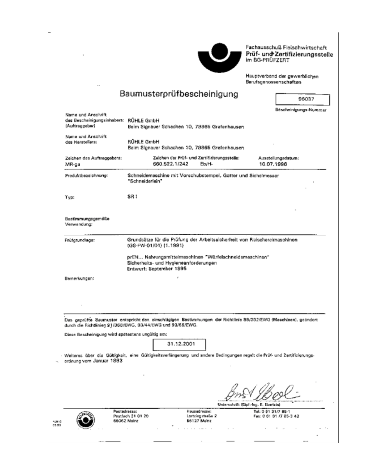
CE – Conformity declaration
The fully automatic High-Tech-Cutter of the Type SR1 and SR 1 turbo corresponds to the following
safety and health requirements:
a. EU – Machine guideline 89 / 392 / EWG and 91 / 368 / EWG
b. prEN 1672-2: 1992 Food machines, safety and hygiene requirements
Part 2: Hygiene requirements February 1995
c. EN 60204-1: Electrical equipment of machines
Part 1: General regulations
d. Rühle - Documentation
Claus Rühle
Geschäftsführer
Page 5
5
Page 6
6
2. Installation instruction
Installation and commissioning of the machine should only be carried out in presence of
a Rühle service technician.
The Rühle limited liability company is not liable for damages caused by violation of these
instructions.
The transport of the machine has to be carried out according to the operating manual.
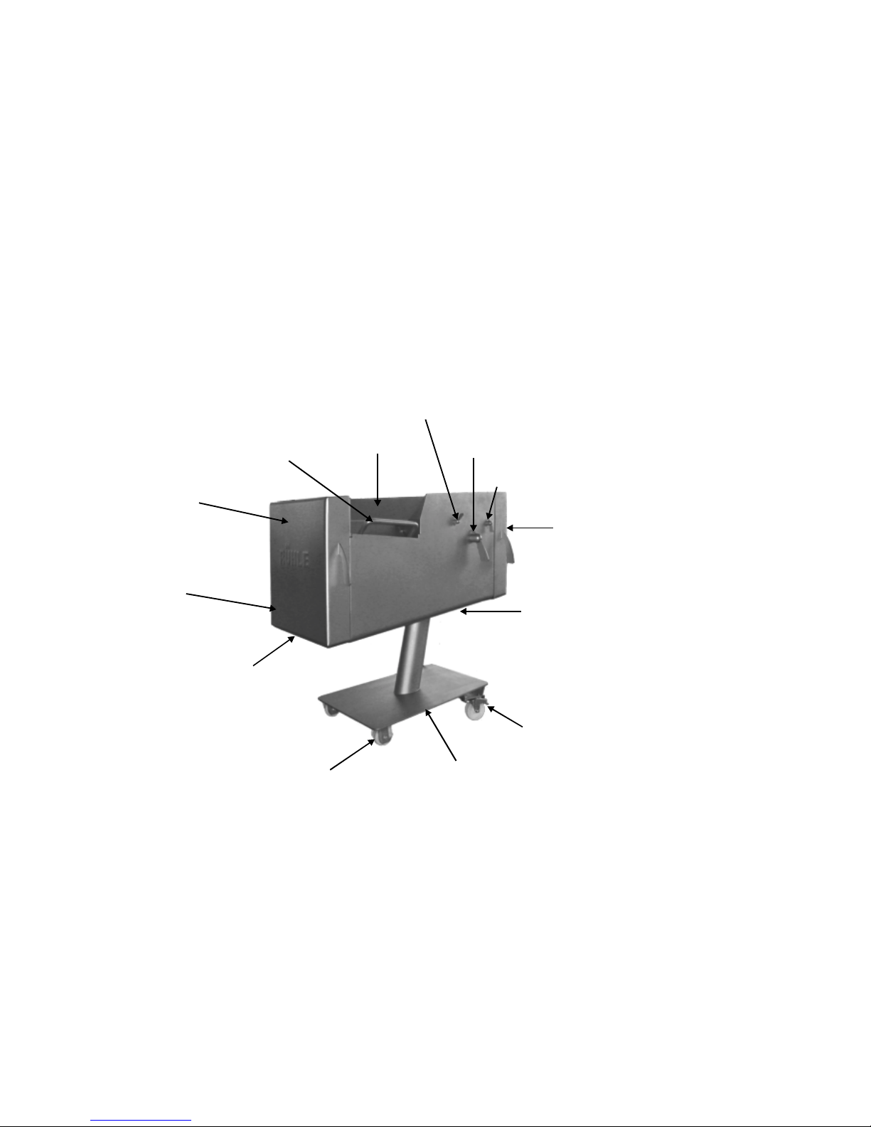
Main switch
Cutting length
adjus tment lever
Pre-compacting
adjus tment lever
Work ben ch
Tool box
Maintenance door
Steering roller with
locking brake
Singl e foot un d e r ca rriage
Caster
Product
discharge
Discharge
funnel
Cutting area door
Fastening sliderprocess chamber
Page 7
7
2.1 Machine installation
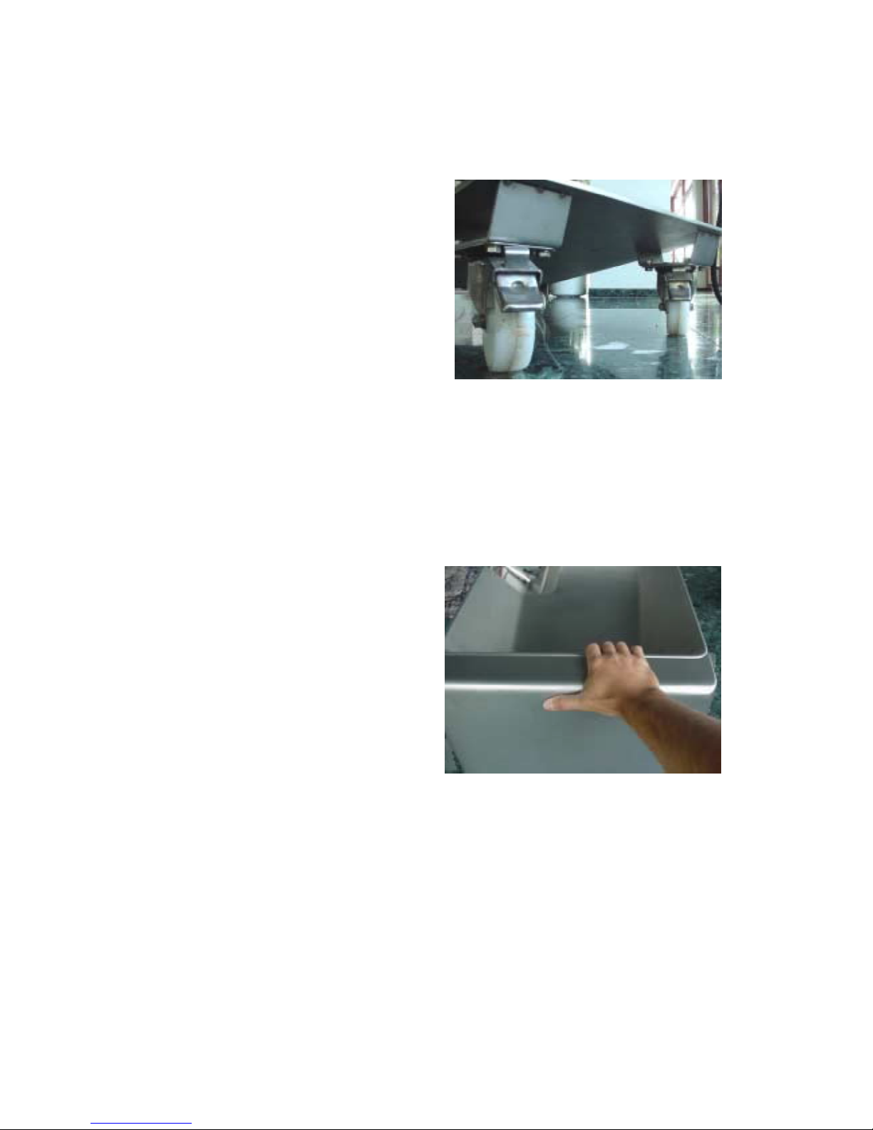
For the transport and delivery the machine is equipped with two casters at the front and two
steering rollers with a locking brake each at the back.
For a safe transport the brakes have to be
unlocked. The operator moves the machine
in the desired direction by pushing and
steering it from the back with the hands holding
on to back with the hands holding on to
the top.
No persons or objekts should be near or in
front of the machine during transport.
During the installation and transport of the machine see to it that the floor can withstand a
load of 400 Kg/m². The machine has to be positioned in such a way that a passable safety path
of one meter in width is all around the machine.
No objects, which could change the centre of gravity or the total weight should be lying on the
machine during transport.
The two locking brakes have to be
engaged once the desired process
location has been reached.
Check the structure and the slope of the
floor in order to guarantee a save position
of the machine.
The machine has to be positioned in such a way, that there is an unrestricted ceiling height of at
least 2,30 m so that the operator has an unrestricted working area above the machine.
2.2 Connection of the machine
Before connecting the machine to the mains, make sure that the power outlet is dimensioned
according to the machine datas. The High-Tech-Cutter SR1 and SR1 turbo is standard equipped
with a connected load of 400 V / 50 Hz / 16 A / 1,5 kW.
Page 8
8
These values can vary, so take the values from
the data plate, positioned at the back of the
machine, before finally connecting the machine.
After an electrician has fitted a suitable power
plug to the power lead, the machine can be supplied
with power by connecting the lead to the power
point.
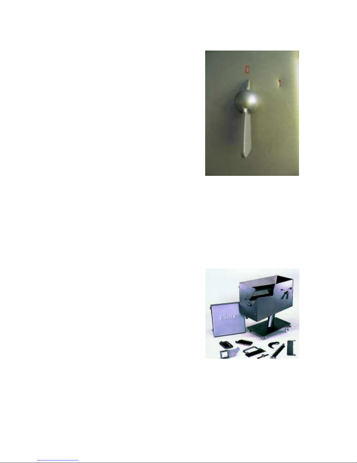
Turn the main switch from ”0” to ”1” to turn on
the machine.
Should it be impossible to start the machine
despite locking all safety devices, then the
rotang field has to be changed by an electrician
by changing over the two black leads inside
the power plug.
2.3 Commissioning of the machine
The operating manual has to be read and understood before commissioning the machine.
This is followed by cleaning and disinfecting of the machine according to the cleaning
instructions.
All accessories have to be checked for visible damage – a possible cause of the transport –
during the cleaning process. The same applies for the entire machine, especially the safety
devices
Switch ON the machine by turning the main
switch to „1“. Open the tool box.
Now clean and disinfect the entire tool box
according to the cleaning instruction.
Now clean and disinfect all HighTech-cutters and
hang them into the tool box.
Now the main switch has to be turned to ”0” so that the Rühle technician can activate the six
Self-lubricating systems inside the machine.
After turning the machine on the main switch on again, the first test-run can be carried out,
by selecting the desired cutting program and inserting the relevant Multi-cutter into the machine.
Page 9
9
3. Operating instructions
3.1 Switching on the machine
To start the machine......
......the main switch has to be turned to position ”1”
......a trolley with a box has to be pushed under the cutting area door.
........the discharge funnel has to be installed inside the cutting area door.
......with a Multi-cutter installed, the shaft slider and the
cutting area door have to be closed.
......The ”ON” key on the operating panel has to be
activated.
Now the machine can be started, provided, that the Multi-cutter, prescribed in the
cutting program, has been inserted.
3.2 Cutting preperation
The machine has to be adjusted to the product prior to the cutting process.
The adjustment consist of inserting the correct multi grid combination, choosing
The right cutting length (forward feed length) and the best pre-compacting
Pressure. Pre-compacting has the funktion to press the product into a compact
Block inside the process chamber before the actual cutting process. Each product
Can only sustain a certain amount of pressure without beeing damaged.
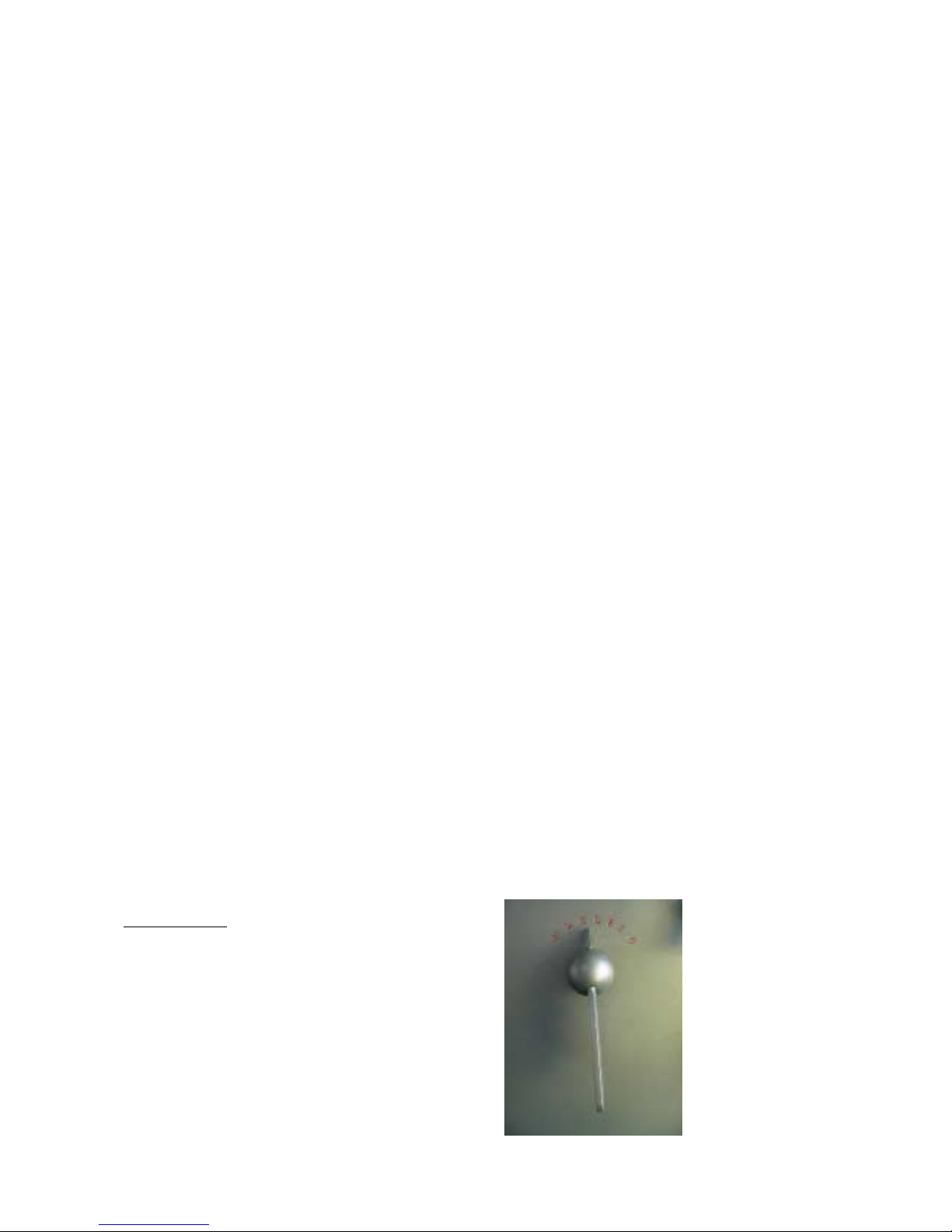
Cutting Length:
With the forward feed adjusting lever it is
possible to choose cutting lengths between
1 mm and 30 mm.
To adjust the length the lever has to be
pulled away from the machine and turned
to the desired position.
Releasing the lever lets it slide back on to the
machine again.
Page 10
10
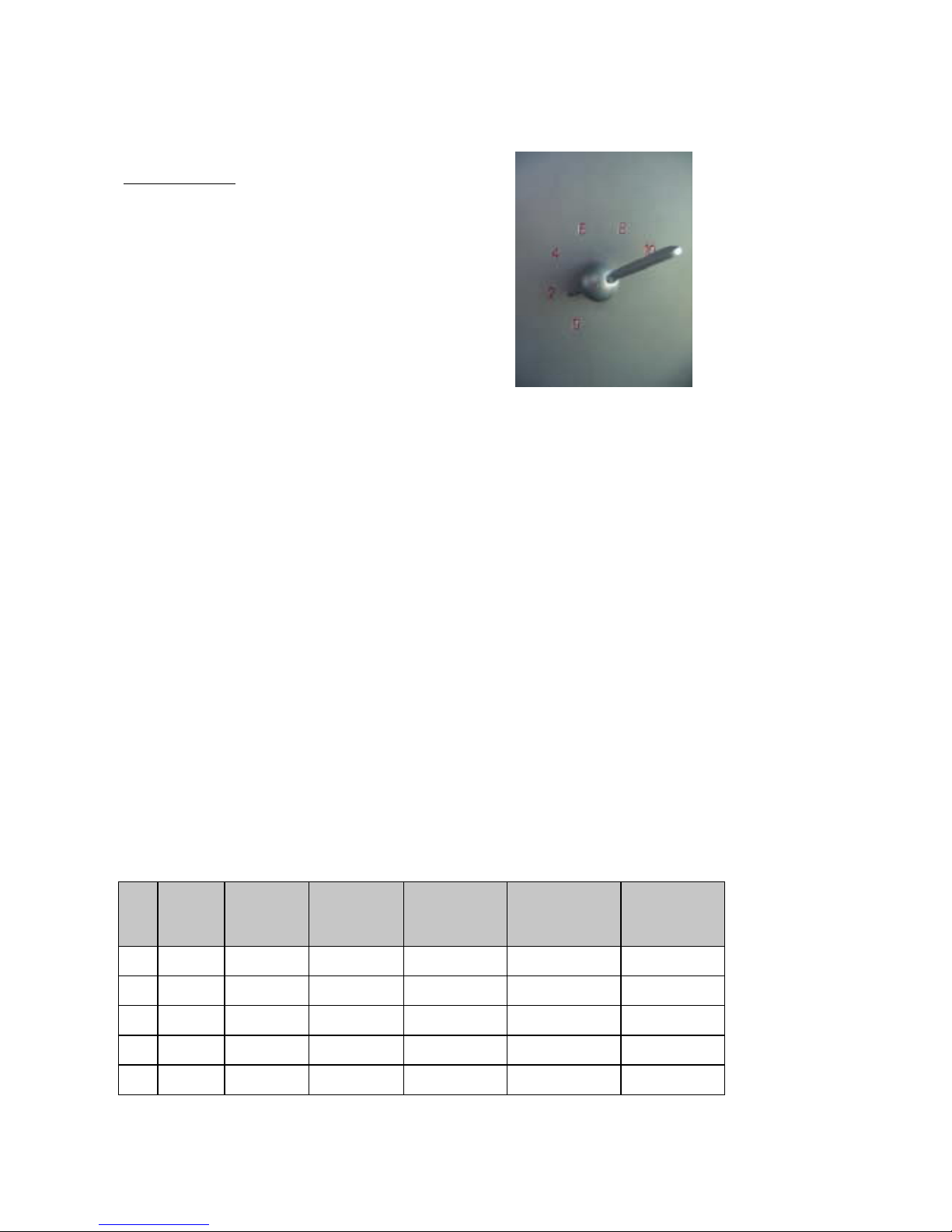
Pre-compacting:
A simple rotary motion brings the
pre-compacting adjusting lever to the
desired position
from 0
( no compacting Presure )
to 10
( highest compacting pressure )
3.3 Cut adjustments
To vary pre-set cutting parameters it requires a great deal of cutting experience as well as a sound
knowledge of the machine in order to achieve the best cutting result without the machine suffering
any damage.
That’s why a variation of pre-set cutting parameters should only be changed after a written
confirmation by the Rühle GmbH. The best product adjustment is achieved with the help of a
Rühle service technician.
There is a choice of different adjustment variables for each product, taking different cut-sizes and
different cut goods into consideration.
It has to be considered however, that only those produkt parameter combinations can be used, for
which the HighTech-cutter has been supplied.
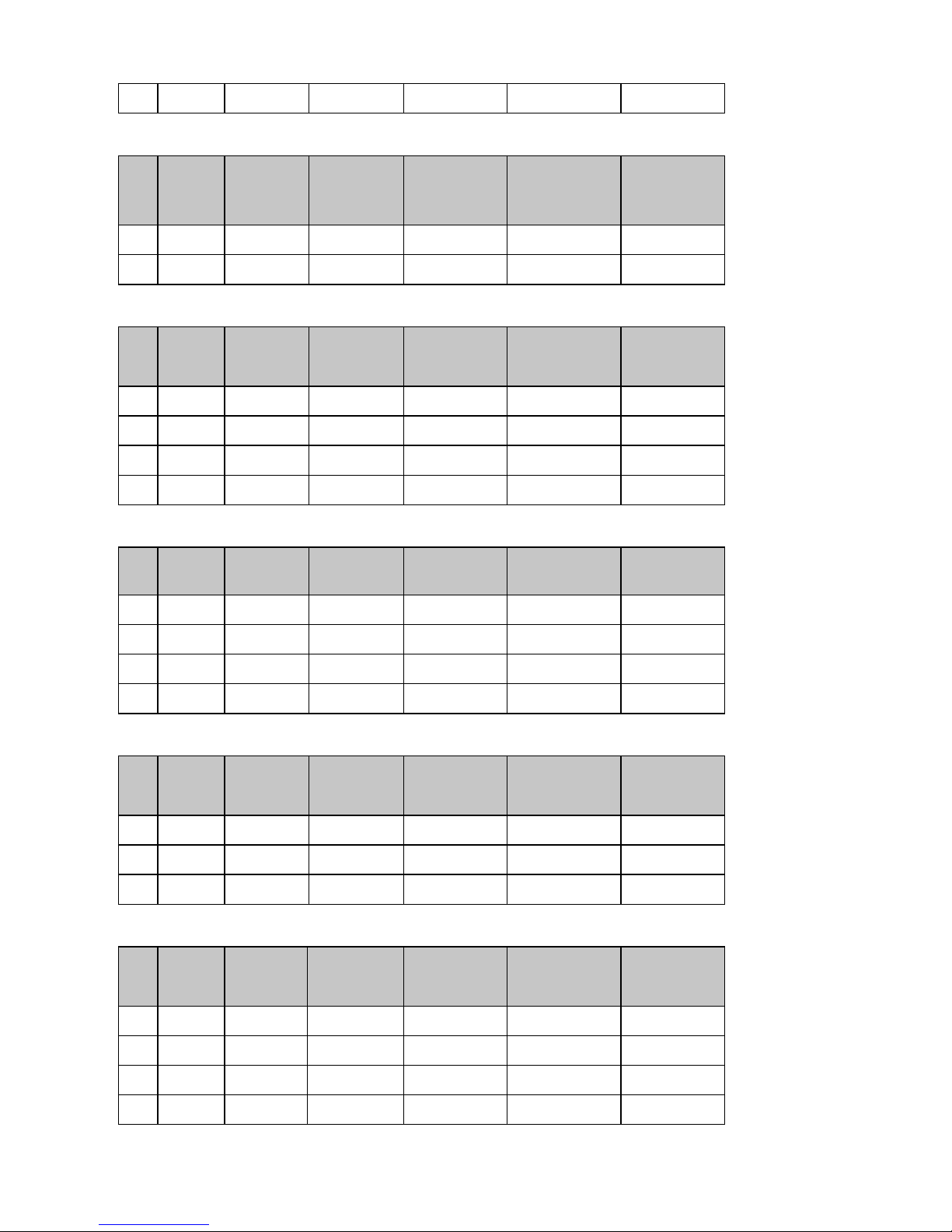
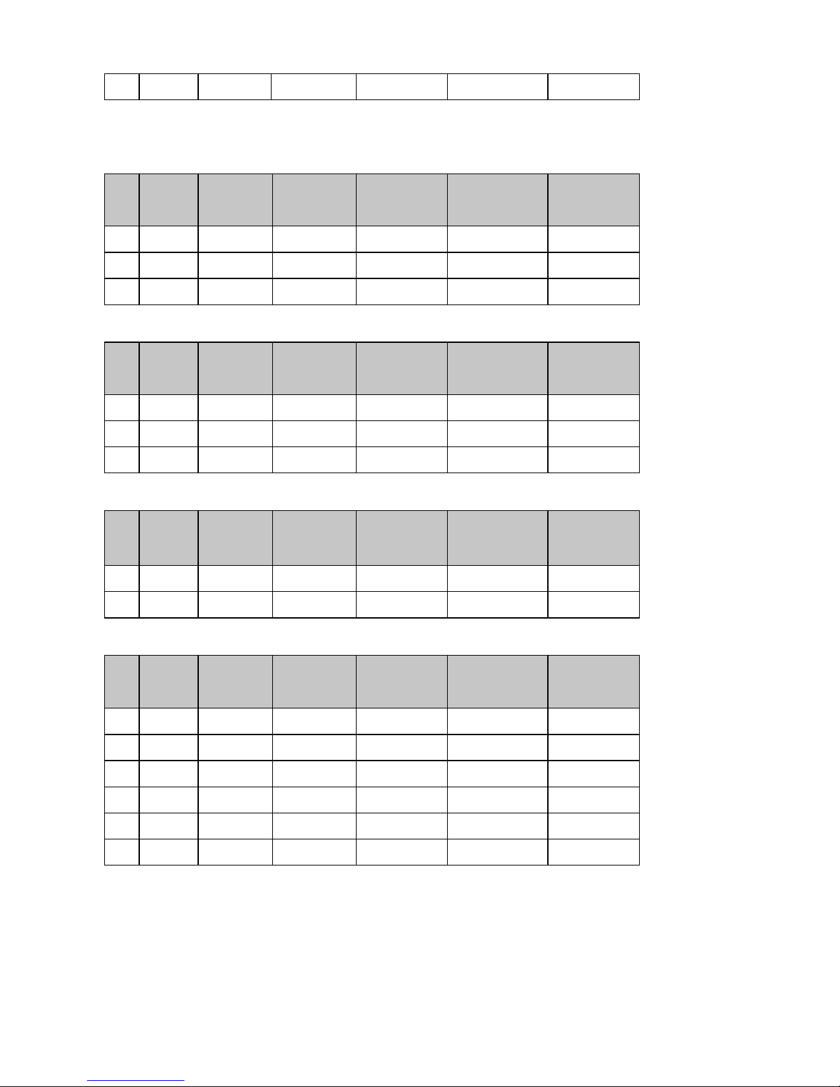
The existing adjustments:
Adjustment: Back bacon
Nr. Material State Multi-cutter
Bottom/mm
Multi-cutter
Top/mm
Length
mm
Pre-Comp
1 Pork cold 0°C 6 6 6,0 4
2 Pork cold 0°C 8 8 8,0 4
3 Pork froz.-2°C 6 6 6,0 4
4 Pork cold 2°C 6 6 6,0 2
5 Pork warm 30°C 6 6 6,0 0
Page 11

11
Adjustment: Streaky bacon
Nr. Material State Multi-cutter
Bottom/mm
Multi-cutter
Top/mm
Length
mm
Pre-Comp
1 Pork cold 0°C 6 6 6,0 4
2 Pork cold 0°C 8 8 8,0 4
3 Pork froz.-2°C 6 6 6,0 4
4 Pork cold 2°C 6 6 6,0 2
5 Pork warm 30°C 6 6 6,0 0
Adjustment : Bacon
Nr. Material State Multi-cutter
Bottom/mm
Multi-cutter
Top/mm
Length
mm
Pre-Comp
1 Pork cool 4°C 0 6 3,0 2
2 Pork cool 4°C 60 12 3,0 2
3 Pork cool 4°C 6 6 6,0 4
4 Pork cool 4°C 10 10 10,0 4
Adjustment: Meat cut into stripes
Nr. Material State Multi-cutter
Bottom/mm
Multi-cutter
Top/mm
Length
mm
Pre-Comp
1 Pork cold 0°C 60 12 6 4
2 Pork cool 4°C 60 12 8 4
3 Beef cold 0°C 60 12 8 6
4 Beef froz.-2°C 60 12 8 4
5Veal cold 0°C 60 12 10 4
6 Veal froz.-3° 60 12 12 4
7Turkey cold 0°C 60 12 10 2
8 Venison cool 4°C 60 12 10 4
Adjustment: Bierschinken
Nr. Material State Multi-cutter
Bottom/mm
Multi-cutter
Top/mm
Length
mm
Pre-Comp
1 Pork cool 4°C 24 24 24,0 4
2 Pork froz. - 3°C 24 24 20,0 2
3 Beef cold 0°C 24 24 20,0 4
4 Venison cold 0° C 24 24 18,0 2
Page 12
12
5 Pork cold 0°C 30 30 30,0 4
Adjustment: Inlay meat
Nr. Material State Multi-cutter
Bottom/mm
Multi-cutter
Top/mm
Length
mm
Pre-Comp
1 Pork cool 4°C 6 6 6,0 6
2 Pork cool 4°C 12 12 12,0 6
Adjustment: Goulash
Nr. Material State Multi-cutter
Bottom/mm
Multi-cutter
Top/mm
Length
mm
Pre-Comp
1 Pork cool 4°C 24 24 24,0 2
2 Beef cool 4°C 24 24 24,0 4
3 Pork cool 4°C 12 12 12,0 4
4 Beef cool 4°C 12 12 12,0 2
Adjustment: Meat salad with mayonnaise
Nr. Material State Multi-cutter
Bottom/mm
Multi-cutter
Top/mm
Lengthmm Pre-Comp
1 Pork cool 4°C 0 6 2,0 2
2 Pork cool 4°C 30 6 3,0 2
3 Pork cool 4°C 6 6 6,0 2
4 Pork cool 4°C 60 6 3,0 2
Adjustment: Meat salad
Nr. Material State Multi-cutter
Bottom/mm
Multi-cutter
Top/mm
Length
mm
Pre-Comp
1 Pork cool 4°C 0 6 2,0 2
2 Pork cool 4°C 30 6 3,0 2
3 Pork cool 4°C 60 6 3,0 2
Adjustment: Boiled ham
Nr. Material State Multi-cutter
Bottom/mm
Multi-cutter
Top/mm
Length
mm
Pre-Comp
1 Pork cool 4°C 24 24 2 2
2 Pork cool 4°C 12 12 2 2
3 Pork cool 4°C 10 6 6,0 2
4 Turkey cool 4°C 6 10 10 2
Page 13
13
5 Pork cool 4°C 60 6 6,0 2
Adjustment: Liver/Heart/Kidney
Nr. Material State Multi-cutter
Bottom/mm
Multi-cutter
Top/mm
Length
mm
Pre-Comp
1 Pork cool 4°C 24 6 3,0 6
2 Pork cool 4°C 12 12 12 4
3 Pork cool 4°C 24 24 4,0 2
Adjustment: Tribe/Lung
Nr. Material State Multi-cutter
Bottom/mm
Multi-cutter
Top/mm
Length
mm
Pre-Comp
1 Beef cool 4°C 30 30 10,0 6
2 Beef cool 4°C 60 60 3,0 2
3 Pork cool 4°C 60 6 3,0 6
Adjustment: Pork head
Nr. Material State Multi-cutter
Bottom/mm
Multi-cutter
Top/mm
Length
mm
Pre-Comp
1 Pork cool 4°C 12 12 12,0 2
2 Pork warm 30°C 12 6 6,0 0
Adjustment: Vegetables
Nr. Material State Multi-cutter
Bottom/mm
Multi-cutter
Top/mm
Length
mm
Pre-Comp
1Gherkin Raw 0 6 3,0 6
2 Carrots stewed 30 6 3,0 6
3Onions raw 6 6 6,0 6
4 Onions Raw 10 10 6,0 6
5 Carrots Stewed 30 15 3,0 4
6Onions raw 0 0 2,0 4
Page 14
14
Adjustment: Schnitzel (without sectioning blade, install bottom Multi-cutter.)
Nr. Material State Multi-cutter
Bottom/mm
Multi-cutter
Top/mm
Length
mm
Pre-Comp
1 Pork cool 4°C 10 0 10,0 0
2 Pork froz. -3°C 10 0 10,0 0
Adjustment : Roulades (without sectioning blade, install bottom Multi-cutter.)
Nr. Material State Multi-cutter
Bottom/mm
Multi-cutter
Top/mm
Length
mm
Pre-Comp
1 Pork cool 4°C 6 0 10,0 2
2 Beef cool 4°C 6 0 6,0 2
3 Veal cool 4°C 6 0 6,0 2
4 Turkey cool 4°C 6 0 6,0 2
Adjustment: Cordon Bleu (without sectioning blade, install bottom Multi-cutter.)
Nr. Material State Multi-cutter
Bottom/mm
Multi-cutter
Top/mm
Length
mm
Pre-Comp
1 Pork cool 4°C 10 0 10,0 6
2 Beef froz. -3°C 6 0 3,0 6
Adjustment: Steak (With sectioning blade and Multi-cutter frame.)
Nr. Material State Multi-cutter
Bottom/mm
Multi-cutter
Top/mm
Length
mm
Pre-Comp
1 Pork cool 4°C 0 0 10,0 0
2 Beef cool 4°C 0 0 10,0 0
Adjustment: Cutlets (with cutlet blade and Multi-cutter frame.)
Nr. Material State Multi-cutter
Bottom/mm
Multi-cutter
Top/mm
Length
mm
Pre-Comp
1 Pork cool 4°C 0 0 15,0 6
Adjustment : Salami
Nr. Material State Multi-cutter
Bottom/mm
Multi-cutter
Top/mm
Lengthmm Pre-Comp
1 Pork cool 4°C 12 12 4,0 6
2 Pork cool 4°C 24 24 4,0 6
Adjustment: Ochsenmaul
Nr. Material State Multi-cutter
Bottom/mm
Multi-cutter
Top/mm
Length Pre-Comp
Page 15

15
mm
1 Pork cool 4°C 0 0 2 0
2 Pork froz. -3°C 0 0 2 0
Adjustment: Cheese
Nr. Material State Multi-cutter
Bottom/mm
Multi-cutter
Top/mm
Length
mm
Pre-Comp
1hard soft 12 60 3,0 6
2hard soft 12 12 12 6
3soft hard 12 60 6,0 6
4soft hard 10 10 6,0 6
5 hard soft 6 60 3,0 4
Adjustment: Potatoes
Nr. Material State Multi-cutter
Bottom/mm
Multi-cutter
Top/mm
Length
mm
Pre-Comp
1 Carrots cool 4°C 12 12 10 6
Adjustment: Fondue Chinoise
Nr. Material State Multi-cutter
Bottom/mm
Multi-cutter
Top/mm
Length
mm
Pre-Comp
1 Beef froz. -3°C 0 0 1,0 0
2 Porc froz. -3°C 0 0 1,0 0
Page 16
16
3.4 The Multi-cutter
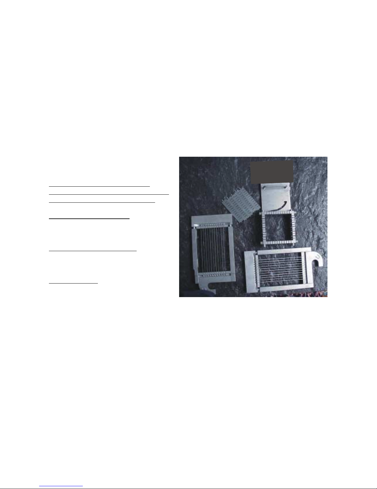
The Multi-cutter determines two out of the three dimensions of the cube or stripe.
The size of the cutting dimension is in mm, which means that the distance between two adjacent
knives is x mm.
The following cut-sizes are available for the High-Tech-Cutter:
5 mm x 5 mm, 6 mm x 6 mm, 8 mm x 8mm, 10 mm x 10 mm, 12 mm x 12 mm, 16 mm x 16 mm
20 mm x 20 mm, 24 mm x 24 mm, 30 mm x 30 mm, 32 mm x 32 mm, 40 mm x 40 mm,
60 mm x 60 mm.
Because the two dimensions are determined by the composition of two Multiplex-cutter-halves, it is
possible to achieve all sorts of combinations like 6 mm x 60 mm.
A Multi-cutter consists of:
A HighTech-cutter frame on which all
HighTech-cutter parts are mounted and the
frame itself is attached to the machine.
The Multiplex-cutter-half Top is marked with
O (Over) and, as the second cutting stage,
moves one plane of knives.
The Multiplex-cutter-half Bottom is marked
with U (Under) and, as the first cutting stage,
moves one plane of knives.
Product stabilizers which keep the product in
place while the knives are cutting
A Multi-cutter doesn’t always have to be composed of all the single parts. If, for example long
stripes are required, the Multiplex cutter Bottom is not needed and therefore the stabilizers are not
mounted either.
In case of a very hard product like smoked ham or cheese there is no need for the stabilizers as
well.
The two Multiplex-cutter-halves are in all cases mounted in such a way, that the Multiplex cutter half
bottom represents the bigger cut size and the Multiplex-cutter-half Top the smaller one.
Page 17
17
3.4.1 HighTech-cutter selection
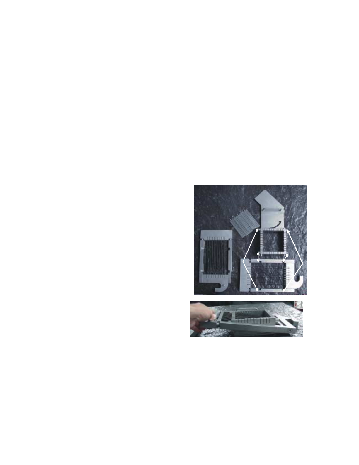
This operating manual contains the correct grid selection for SR 1 and SR 1 turbo.
For the selection of the HighTech-cutter frame the following applies: Always select the frame
with the smallest number of slits. This results in the best cut.
Of course it is possible to take a HighTech-cutter frame with lots of slits.
Because a soft product is processed in this example and a Multiplex-cutter-half bottom is used, it is
possible to use product stabilizers.
3.4.2 HighTech-cutter assembly
The operator assembling the Multi-cutter has to wear protective gloves against cuts and stabs.
A.At first all necessary Multi-cutter parts have to
be put on a table with a non slippery surface.
Only use as many product stabilizers as
determined by the Multiplex-cutter-half bottom.
Is there provision for only one knife, only put one
knife on the table, never more.
Check the knives for damage and bluntness
without touching them with the hands.
Only if all parts don‘t show any signs of wear and
tear it ist allowed to assemble the Multi-cutter.
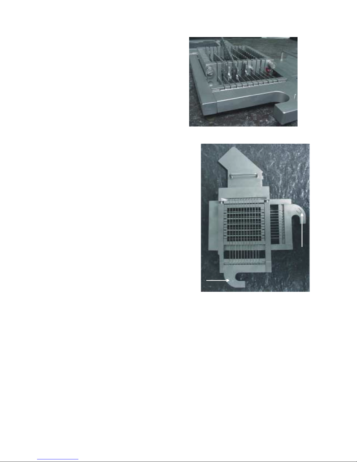
B.Put the bottom Multiplex cutter half with the
knife-edge facing down on to the bottom four
rollers of the Multi-cutter frame. Slide the Multiplex
-cutter half along the rollers until all four rollers
have engaged. The hook of the Multiplex
-cutter-half has to be on the right
hand side.
Page 18
18
C. Now the product stabilizer(s) have to be inserted
into the Multi-cutter frame from the side, on top of
the knives of the bottom Multiplex-cutter-half.
The stabilizers are inserted so far, that they are
not protruding on either side of the Multi-cutter
frame. In case of no Multiplex-cutter-half bottom,
no product stabilizer is inserted.
This applies also, when there is no stabilizer
support in the Multi-cutter frame.
D. Now the Multiplex-cutter-half top is put on to the top
four rollers of the Multi-cutter frame. Slide the
Multiplex-cutter-half along the rollers, until all four
rollers have engaged.
Take note that the Multiplex-cutter-half marked with
”U” lies behind the Multiplex-cutter-half marked
with ”O”.
To dismantle the Multi-cutter after a cutting process,
it is necessary to follow the steps described under
A – D in reverse order.
The handle on the Multi-cutter allows the operator to
lift it slowly with one hand in order to attach the
Multi-cutter to the machine.
!
!
Page 19
19
3.4.3 HighTech-cutter installation
Only install the Multi-cutter, which is nominated in the desired cutting program. The operator has to
wear protective gloves against cuts and stabs while working in the cutting area.
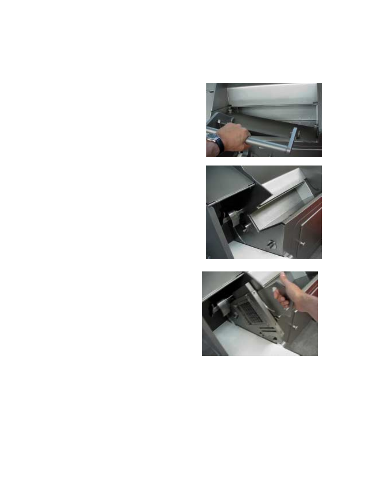
A. Open the processing shaft and remove
the shaft slider by sliding it diagonally
out of the guides on the side.
B. Turn the blade away from the cutting area,
so that the tip of the blade points to the floor.
C. Before sliding the Multi-cutter into the Multi-
cutter fastener, it has to be inserted into the sector
of the sheet metal as high up as possible.
Now the Multi-cutter can be inserted into the
fastener.
D. Turn the blade on the knife shaft twice by 360°.
If this can be done without any problems, the
process shaft and the cutting area door can be
closed again.
If it is not possible to turn the blade two
revolutions or to lock the shaft, it has to be
checked if the drive bolts have engaged properly in the drive hooks of the Multiplex-
cutter half.
After checking and rectifying the problem, the
blade again has to be turned twice by 360°.
Page 20
20
3.4.4 HighTech-cutter maintenance
In the end a cutting machine always depends on sharp knives, because they keep the wear and
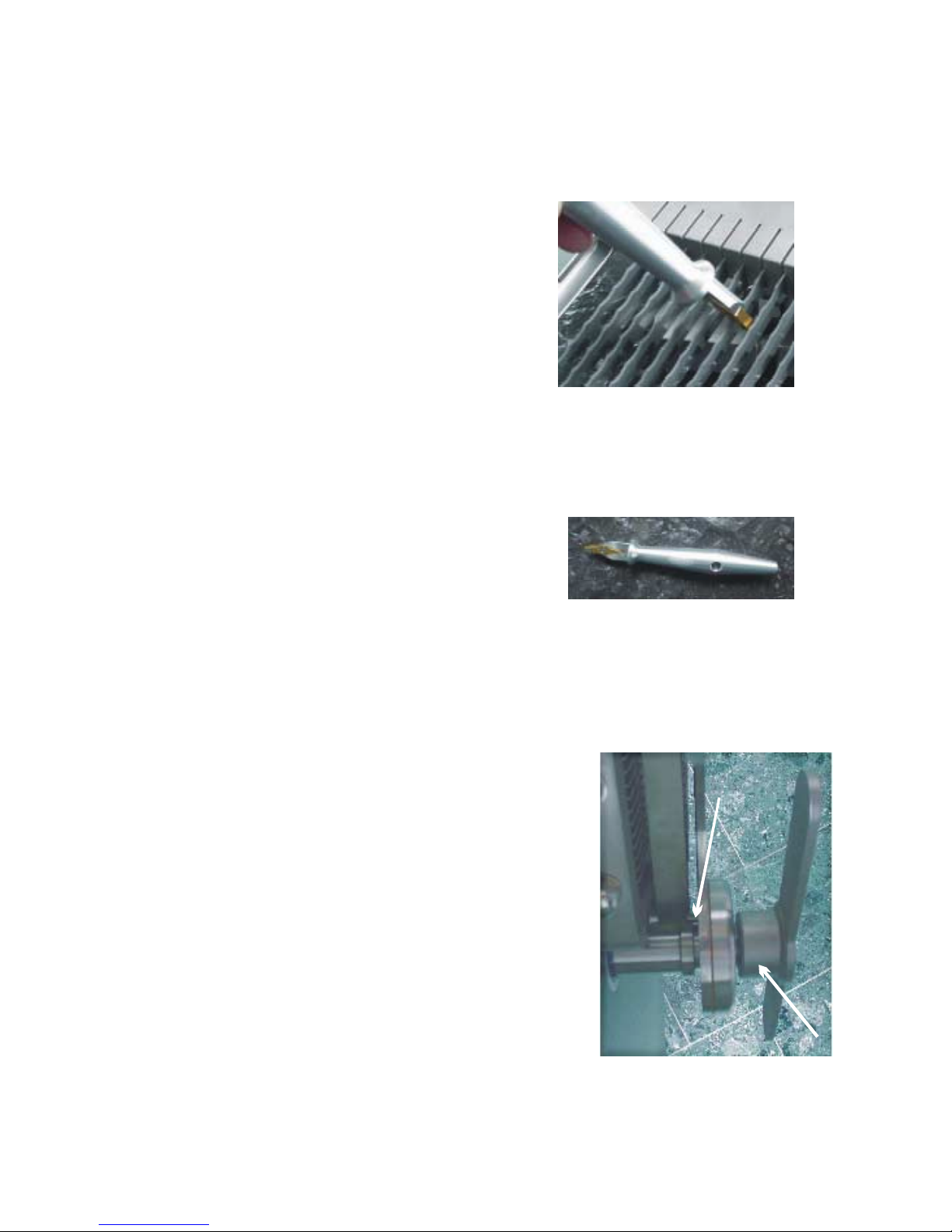
tear to a minimum and create a beautiful cut. For this reason, the Multiplex cutter halves and the
knives should be sharpened with a suitible tool every 50
operating hours. Please use special protective gloves
against cuts and stabs for this process!
Preferably use Rühle’s knife sharpener and it will only take
2 minutes to resharpen a complete Multiplex-cutter half.
For this purpose, the Multiplex-cutter half is positioned on a
non slippery table in such a way, that the knife edges face
the operator. First slide the knife sharpener along one side
of the knife and then on the opposite side.
Never exert too much pressure – this could result in an even blunter knife. Again use special
protective gloves against cuts and stabs.
The Rühle knife sharpener is well balanced and has as
one of its components Vidia steel. The construction of
the sharpener allows you to work even under very
cramped conditions without any problems. There is a
special hanger provided in the tool box to store the Rühle
knife sharpener.
3.5 The sectioning blade
All the time, when handling the sectioning blade, protective
gloves against cuts and stabs have to be worn.
For the sectioning blade too, the principle of the sharp
knife and the beautiful cut applies.
To install the sectiopning blade it has to be put on the
blade shaft in the cutting area first.
Now turn the sectioning blade around the stationary blade
shaft until it engages and can only be turned together with
the blade shaft.
Hold the sectioning blade in this position and at the same time
screw the wing nut counterclockwise onto the blade shaft, until
it touches the blade.
Page 21
21
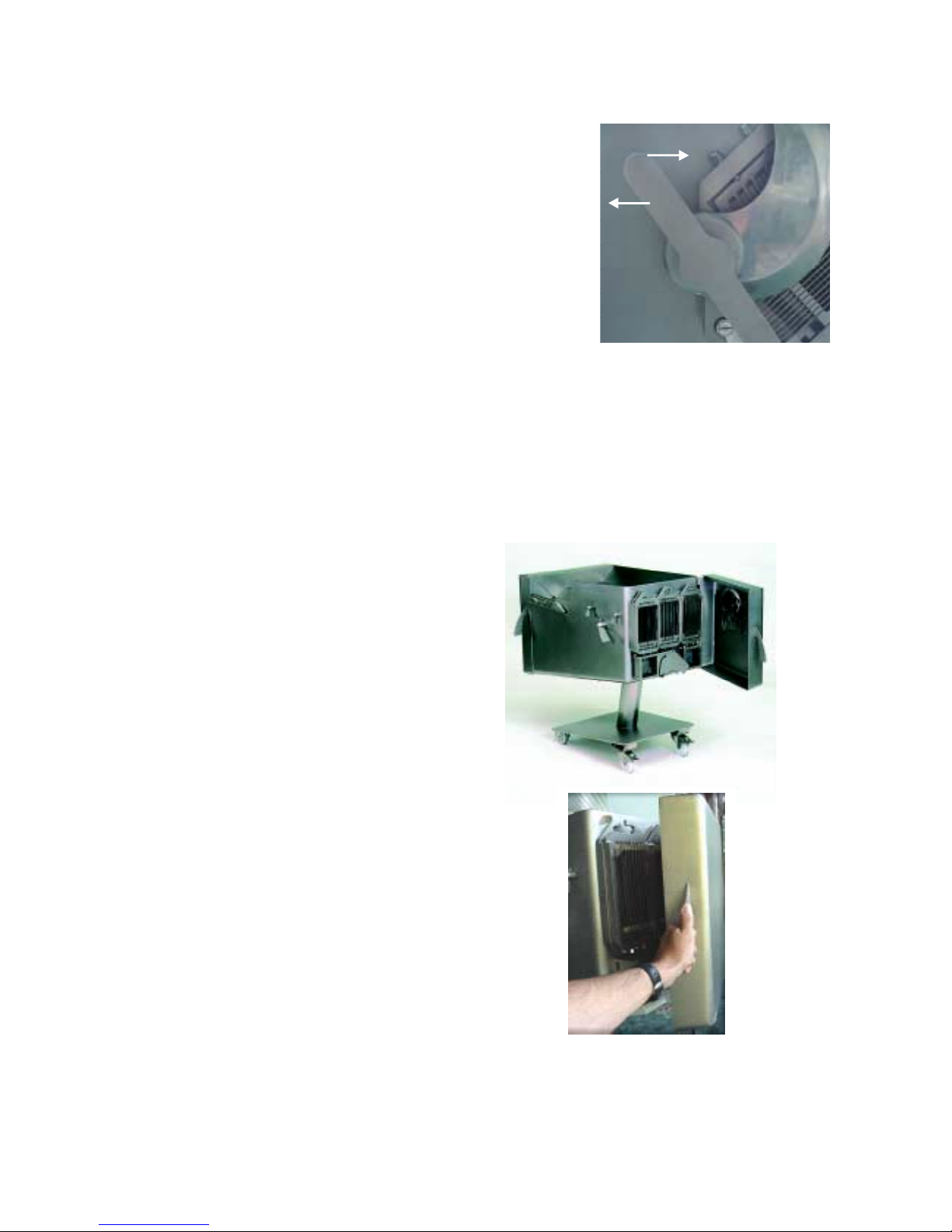
The wing nut is fastened counterclockwise and loosened clockwise
so that the sectioning blade doesn’t turn loose during the cutting
process.
Now loosen the wing nut by a full turn and fasten the nut again
by swinging it round with lots of speed. This is sufficient to hold
the blade in position.
The plunger plate can be used to loosen the wing nut by giving the wing nut a slight push with
the plate in a clockwise direction.
3.6. The tool box
The storage area can hold 2 Multi-cutter frames, 6 MultiplexCutter-halves, 5 stabilizers and 1 knife sharpener – this means good order,
safety and hygiene for all the accessories and the operator.
Should the machine be equipped with special plunger plates, then these
Items can be stored under the tool box.
The tool box is located directly at the rear side
of the machine.
After unlocking the hood of the tool box, it
can be moved up to 180° to the right hand
side by lifting it slightly.
A door latch keeps the door closed, so that
it can be opened with a soft pull and closed with
a soft push.
Only put clean, disinfected and dry accessories
into the tool box.
Apart from the accessories belonging to the
machine, no other parts are allowed to be stored
inside the tool box.
Open
Closed
Page 22
22
3.7 Feeding the machine
The feed hight is 1.100 mm above floor level. During manual feed no more than
50 kg of produkt should be put on to the machine.
for a comfortable operation a maximum of 25 kg is recommended.
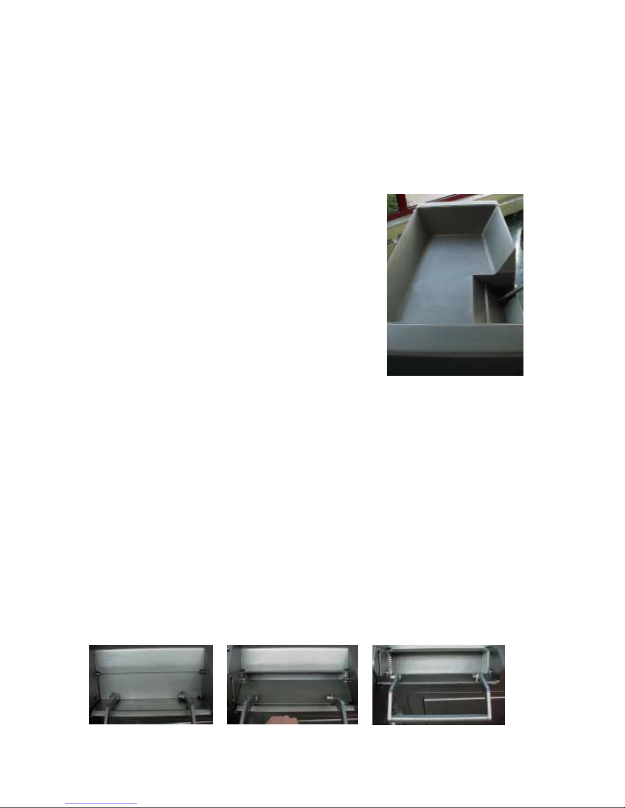
3.7 .1The work bench
When the machine is positioned correctly the
work bench has a slope of 3° towards the
back of the machine.
This guarantees that the product slides safely into
the process chamber and liquid will run off
through the processing chamber after cleaning.
All sorts of preparations can be carried out on
the work bench, from arranging to cutting.
3.7.2 The shaft – charging
The filling of the shaft is decisive for the cut appearance.
that’s why special care has to be taken when filling the
shaft.
Following rules should be observed in order to achieve the best results:
....put as much product as possible into the shaft
....never use very hard and very soft product at the same time
....put fat, tendons and vleece towards the top
Only use products which are approved and mentioned by name in the processing programs of the
operating terminal.
If other products are intended to be used then written approval of Rühle is required.
Page 23
23
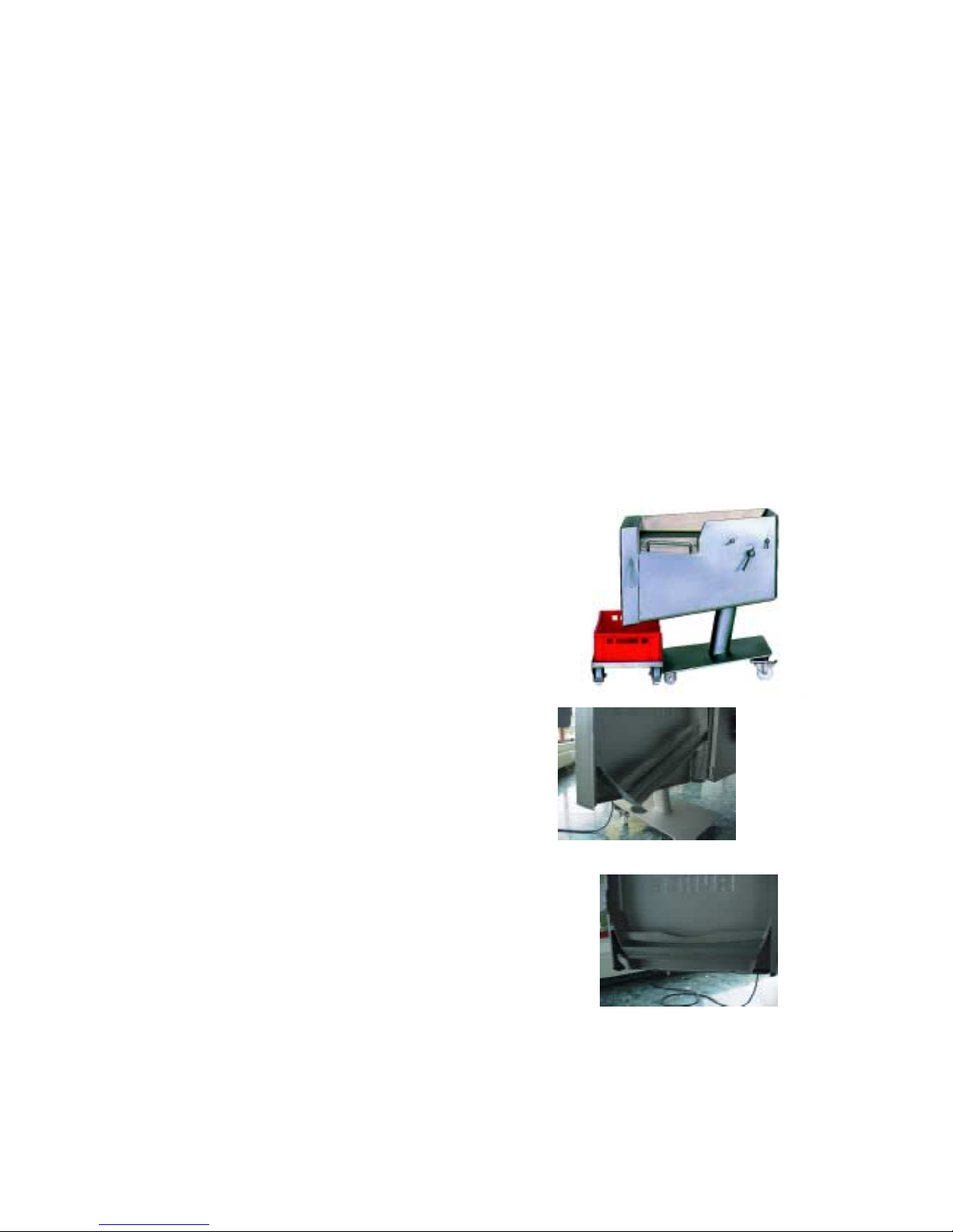
To open the shaft push the handle about 1 cm away from you to release the locking mechanism.
then pull the handle towards you until the limit stop is reached. Now let go off the handle so that
the slider can lock itself in this position through its own weight. After filling, ideally with 110% of the
shaft volume, locking and pre-compacting is started. Always keep both hands on the handle until
the shaft is locked. Lift the handle a few millimeters out of its locked position and then push the
slider down until the shaft is completely closed. This process is finished when the bottom part of the
slider lies against the machine and when the machine starts working automatically with a started
process program.
3.8. Product discharge
The product discharge for SR 1 and SR 1 turbo is always composed of cutting area door and
discharge funnel.
3.8.1 The use of boxes
The machine has a discharge height of 450 mm.
this makes it possible to use boxes of up to
300 mm height on top of a trolley.
Therefore there is the choice to use euro standard
boxes of the sizes E 1, E 2 and E 3 respectively.
The discharge funnel inside the cutting area door
Avoids Product from falling passed the boxes.
The funnel is inserted by holding it at an angle
followed by lowering it in a horizontal position
on to the holders at the bottom of the cutting
area door.
Page 24

24
4. Cleaning instruction
The High-Tech-Cutter SR1 and SR1 turbo is constructed in such a way, that all parts getting into
contact with the product can be reached from the operating side and from the front of the machine.
Correct cleaning of the machine is a condition for good food and prolongs the life of the machine.
That’s why the cleaning instruction has to be read, understood and adhered to by the person
responsible for the cleaning of the machine
4.1 Safety hints
- The cleaning instruction has to be read before cleaning is started. The supervisor has to make
sure, that the cleaning instruction has been read and understood by the cleaning personal.
- The cleaning personal has to clean the machine as directed and follow the instruction to the
point. The supervisor has to write an instruction for the cleaning procedure.
- The cleaning personal has to tell the supervisor about defects of the machine immediately.
- The cleaning personal has to use the recommended cleaning agents and disinfectants.
- Don’t make any alterations to the machine.
- The cleaning agents and disinfectants have to be made up to solutions according to the
manufacturers product data sheet. Protective gear has to be worn.
- Preparing the machine for cleaning is part of the machine operation. That’s the reason,
why only a person, who has read and understood the operating manual, should undertake
the cleaning preparation.
4.2. Cleaning agents and disinfectants
The following cleaning agents and disinfectants have to be used:
A. Cleaning agent: Alkaline cleaning: P3-topax 19, P3-topax 66
Acidal cleaning: P3-topax56
Disinfectant: P3-topax 99, P3-topax 66
Source of supply: Henkel Hygiene GmbH, Reisholzer Werftstraße 38 - 42
D - 40589 Düsseldorf, Tel.: 0211 / 9893-706
B. Cleaning agent: Alkaline cleaning: SOMPLEX Fettlöser
Acidal cleaning: Somplex Schaum Sauer
Disinfectant: P3-topax, P3-topax 91
Source of supply: Diverseylever, Morschheimer Straße 5, D-67292 Kirchheimbolanden
Page 25

25
4.3 Cleaning procedure
Before cleaning the machine, the operator has to prepare the machine for the cleaning process and
follow the sequence below exactly.
a. Start machine and stop after 2 seconds.
b. Remove all objects lying on top of the machine. Open tool box.
c. Remove box from underneath produkt discharge.
d. Open cutting area door completly and remove discharge funnel.
e. Remove fastening slider from the processing shaft.
f. Remove the sectioning blade.
g. Place cutting blade in a safe storage area.
h. Remove the Multi-cutter and dismantle it.
i. Put the main switch of the machine to ”0”.
k. Remove plunger plate by sliding it out of the processing shaft towards the top.
l. Use drinking water from a water hose or a pressure cleaner to hose down the machine and the
dismantled attachments, which have to be in a secured position, in the temperature range from
50 – 60 °C (according to the softening point of fat).
m. Put the cleaning agent solution into a pressure foam generator at 3 bar, hose the foam onto
the machine and the attachments and wait for 15 minutes.
n. Use drinking water from a water hose or a pressure cleaner to hose down the machine and
the dismantled attachments in the temperature range from 50 – 60 °C followed by drying
with compressed air which is suitable for food (according to DIN ISO 85731-1).
o. Remove the processing shaft and the fastening slider from the machine
p. Remove the plunger plate by sliding it out of the processing shaft towards the
top.
q. Pull the pre-compacting plunger away from the machine and dismantle the
attachments.
A
B
C
Page 26

26
r. Untertake a visual check for cleanlyness of the machine and the attachments and repeat the
the cleaning steps ”L to N ” if required.
s. Fill the disinfectant solution into a pressure cleaner with a power rating of at least 3 bar,
spray the solution onto the machine and the attachments and wait for 20 minutes.
t. Use drinking water from a water hose or a pressure cleaner to hose down the machine and the
dismantled attachments in the temperature range from 50 – 60 °C, followed by drying
with compressed air, which is suitable for food (according to DIN ISO 85731-1).
u. Assemble the machine following the sequence ”K --> A”.
5. Technical service
All works which have to do with the technical service are only allowed to be carried out by
Rühle technicians and by persons with a written approval from Rühle. A difference is made
between regular maintenance and regular service, so that the approval has to be valid for the
respective service.
5.1 Regular maintenance
Regular maintenance has to be carried out at least once a week. This allows little errors or
wear and tear to be detected before a major damage occurs.
Not performing regular maintenance leads to technical consequences and a loss in quality of the
product. Irregularities discovered during regular maintenance have to be rectified immediately.
Apart from the machine system which is covered by the Rühle guarantee, there are parts which
are not wear resistant and are parts which are not wear resistant and are there fore not covered
by guarantee. With the High-Tech-Cutters SR1 and SR1 turbo grid knives, cutting blade and grid
drive bolts are such parts.
Maintenance plan
a. Dismantle machine according to the cleaning instruction and check for ease of operation,
abrasion of material and any traces of wear and tear.
b. Sharpen the sectioning blade with the sharpener and inspect the blade for
damage.
c. Sharpen the blade of the processing shaft – sliding fastener on the top side and inspect for
damage.
Inspect the sliding surface of the sliding fastener.
d. Sharpen the Multi-cutter knives of all Multiplex-cutter-halves with the sharpener and inspect for
damage.
Page 27

27
e. Check Multi-cutter – drive bolt for ease of operation and the end clearance and make sure, that
the running surfaces of the bearings show no sign of having plane surfaces.
f. Check the cam rollers of all Multi-cutter frames for ease of operation and make sure, that the
running surfaces of the bearings show no sign of having plane surfaces.
g. Check all safety limit switches and safety covers according to the safety instruction.
h. Undertake a visual check of the complete machine body. Obvious changes to the surface
have to be rectified immediately.
5.2 Regular service
Regular service on the machine has to be performed every 2000 operating hours or at least
once a year, in case that the machine has not been running for 2000 hours.
The regular service consists of the following steps:
a. Exchange of the Multi-cutter drive bolts
b. Exchange of the LC unit with battery set of the fully automatic grease dispensers.
c. Smoothing and readjusting the sectioning blade.
d. All the maintenance work according to ”Regular maintenance”
e. Check the main clutch and the free wheel bearings.
f. Check the overload clutch of the pre-compacting plunger.
g. Check the linear drive for the forward feed adjustment.
h. Check the safety functions.
i. Use operating panel to read error protocol and examine the errors.
K. Perform a test run with the machine open, using the Bierschinken program.
Page 28

28
5.3 Errors
Error Solutions
Bad cross section of cut Check product for required temperature
Correct process machine adjustment?
Correct grid mounted?
Sectioning blade blunt or damaged?
Grid knives blunt or damaged?
No stabilisers mounted on grid?
Product falling past the collecting
vessel.
Machine is not level (spirit level)?
Collecting vessel not positioned correctly?
Liquid splashes on to the
operator
Product behind the plunger?
Product to hot?
Pre-compacting set too high?
Can`t close tool box. Cutting blade inserted wrongly?
Grid halves put together incorrectly?
Feeding system doesn‘t operate Operating terminal is not switched on?
„Emergency Stop“ because not all safety switches are
connected?
Machine doesn’t react Shaft is not closed?
No grid installed in cutting area?
Cutting area door not closed?
Machine performance not
sufficient
Selection of the correct machine adjustment?
Process shaft filled sufficiently?
Grid can’t be removed from
cutting area
Fastening slider not removed?
Sectioning blade not facing towards the bottom?
Should an error occur, which is not mentioned here, or should it not be possible, to rectify the
problem with the solutions mentioned above, then Rühle will help – just call:
+49 7748 - 523-0.
Page 29

29
6. Technical documentation
Technical data
Current: Three-phase current
Voltage: 400 V AC
Control voltage: 24 V DC
Current: 16 A
Power input: 1,5 kW
Should these data not confirm with the data on the data
plate, then the values of the data plate apply. For safety
reasons check the data with the manufacturer and get
written confirmation.
The data plate is positioned under the main switch on
the back side of the machine.
Compressed air suitable for food according to DIN ISO 8573-1
Oil: Class 1 / Particle: Classe 1 / Water: Classe 4
Power plug: CEE-Plug 16 A , 5 - poles
Working place noise level under 65 dBa
6.1 Circuit diagrams
The circuit diagrams of your High-Tech-Cutter SR 1 and SR1 turbo are supplied together with the
machine. These diagrams are kept inside the switch box, in order to have them handy for the
service technician. In case of reselling the machine, the circuit diagrams have to be handed over as
well.
6.2 List of spare parts
The High-Tech-Cutter SR1 and SR1 turbo is only allowed to be serviced by Rühle service technicians
and by authorised persons. These persons have all the necessary information and a list of spare
parts for the machine.
Damage to parts is usually not caused by the part itself – that’s why a fault diagnosis has to be
carried out. For this reason, there is no list of spare parts included, because non-qualified repairs can
do more harm than good..
In case of damage to the machine or a spare part, write down the machine type and machine
number, call +49 7748 – 523-0 and we will help you find the fault and send you the right spare
parts.
Typ
Anschlußwert
Nr. Baujahr
CE
SR 1 (turbo)
2001 9999
400 V/50 Hz/16 A/3/1,5 kw
Page 30

30
7. Index
Adjustments p. 12 Faults p. 33 Phone-service p. 1, 34, 35
Assembly p. 30 General view of machine p. 6 Safety hints p. 3, 28
CE-conformity decl. p. 4 Knife sharpening p. 22 Service interval p. 32
Compressed air p. 34 Machine feet p. 7 Service p. 1, 34, 35
Conformity decl. p. 5 Multicutter p. 18 Sharpening p. 22
Data plate p. 34 Multiplex-cutter half p. 18 Spare parts p. 35
Disinfecting p. 29 Noise level p. 34 Stabilisers p. 18
Dismantling p. 29 Plug p. 34 Switch p. 8
Door-lock p. 24 Plunger p. 25 Technical data p. 34
Errors p. 33 Power supply p. 8, 34 Tool box p. 23
 Loading...