

RuggON VX-601 User Manual

VX-601
User’s Manual

VX-601
V1.2
2

VX-601
V1.2
3
Contents
CONTENTS ..................................................................................................................................................................... 3
SAFETY PRECAUTIONS ........................................................................................................................................... 6
REGULATORY AND CERTIFICATION .................................................................................................................. 8
FCC ................................................................................................................................................................................................... 8
CE MARKING .................................................................................................................................................................................. 9
RED .................................................................................................................................................................................................. 9
LITHIUM BATTERY SAFETY STATEMENT ............................................................................................................................... 9
CHAPTER 1. PRODUCT INTRODUCTION ........................................................................................................ 10
HARDWARE SPECIFICATIONS ................................................................................................................................................ 10
OPERATING SYSTEM SUPPORT ........................................................................................................................................... 11
ENVIRONMENT ............................................................................................................................................................................ 11
I/O PORTS .................................................................................................................................................................................... 12
DIMENSION AND WEIGHT ........................................................................................................................................................ 13
VX-601 Standard ........................................................................................................................................................................ 13
VX-601 with I/O water-proof box ....................................................................................................................................... 14
PACKAGE LIST ............................................................................................................................................................................ 15
CHAPTER 2. HARDWARE INSTALLATION ...................................................................................................... 16
M.2 MODULE ............................................................................................................................................................................... 16
Installing/Removing a M.2 Module ................................................................................................................................... 16
INSTALLING/REMOVING THE SIM CARD ............................................................................................................................ 18
Internal SIM slot ........................................................................................................................................................................... 18
INSTALLING/REMOVING THE WWAN MODULE ............................................................................................................... 19
INSTALLING WWAN ANTENNAS ........................................................................................................................................... 20
External Antennas ...................................................................................................................................................................... 20
CHAPTER 3. HARDWARE MOUNTING ............................................................................................................. 21
CHAPTER 4. START UP .......................................................................................................................................... 22
POWERING THE SYSTEM ........................................................................................................................................................ 22
Connector Power ........................................................................................................................................................................ 22
Power source from car power cable ..................................................................................................................................... 23

VX-601
V1.2
4
Power source from external power adapter ..................................................................................................................... 23
Power on the System ............................................................................................................................................................... 24
LED STATUS................................................................................................................................................................................ 25
ADJUST THE SPEAKER VOLUME .......................................................................................................................................... 26
AUTO-BRIGHTNESS ADJUSTMENT ...................................................................................................................................... 26
MANUAL BRIGHTNESS ADJUSTMENT ................................................................................................................................. 27
INTERNAL MICROPHONE ......................................................................................................................................................... 27
DISPLAY ON/OFF ........................................................................................................................................................................ 27
DEFROST ON/OFF (ONLY AVAILABLE UPON REQUEST) ................................................................................................. 27
PROGRAMMABLE BUTTONS ................................................................................................................................................... 28
POWER MANAGEMENT ............................................................................................................................................................ 28
CHAPTER 5. JUMPERS AND CONNECTORS ................................................................................................ 29
BOTTOM VIEW ............................................................................................................................................................................... 29
EXTERNAL CONNECTORS PIN ASSIGNMENTS ................................................................................................................ 30
Power Connector ........................................................................................................................................................................ 30
RS-232/422/485 Port (COM1) ............................................................................................................................................ 30
RS-232 Port (COM2) ................................................................................................................................................................ 31
GPIO, CANbus and DR Port ............................................................................................................................................... 32
CHAPTER 6. DASHON SETTING ......................................................................................................................... 33
DEVICE INFORMATION .............................................................................................................................................................. 34
VEHICLE STATUS ....................................................................................................................................................................... 35
COMMUNICATION SETTING .................................................................................................................................................... 36
Enable/ Disable Module .......................................................................................................................................................... 36
WWAN Communication Setting ......................................................................................................................................... 37
SYSTEM STATUS & SETTING ................................................................................................................................................. 38
Power Management Setup ................................................................................................................................................... 38
Wake up Setting .......................................................................................................................................................................... 44
I/O Configuration ......................................................................................................................................................................... 47
Brightness Setting ...................................................................................................................................................................... 48
Watchdog Timer .......................................................................................................................................................................... 49
Programmable Button .............................................................................................................................................................. 51
LOCATION AND SENSOR .......................................................................................................................................................... 54
Enable/ Disable GPS Receiver .......................................................................................................................................... 56
Serial Port Setting ...................................................................................................................................................................... 57

VX-601
V1.2
5
Baud Rate Setting ...................................................................................................................................................................... 57
CHAPTER 7. MAIN BIOS SETTING ..................................................................................................................... 58
SET BOOT SEQUENCE ............................................................................................................................................................. 58
SET THE SYSTEM CONFIGURATION ..................................................................................................................................... 59
Setting the System Date ........................................................................................................................................................ 59
Setting the System Time ........................................................................................................................................................ 59
SYSTEM INFORMATION ............................................................................................................................................................ 60
BOOT FEATURES ....................................................................................................................................................................... 60
MISCELLANEOUS CONFIGURATION ..................................................................................................................................... 61
ACCOUNT’S PASSWORD SETTING ....................................................................................................................................... 61
HDD SECURITY SETTING ....................................................................................................................................................... 62
CHAPTER 7. SETUP WI-FI HOTSPOT ............................................................................................................... 63

VX-601
V1.2
6
Safety Precautions
1. Read these safety instructions carefully.
2. Keep this user’s manual for later reference.
3. Disconnect this equipment from any AC outlet before cleaning. Use a damp cloth. Do
not use liquid or spray detergents for cleaning.
4. For plug-in equipment, the power outlet socket must be located near the equipment and
must be easily accessible.
5. Keep this equipment away from humidity.
6. Put this equipment on a stable surface during installation. Dropping it or letting it fall
may cause damage.
7. Do not leave this equipment in either an unconditioned environment or in an above
40oC storage temperature as this may damage the equipment.
8. The openings on the enclosure are for air convection to protect the equipment from
overheating. DO NOT COVER THE OPENINGS.
9. Make sure the voltage of the power source is correct before connecting the equipment
to the power outlet.
10. Place the power cord in a way so that people will not step on it. Do not place anything
on top of the power cord. Use a power cord that has been approved for use with the
product and that it matches the voltage and current marked on the product’s electrical
range label. The voltage and current rating of the cord must be greater than the voltage and current rating marked on the product.
11. All cautions and warnings on the equipment should be noted.
12. If the equipment is not used for a long time, disconnect it from the power source to avoid
damage by transient overvoltage.
13. Never pour any liquid into an opening. This may cause fire or electrical shock.
14. Never open the equipment. For safety reasons, the equipment should be opened only
by qualified service personnel.
15. If one of the following situations arises, get the equipment checked by service
personnel:
a. The power cord or plug is damaged.
b. Liquid has penetrated into the equipment.
c. The equipment has been exposed to moisture.

VX-601
V1.2
7
d. The equipment does not work well, or you cannot get it to work according to the
user’s manual.
e. The equipment has been dropped and damaged.
f. The equipment has obvious signs of breakage.
16. Do not place heavy objects on the equipment.
17. The unit uses a three-wire ground cable which is equipped with a third pin to ground the
unit and prevent electric shock. Do not defeat the purpose of this pin. If your outlet does
not support this kind of plug, contact your electrician to replace your obsolete outlet.
18. CAUTION: DANGER OF EXPLOSION IF BATTERY IS INCORRECTLY RE- PLACED.
REPLACE ONLY WITH THE SAME OR EQUIVALENT TYPE RECOMMENDED BY
THE MANUFACTURER. DISCARD USED BATTERIES ACCORDING TO THE
MANUFACTURER’S INSTRUCTIONS.

VX-601
V1.2
8
Regulatory and Certification
FCC
This device complies with Part 15 of the FCC Rules. Operation is subject to the following two
conditions:
1. This device may not cause harmful interference.
2. This device must accept any interference received, including interference that may
cause undesired operation.
This equipment has been tested and found to comply with the limits for a Class B digital
device, pursuant to Part 15 of the FCC Rules. These limits are designed to provide
reasonable protection against harmful interference in a residential installation. This
equipment generates, uses, and can radiate radio frequency energy and, if not installed and
used in accordance with the instructions, may cause harmful interference to radio
communications. However, there is no guarantee that interference will not occur in a
particular installation. If this equipment does cause harmful interference to radio or television
reception, which can be determined by turning the equipment off and on, the user is
encouraged to try to correct the interference by one or more of the following measures:
Reorient or relocate the receiving antenna.
Increase the separation between the equipment and the receiver.
Connect the equipment into an outlet on a circuit different from that to which the
receiver is connected.
Consult the dealer or an experienced radio/TV technician for help.
Shielded interconnect cables and shielded AC power cable must be employed with this
equipment to insure compliance with the pertinent RF emission limits governing this device.
Changes or modifications not expressly approved by the system’s manufacturer could void
the user’s authority to operate the equipment.
Any changes or modifications not expressly approved by the party responsible
for compliance could void the user’s authority to operate the equipment.
This device is operation in 5.15 – 5.25GHz frequency range, then restricted in
indoor use only, Outdoor operations in the 5.15 – 5.25GHz is prohibit.

VX-601
V1.2
9
.
CE Marking
This product has passed the CE test for environmental specifications when shielded cables
are used for external wiring. We recommend the use of shielded cables. Please contact your
local representative for ordering information.
This product has passed the CE test for environmental specifications. Test conditions for
passing included the equipment being operated within an industrial enclosure. In order to
protect the product from being damaged by ESD (Electrostatic Discharge) and EMI leakage,
we strongly recommend the use of CE-compliant industrial enclosure products.
RED
This device complies with the essential requirements of the R&TTE Directive 1999/5/EC.
Lithium Battery Safety Statement
Lithium battery inside. Danger of explosion if battery is incorrectly replaced. Replace only
with same or equivalent type recommended by battery manufacturer.
THIS PRODUCT CONTAINS LITHIUM-ION BATTERY PACKS. IT MUST BE
DISPOSED OF PROPERLY. CONTACT LOCAL ENVIRONMENTAL
AGENCIES FOR INFORMATION ON RECYCLING AND DISPOSAL PLANS IN
YOUR AREA.
VX-601
V1.2
10
Chapter 1. Product Introduction
VX-601 is the 12.4” in-vehicle terminal with 700/1200nits brightness display and is designed
for flexible wireless connection capability expansions. The device is built for warehouse
management, harbor management, asset management applications. VX-601’s optimized
power system design for cold cranking, load dump, transient voltage and ESD. With IP66
protection rating, wide temperature design, wide power range input, and rich expanding
interfaces supporting in-vehicle connectivity.
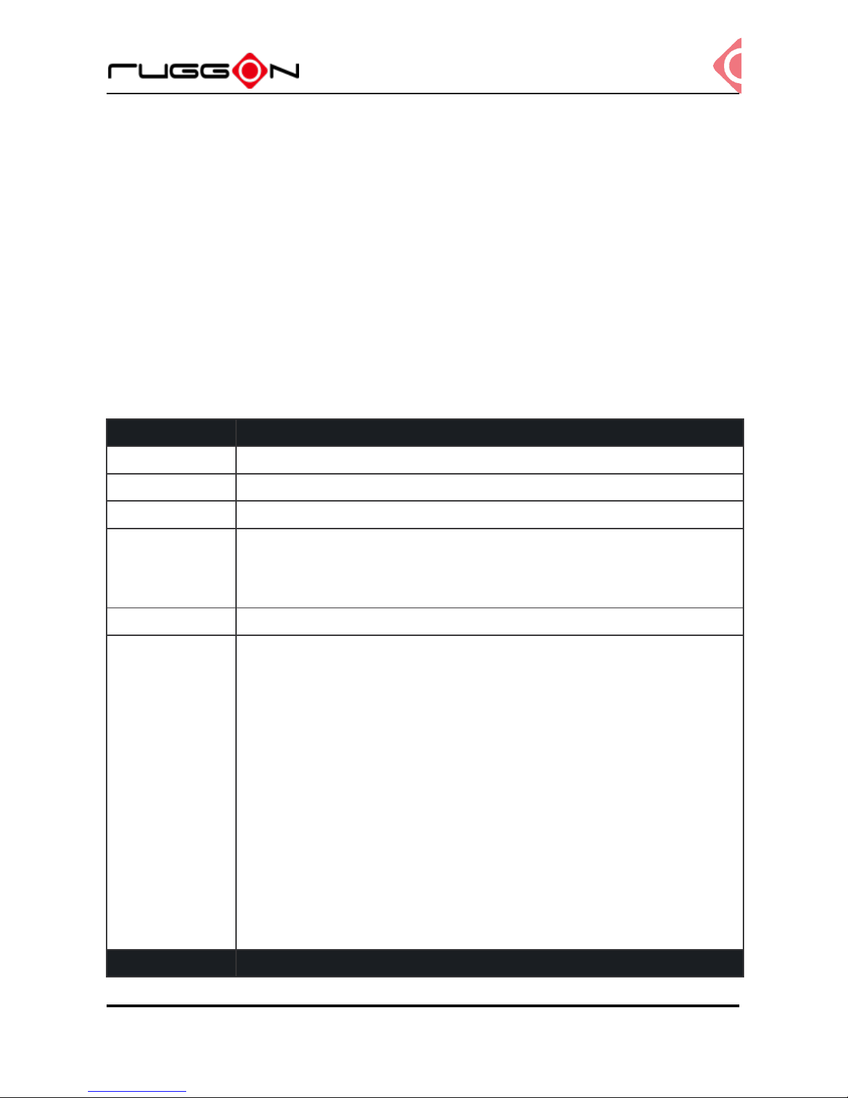
Hardware Specifications
Item
Description
Processor
Intel® Core™ i5-6300U 2.4GHz Processor
Memory
DDR3L 4GB SDRAM up to 32GB (by request)
Storage
M.2 2280 x 1, Micro SD slot x 1
Display
12.1-inch XGA (1024 x 768)
700/ 1200 nits
Viewing angel: 160(H)/ 160(V) (CR>10)
Touch Panel
Projected Capacitive Touch Screen
Wireless
Connectivity
802.11 ac/a/b/g/n 2x2
Bluetooth 4.0 + HS
GPS / QZSS or GLONASS (COM3)
1 mini PCIe slot (full size) for cellular module
External SMB Jack connectors for wireless expansion (GPS)
*support external antenna only
External RP-SMA Jack connectors for wireless expansion
(Wi-Fi/BT/WWAN)
*Wi-Fi supports external & internal, the default setting is internal
antenna. Support external antenna SMA Jack change. WWAN
support external antenna only.
Item
Description

VX-601
V1.2
11
Power Input
9~60VDC,12A
Battery
4500mAh, 10.8V
Housing
(Mechanical)
De-casting aluminium, fanless design
Certification
CE, FCC, CB
Operating System Support
Windows 10 IoT
Environment
Operating temperature:
-30°C (-22°F) to 55°C (131°F)
In accordance withMIL-STD-810G CHANGE1 Method 501.6 High Temperature
Procedure II - Operation
In accordance with MIL-STD-810G CHANGE1 Method 502.6 Low Temperature
Procedure II – Operation
Storage temperature:
-40°C (-40°F) to 70 °C (158°F)
In accordance with MIL-STD-810G CHANGE1 Method 501.6 High Temperature
Procedure I – Storage
In accordance with MIL-STD-810G CHANGE1 Method 502.6 Low Temperature
Procedure I - Storage
Relative humidity:5% to 95% @ 30°C (86°F) to 60°C (140°F) non-condensating in
accordance with MIL-STD-810G CHANGE1 Method 507.6 Humidity Procedure II
Aggravated Cycles (Fig 507.6-7)
Vibration Test:
Operating: MIL-STD-810G CHANGE1 Method 514.7 Category 4,
Fig 514.7C-2 Common carrier (US highway truck vibration exposure);
Fig 514.7C-3 Composite two-wheeled trailer;
Fig 514.7C-4 Composite wheeled vehicle
VX-601
V1.2
12
Non-Operating: MIL-STD-810G CHANGE1 Method 514.7 Category 24, Fig
514.7E-1 (General minimum integrity exposure)
Shock Test:
Operation: MIL-STD-810G CHANGE1 Method 516.7 Procedure 1 Functional
Shock
Non-Operation: MIL-STD-810G CHANGE1 Method 516.7 Procedure V Crash
Hazard Shock
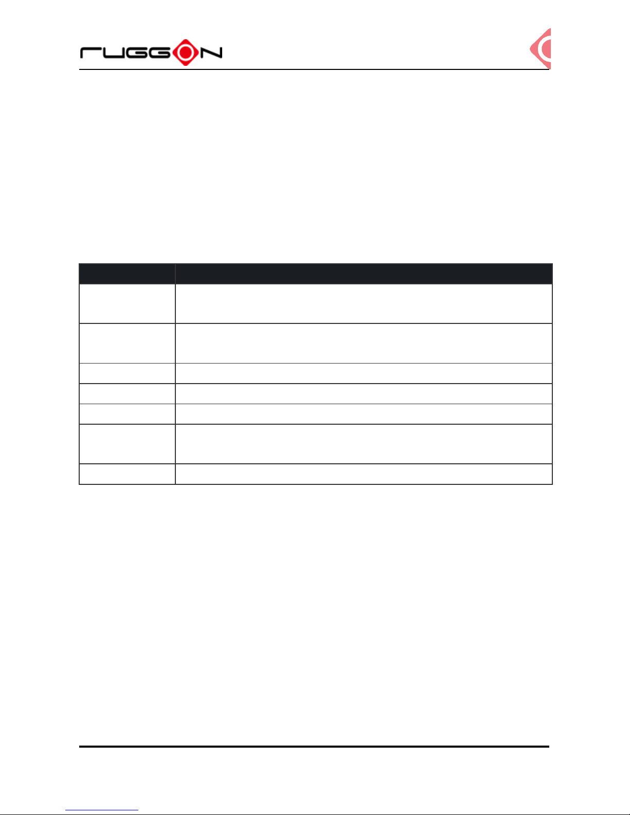
I/O Ports
Item
Description
Serial
RS-232 x 1 with 0/5/12V support 0.6A (COM1)
RS-232 TX, RX/422/485 x 1 (COM2)
USB
USB 3.0 x 1
USB 2.0 x 1
Ethernet
Gigabit RJ45 x 1
GPIO
2 DI + 2 DO
CAN
CANbus and SAE J1939/OBD II support
Audio
Headset jack x 1
Internal MIC-in x 1
Speaker
Waterproof speakers 3W
VX-601
V1.2
13
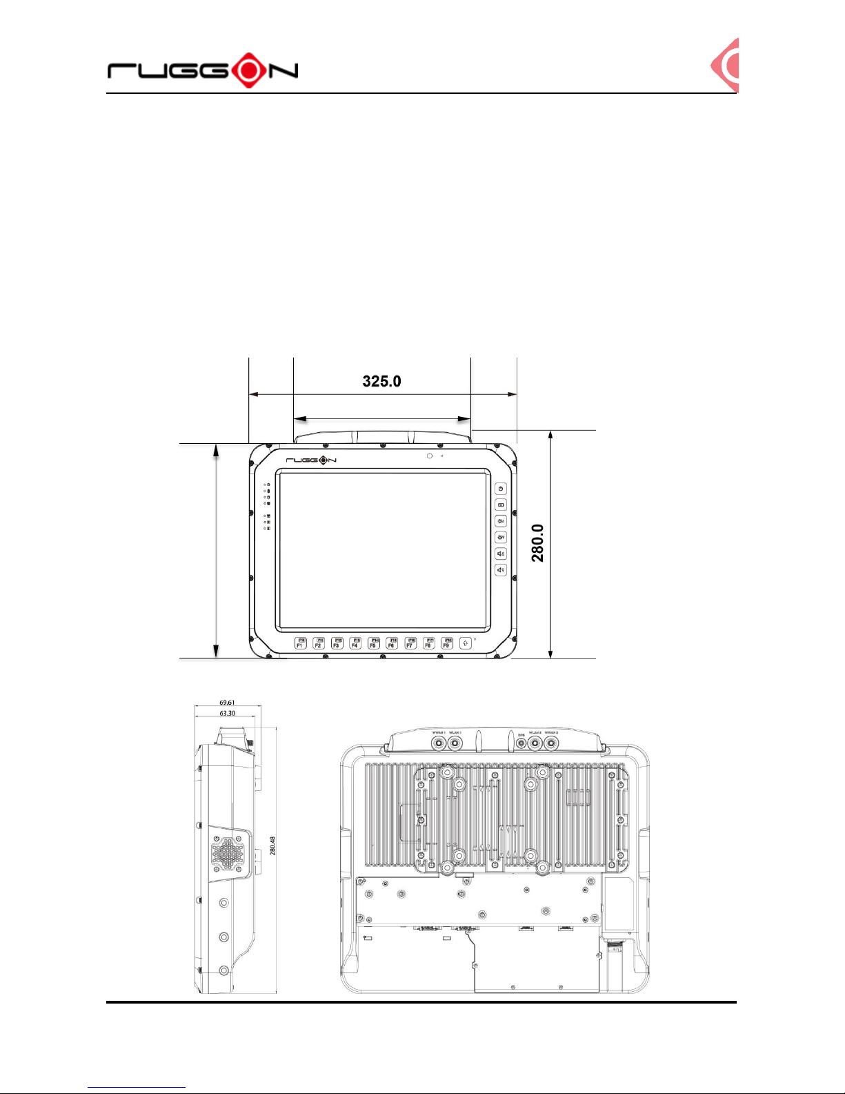
Dimension and Weight
VX-601 Standard
Dimension(w/ antenna cover): 325 x 280 x 67.3mm / 12.80 x 11.02 x 26.50in. (W x H x D)
Dimension(w/o antenna cover)325 x 262 x 67.3mm/ 12.80 x 10.31 x 26.50in. (W x H x D)
Weight: 4.83 kg/ 10.65 lbs.
Front View Dimension
Side View Dimension
223.0
262.0
VX-601
V1.2
14
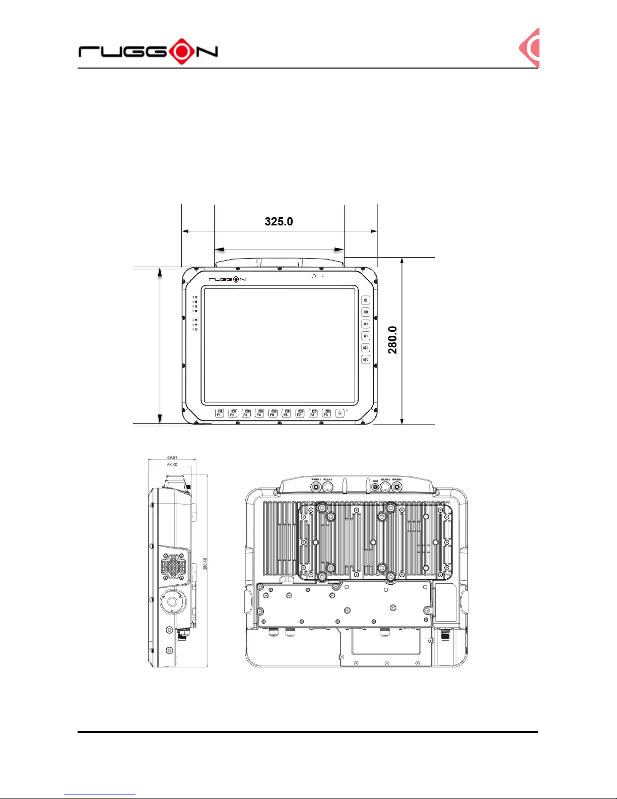
VX-601 with I/O water-proof box
Dimension(w/ antenna cover): 325 x 280 x 69.6 mm / 12.8 x 11.02 x 2.7in.(W x H x D)
Dimension(w/o antenna cover): 325 x 262 x 67.3mm/ 12.80 x 10.31 x 26.50in.(W x H x D)
Weight: 4.90 kg / 10.80 Ibs (with mSATA)
Front View Dimension
Side View Dimension
223.0
262.0
VX-601
V1.2
15
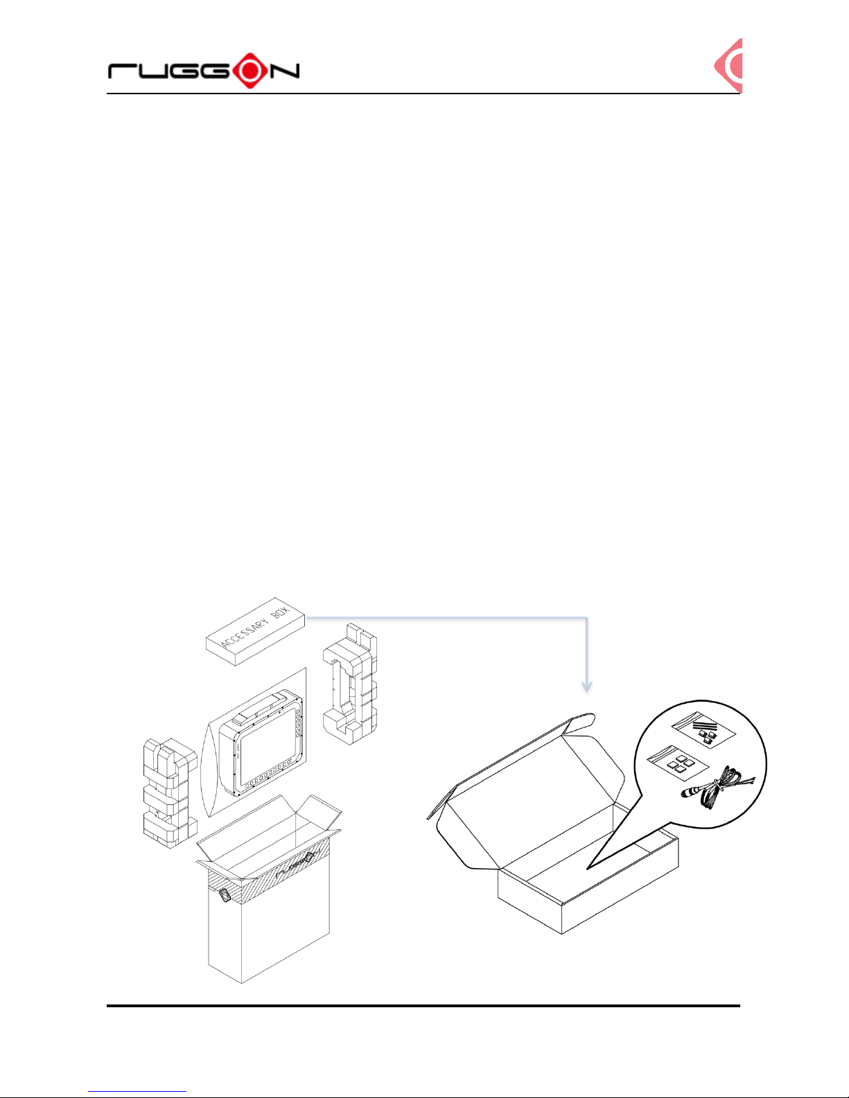
Package List
Before you begin the installation or configuration process make sure to inspect all
components and accessories. Contact your representative if there are any missing or
damaged items.
Please verify the delivery of the contents upon receipt
VX-601 vehicle mount computer
Accessory Box:
Bare wire power cable with circular power code
Thermal pad
Cable tie
NOTE: The packaging material has been selected to optimally protect your device. After
unpacking, store the original packaging material in the event that you need to return
shipment.
VX-601
V1.2
16
Chapter 2. Hardware Installation
This chapter provides information for the installation and removal of M.2 storage and mini
PCIe card.
M.2 Module
Prevention of EMI interference in this device is not guaranteed if the original components are
replaced.
A single M.2 2280 module slot is available for memory expansion. The device supports up to
256GB.
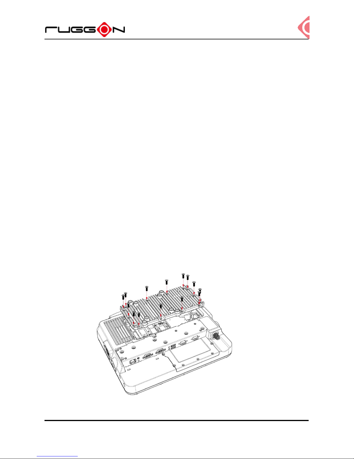
Installing/Removing a M.2 Module
1. Shut down the system properly and disconnect from all power sources.
2. Un-mount the device from the mounting apparatus; make sure that the display surface
is protected.
3. Remove the screws and the service cover.
VX-601
V1.2
17
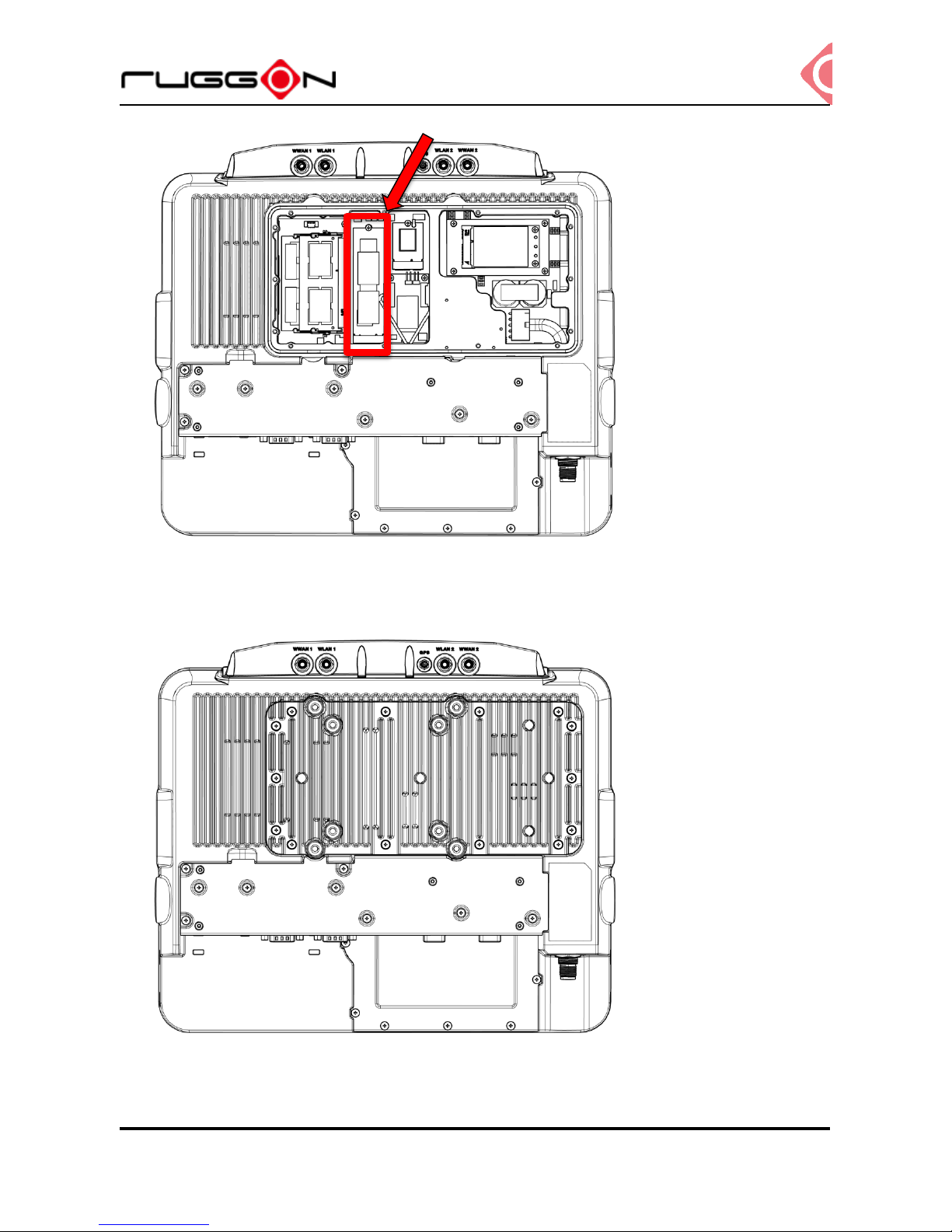
4. Locate the M.2 module slot, see the following image.
5. Insert the M.2 module into the slot and then Fasten the screws or Loosen the screws,
remove the card
6. Replace the service cover.
VX-601
V1.2
18
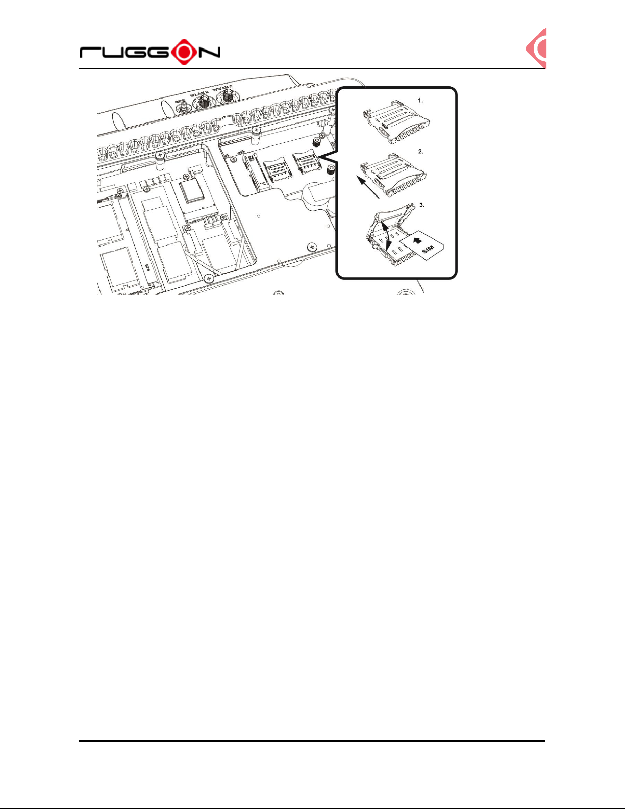
Installing/Removing the SIM card
VX-601 provides dual micro SIM slots, located inside the service door. Install the SIM card in
SIM 1 slot or SIM 2 slot. You can select different SIM slot via the SIM slot assignment option
in DashON interface. The factory default is SIM 1 slot. Please see the following guide to
install or remove the SIM card.
Internal SIM slot
1. Shut down the system properly and disconnect from all power sources.
2. Un-mount the device from the mounting apparatus; make sure that the display surface is
protected.
3. Remove the screws securing the cover and remove it.
4. Once the service cover is removed, you can see the Mini SIM card slot.
5. Slide to unlock the lock on the locking lid.
6. Lift the locking lid up and insert your SIM card.
7. Lock the locking lid back after insertion.
VX-601
V1.2
19
8. Turn your SIM card to the angled corner of your SIM card matches the angled corner of
the SIM card holder.
9. Insert the SIM card into the SIM card holder.
10. Close the cover of the SIM card holder.
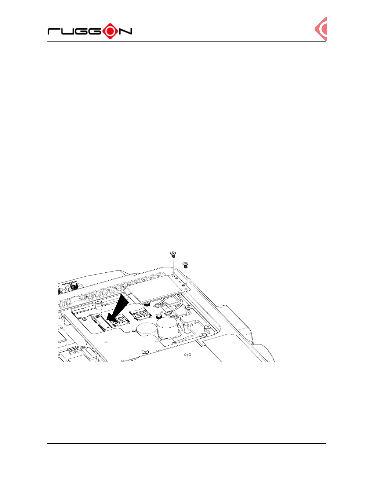
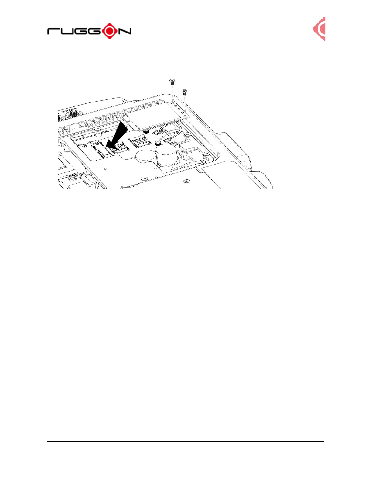
Installing/Removing the WWAN module
WWAN card slot is also located on the rear side; it is up to the Wi-Fi module. Please follow
up the introduction to install or remove the module
1. Power down the device and disconnect from all power source.
2. Un-mount the device from the mounting apparatus; make sure that the display surface is
protected.
3. Open the service cover; locate the WWAN module slot on the VX-601.
VX-601
V1.2
20
4. Install or remove the module.
Installing WWAN Antennas
After you installed the WWAN module, you need to connect the antenna for use. Please note
VX-601 support internal (optional) or external WWAN antenna. If you like to use the internal
or external WWAN antenna, you need to manually disable either one. The following section
will guide you how to change the internal/ external antenna.
External Antennas
1. Locate the antenna cables. (black cable & grey cable)
2. Use the black cable on the antenna cable and connect to the connector labeled MAIN.
Use the grey cable on the antenna cable to connect to the connector labeled AUX.
 Loading...