

RuggON PM-511 User Manual

User’s Manual
PM-511

PM-511 User Manual
1 |
Introduction
1. Please read these safety instructions carefully.
2. Please keep this User’s Manual for later reference.
3. Please disconnect this equipment from connecter before cleaning. Don’t use liquid
or prayed detergent for cleaning. User moisture sheet or cloth for cleaning.
4. Make sure the equipments are connected to the power source with the correct
voltage, frequency, and ampere.
5. All cautions and warnings on the equipment should be noted.
6. Never pour any liquid into opening: this could cause fire or electrical shock.
7. Never open the equipment. For safety reason, the equipment should only be opened
by qualified service personnel.
8. If one of the following situations arises, get the equipment checked by a service
personnel:
a. Liquid has penetrated into the equipment.
b. The equipment has been exposed to moisture.
c. The equipment has not worked well or you cannot get it work according to user
manual.
d. The equipment has dropped and damaged. If the equipment has obvious sign of
breakage.

PM-511 User Manual
2 |
9. Caution on use of battery: User the battery recommended by the manufacturer or
the same type of battery installed by the manufacturer. If incorrect battery is used,
it may cause explosion or fire hazard. Recycle or discard used batteries according
the manufacturer’s instruction or your local authority.
10. The computers use nonvolatile memory that requires a battery to retain system
information when power is removed. The 3V lithium battery is on the system board.
The battery life depends on the amount of time the computer is powered on. If the
computer does not display the correct time and date, replace the battery.
IMPORTANT:Loss of BIOS settings occurs when the battery is removed. BIOS settings
must be reconfigured whenever the battery is replaced.
WARNING:A risk of fire and chemical burn exists if the battery is not handled properly.
Do not disassemble, crush, puncture, or short external contacts, or expose the battery
to temperatures higher than 60 °C (140 °F). Do not dispose of a used battery in water
or fire.
CAUTION:Danger of explosion if battery is incorrectly replaced. Replace only with same
or equivalent type recommended by the manufacturer. Discard used batteries according
to the manufacturer’s instructions.
FCC Compliance Statement
This equipment has been tested and found to comply with the limits for a class B digital
device, pursuant to part 15 of the FCC Rules. These limits are designed to provide
reasonable protection against harmful interference in a residential installation.
This equipment generates uses and can radiate radio frequency energy and, if not
installed and used in accordance with the instructions, may cause harmful interference
to radio communications. However, there is no guarantee that interference will not
occur in a particular installation. If this equipment does cause harmful interference to
radio or television reception, which can be determined by turning the equipment off
and on, the user is encouraged to try to correct the interference by one or more of the
following measures:
-- Reorient or relocate the receiving antenna.
-- Increase the separation between the equipment and receiver.

PM-511 User Manual
3 |
-- Connect the equipment into an outlet on a circuit different from
that to which the receiver is connected.
-- Consult the dealer or an experienced radio/TV technician for help.
FCC Caution: Any changes or modifications not expressly approved by the party
responsible for compliance could void the user's authority to operate this equipment.
FCC RF Radiation Exposure Statement:
1. This Transmitter has been demonstrated co-location compliance requirements with
Wi-Fi, Bluetooth and RFID Modules. This transmitter must not be co-located or
operating in conjunction with any other antenna or transmitter.
2. This equipment complies with FCC RF radiation exposure limits set forth for an
uncontrolled environment. This device was tested for typical hand held operations
with the device contacted directly to the human body to the back side of the tablet pc.
To maintain compliance with FCC RF exposure compliance requirements, avoid direct
contact to the transmitting antenna during transmitting.
EEuurrooppee –– EEUU DDeeccllaarraattiioonn ooff CCoonnffoorrmmiitty
y
This device complies with the essential requirements of the R&TTE Directive
1999/5/EC and EMC directive 2004/108/EC. The following test methods have been
applied in order to prove presumption of conformity with the essential requirements of
the R&TTE Directive 1999/5/EC and EMC directive 2004/108/EC:
EN 55022: 2006 +A1: 2007
EN 61000-3-2 : 2006
EN 61000-3-3 : 1995 + A1 : 2001 + A2 : 2005
EN 55024: 1998 + A1: 2001 + A2: 2003
(IEC 61000-4-2: 2008;
IEC 61000-4-3: 2006 + A1:2007;
IEC 61000-4-4: 2004;
IEC 61000-4-5: 2005;
IEC 61000-4-6: 2003 + A1: 2004 +A2: 2006;
IEC 61000-4-8: 1993 +A1: 2000;
IEC 61000-4-11: 2004)
EN 60950-1: 2001
Safety of information technology equipment
EN 300 328 V1.7.1: 2006
EN 301 489-17 V2.1.1: 2009 and EN 301 489-1 V1.8.1: 2008
EN 62311: 2008
This device is a 2.4GHz wideband transmission system (transceiver), intended for use in

PM-511 User Manual
4 |
all EU member states and EFTA countries under the following conditions and/or with the
following restrictions:
In Italy the end-user should apply for a license at the national spectrum authorities
in order to obtain authorization to use the device for setting up outdoor radio links
and/or for supplying public access to telecommunications and/or network services.
This device may not be used for setting up outdoor radio links in France and in some areas the RF
output power may be limited to 10 mW EIRP in the frequency range of 2454 – 2483.5 MHz. For
detailed information the end-user should contact the national spectrum authority in France.

PM-511 User Manual
5 |
Table of Contents
Introduction ............................................................ 1
Table of Contents ................................................... 5
Chapter 1 ................................................................. 8
General Information ............................................... 8
1.1. Introduction.......................................................................................... 8
1.2. Specification ........................................................................................ 8
1.2.1. Main System ............................................................................................ 8
1.2.2. I/O Interface ............................................................................................. 9
1.2.3. In Front Control ........................................................................................ 9
1.2.4. Power Management ................................................................................. 9
1.2.5. Environment ............................................................................................. 9
1.2.6. Material .................................................................................................. 10
1.2.7. Operation OS ......................................................................................... 10
1.2.8. Certifications .......................................................................................... 10
1.2.9. Optional: Internal Module ....................................................................... 10
1.2.10. Optional: External Accessories ............................................................. 11
1.3. Packing List ....................................................................................... 12
Chapter 2 ............................................................... 13
System Setup ....................................................... 13
2.1. Exploring Your PM-511...................................................................... 13
2.1.1. The PM-511 IO ............................................................................... 13
2.2.Preparing for Installation ................................................................... 16
2.2.1.Switch ON the main battery .................................................................... 16
2.2.2.Plugging to the DC supply ...................................................................... 17
2.2.3.Starting Your System .............................................................................. 17

PM-511 User Manual
6 |
2.2.4.Connecting the keyboard and mouse ..................................................... 18
Chapter 3 ............................................................... 19
Using the PM-511 ................................................. 19
3.1.Introduction......................................................................................... 19
3.2.Using the USB Ports .......................................................................... 19
3.3.Using the External Audio System ..................................................... 19
3.4.Installing the Battery (optional) ........................................................ 19
3.5.Using a SIM Card .................................................................................... 20
3.5.1.Inserting a SIM Card ............................................................................... 20
3.5.2.Removing a SIM Card ............................................................................. 23
3.6.Using a Barcode Scanner Module, MSR, desktop Docking or Vehicle docking (optional) 24
Using the Docking Station ....................................................................... 25
The right side of the Docking Stand ................................................................. 25
The rear side of the Docking Station ................................................................ 26
Chapter 4 ............................................................... 34
The BIOS Setup Program .................................... 34
4.1.Main Screen Setup Utility .................................................................. 34
4.2.Advanced BIOS Features .................................................................. 36
4.3.Security Chip Configuration.............................................................. 36
4.4.Boot Management Setup ................................................................... 37
4.5.Exit Control ......................................................................................... 38
Chapter 5 ............................................................... 39
User Interface for PM-511 .................................... 39
5.1.Introduction......................................................................................... 39
5.2.About the User Interface .................................................................... 39
5.2.1.Enable or disable the User Interface ....................................................... 39
5.2.3.System Status Information ...................................................................... 39
5.3.Using the Application ......................................................................... 41
5.3.1.Brightness Control .................................................................................. 41

PM-511 User Manual
7 |
5.3.2.Volume Control ....................................................................................... 42
5.3.3.Webcam Launch ..................................................................................... 42
5.3.4.Monitor Switch ........................................................................................ 43
5.3.5.RF Device ON/OFF Control .................................................................... 43
Chapter 6 ............................................................... 45
Maintenance ......................................................... 45
6.1.Maintaining the Battery ...................................................................... 45
6.2.Maintaining the LCD Display ............................................................. 45
6.3.Cleaning the PM-511 .......................................................................... 45

PM-511 User Manual
8 |
CChhaapptteerr 1
1
General Information
11..11.. IInnttrroodduuccttiioonn
PM-511 rugged tablet PC is Intel® Cedar Trail Platform (N2600+NM10) processor core architecture based
rugged Tablet PC with a bright 10.4-inch LED backlight LCD display. The powerful CPU brings the most
dynamic applications to life without sacrifices to any industrial reliability.
Delivering a variety of connectivity features, built-in USBs, Microphone and Headphone port. It is ideal for
an all-around system performance. Furthermore, PM-511 rugged tablet PC is equipped with fanless design.
11..22.. SSppeecciiffiiccaattiioon
n
The PM-511 rugged tablet PC is a flexible, multi-functional flat tablet PC. With following specifications that
can be applied in diverse operational environments and implemented in multi-faceted applications.
1.2.1. Main System
Platform:
Intel® Cedar Trail Platform (N2600+NM10)
CPU:
Intel ATOM N2600 1.6GHz Dual core
Graphic:
Intel Graphics Media Accelerator 3600 series
Chipset:
Intel® NM10 Express Chipset
System Memory:
2GB DDRIII 800 SO-DIMM
Storage:
1 x 32GB SATA Slim Half-Size Solid State Disk
LCD Panel:
10.4-inch LED Backlight Screen
10.4“ XGA (1024x768) 350nits LCD + T/P(Polarizer + 1/4 λ+ AR)
10.4“ XGA (1024x768) 750nits LCD + T/P(Polarizer + 1/4 λ+ AR)
Touch Panel
5-wire Resistive Touch Screen

PM-511 User Manual
9 |
Audio:
-1 x High Quality Speaker (2W)
-Internal Microphone : 1 x in front Bezel
Communication :
- 10/100Mbps Ethernet
- Wi-Fi IEEE 802.11 a/b/g/n ; Bluetooth 4.0
Webcam:
Front - 2 Mega-pixel Camera
Rear - 5 Mega-pixel Camera with LED Flash light
1.2.2. I/O Interface
External I/O :
2 x USB 2.0 type A
1 x Audio Jack
1 x Ethernet jack
1 x Docking Connector
1 x DC-Jack
LED Status Indicator:
Power LED Status: 1 x Green/Red Colors
Storage LED Status: 1 x Blue Color
Wi-Fi LED Status: 1 x Blue Color
1.2.3. In Front Control
Switch :
1 x Power Button
1 x Lock Button
1 x RF Button
Button :
Program Function Buttons : 6 x Function keys (Programmable)
1.2.4. Power Management
Power Adapter :
AC to DC, 19VDC@3.42A, 65W
AC 100V ~ 240V, 50~60Hz input
19 DC-in
Battery (Internal Battery) :
Internal Smart Lithium Polymer Battery, 3800mAh (2S1P), 7.4V
1.2.5. Environment
Operation Temperature :
-10°C to +50°C (MIL-STD-810G Method 501.5 and 502.5)

PM-511 User Manual
10 |
Storage Temperature :
-20°C to +70°C (MIL-STD-810G Method 501.5 and 502.5)
Humidity :
5-95% without condensation (MIL-STD-810G Method 507.5)
Drop :
6-ft drop to Plywood (MIL-STD-810G Method 516.6 Procedure IV)
Vibration :
Operating : SSD (MIL-STD-810G Method 514.6 Category 4 Fig 514.6C-3)
Mechanical Shock :
Operating : 20g, 11ms, Terminal sawtooth
Non-operating : 40g, 11ms, Terminal sawtooth (MIL-STD- 810G Method 516.6 Procedure I)
Water/Dust Resistance : IP65 equivalent
1.2.6. Material
Chassis :
RUGGED Tablet PC Slate
Enclosure :
PC/ABS Plastic, PC/ABS and TPU Double Injection with Protective Rubber Grips Set
Dimension (W x H x D mm) :
277.8 x 206 x 26.5mm
Weight :
Approximate 1.2kg (with internal battery)
1.2.7. Operation OS
WIN7 PRO
WES7-WS7P
1.2.8. Certifications
EMI :
FCC part 15 Class B
VCCI (V-3/V-4)
CE (EN55022 / EN55024)
Safety :
UL (EN60950), CE
RF :
FCC part 15 subpart C
SAR :
FCC SAR (OET 65 C)
1.2.9. Optional: Internal Module
3.5G Sierra MC8355 Gobi3000 :

PM-511 User Manual
11 |
Protocol :
HSUPA/HSDPA/UMTS/EVDO/EDGE
Frequency :
UMTS/HSUPA/HSDPA 850/900/1800/2100MHz
CDMA/EVDO 800/1900MHz
GSM/GPRS/EDGS 850/900/1800/1900MHz
1.2.10. Optional: External Accessories
MSR :
Reference Standards :
ANSI/ISO Standards 7810,7811-1/6, 7813
JIS II
Decoding Method :
ISO Track1 - IATA , Track2 - ABA and Track3 – THRIFT
Barcode Scanner :
Decoded Mode :
1D Symbologies : EAN/UPC, RSS, Code 39, Code 128, UCC/EAN 128, ISBN, ISBT, Interleaved,
Matrix, Industrial and Standard 2 of 5, Codabar, Code 93/93i, Code 11, MSI, Plessey, Telepen, postal
codes.
2D Symbologies: Data Matrix, PDF417, Micro PDF 417, Maxicode, QR, Aztec, EAN.UCC composite.
GPS :
Channel :
50 channel all-in-view tracking
GPS or GLONASS support
1 x Signal Color LED (Blue)
Desktop Docking :
4 x USB2.0 type A, 1 x Ethernet, 1 x HDMI, 1 x VGA, 1 x Kensington lock and 1 x DC Jack support
External Battery Kits :
External Battery Pack :
Hot-swappable Lithium Polymer battery pack - doubles duration of mobile operation, 4200mAh (2S1P),
7.4V
External Battery Charger :
Recharges external battery pack
Vehicle Application Accessories :
Vehicle Mounting Docking :
4 x USB2.0 type A, 2 x RS232, 1 x 10/100Mbps Ethernet, 1 x VGA and DC-Jack support
75 x 75/100 x 100mm Vesa Mount Holes support
6VDC to 36VDC Input (6VDC to 36VDC for Momentary and 9VDC to 32VDC for Normal)
19 V@1.57A Max., total output 30W
PM-511 User Manual
12 |
Cigarette lighter plug power cord
ACC power cord (option)
GPS (option)
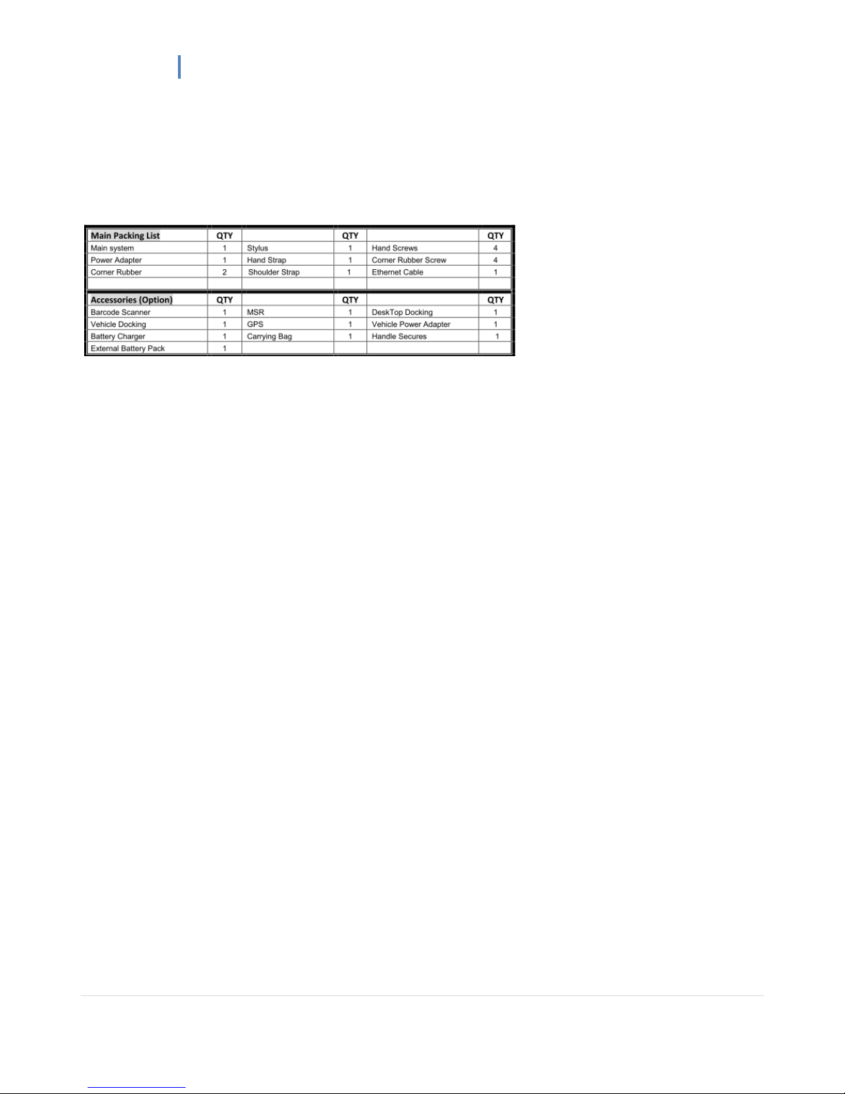
11..33.. PPaacckkiinngg LLiisstt
PM-511 User Manual
13 |
CChhaapptteerr 2
2
System Setup
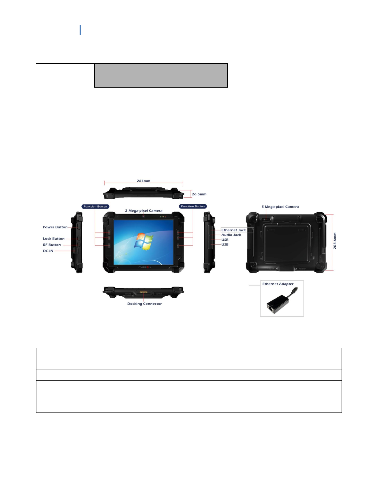
22..11.. EExxpplloorriinngg YYoouurr PPMM--551111
Before starting to set up the PM-511, get familiar with the locations and purpose of controls, connectors and I/O ports,
which are illustrated in the figures below. When placed upright, the front panel of the PM-511 appears as shown in
below.
2.1.1. The PM-511 IO
The PM-511 I/O is as described below.
F1 Button
F1=explorer
F2 Button
F2=Windows Media Player
F3 Button
F3=OnScreen keyboard
F4 Button
F4=Task Manager
F5 Button
F5=Calculator
Fn Button
Fn = Hotkey Utility
 Loading...