


PA501
User's Manual

©2019 RuggON Corporation. All rights reserved.
TRADEMARKS
RuggON logo is a trademark of RuggON Corporation, re
gistered in the United States Patent and
Trademark Office and in other countries. Microsoft and the Windows logo are either registered
trademarks or trademarks of Microsoft Corporation in the United States and/or other countries.
Microsoft products are licensed to OEMs by Microsoft Licensing, Inc., a wholly owned subsidiary of
Microsoft Corporation. The Bluetooth® word mark and logos are registered trademarks owned by
Bluetooth SIG, Inc. All other brand and product names are trademarks or registered trademarks of
their respective owners.
Images shown in this document may vary slightly from
actual products at time of shipping.
Information in this manual is subject to change without notice.

Table of Contents
About This Manual
Related Information ..................................................................................... 1
Conventions ........................................
Basic Safety Guidelines
Intended Use ............................................................................................... 2
Maintenance and Operation Overview ........................................................ 2
Safety ......................................................................................................... 3
Electrical Hazards ....................................................................................... 3
Environmental ......................................
Radio Transmissions ................................................................................... 4
Cleaning and Servicing ............................................................................... 4
Regulatory and Certification ........................................................................ 4
Lithium Battery Safety Statement ............................................................... 5
Chapter 1. Introduction
About This Guide ........................................................................................ 6
........................................................ 1
....................................................... 3
Unpacking the Device ................................................................................. 6
Technical Specifications ..............................................................................7
PA501 Configuration Options ...................................................................... 8
Parts List .................................................................................................... 9
Identifying the Device ................................................................................ 10
Dimensions .........................................
Chapter 2. Getting Started
First Time Use .......................................................................................... 14
Charging the Battery ................................................................................. 14
Powering the Device On and Off .............................................................. 15
Installing the Micro SIM 2 Card.....................
Removing the Micro SIM 2 Card................................................................16
Removing the Protective Film from the Display ......................................... 17
...................................................... 13
.............................................16
Chapter 3. Operation
Opening the I/O Compartment Cover ........................................................ 18
i

Closing the I/O Compartment Cover .......................................................... 19
Connecting to External Cabling ................................................................. 20
Handstrap, Carrying Handle and Shoulder Strap....................................... 22
Installing the Standard Battery ................................................................. 24
Removing the Standard Battery ............................................................... 25
Connecting to a Wireless Network ...................
Chapter 4. Apps and setttings
Troubleshoot the Wi-Fi Connection ........................................................... 28
Troubleshoot Operating the Computer ...................................................... 29
Call Product Support ................................................................................. 29
Chapter 5. RuggON DashON Utility
Troubleshoot the Wi-Fi Connection ........................................................... 28
Troubleshoot Operating the Computer ...................................................... 29
Chapter 6. Troubleshooting
Troubleshoot the Wi-Fi Connection ........................................................... 28
Troubleshoot Operating the Computer ................
Call Product Support ................................................................................. 29
.......................................... 27
...................................... 29
Chapter 7. Maintenance
Cleaning the Device .................................................................................. 30
Returning the Device ................................................................................. 30
Contacting RuggON ..................................
................................................ 30
ii
About This Manual
The PA501 User’s Manual provides instruction for qualified personnel to follow when setting up a
new PA501 device.
This document is intended for use by qualified personnel to compliment the training and expertise,
not to replace it.
Related Information
Current information and manuals are available for download at the following website:
http://www.ruggon.com
Conventions
Bolded or underlined text is used to emphasize the designated information.
A Note is used to provide additional information for the device or settings.
A Caution is used to warn against potential hazards or to caution against unsafe
practices.
A Warning is used to identify immediate hazards for property damage, injury or death.
1

Basic Safety Guidelines
The following safety guidelines are intended to help protect the user from injury and prevent
damage to the hardware.
■
Do not place anything on the AC adapters power cable and make sure the cable is not
located where it can be tripped over or stepped on.
■
Do not cover the AC adaptor as it reduces the cooling.
■
Do not use the AC adapter while it is inside the carrying case.
■
Use only the AC adapter, power cord, and batteries that are approved for use with the device.
Use of another type of battery or AC adapter may cause risk of fire or explosion.
■
If you use an extension cable with the AC adapter, ensure that the total ampere rating of
all products plugged in to the extension cable does not exceed the ampere rating of the
extension cable.
■
If the device is moved between environments with very different temperature and/ or humidity
ranges, condensation may form on or within the device. Avoid damaging the device by
allowing sufficient time for the moisture to evaporate before using the device.
■
When disconnecting cables, pull on the connector or on its strain relief loop, not on the
cable itself. When pulling out or plugging in the connector, keep it evenly aligned to prevent
bending the connector pins.
Intended Use
The PA501 rugged tablet is equipped with multi-functional terminals for stationary and
mobile applications in industrial environments such as logistics, warehousing, fleet
management, manufacturing and the automotive industry.
Read the safety guidelines thoroughly before starting any servicing on the device. Read the
guidelines before powering up the device, and keep this document for later use.
The operator is solely responsible for any damage resulting from unauthorized modifications to the
device.
Unintended Application Use
The device is not designed for use in life-support systems or critical safety/security systems where
system malfunction can lead to the direct or indirect endangerment of human life. The operator is
fully responsible for using the device in these situations.
Maintenance and Operation Overview
The PA501 is designed and manufactured according to strict controls and following the stated
safety regulations. The following list identifies incorrect operating uses of the PA501. Incorrect
use of the PA501 can lead to hardware damage, safety issues and possible risk to personnel
health:
■
The PA501 is under operation by untrained personnel;
■
The PA501 is not maintained as recommended;
■
The PA501 is not used as intended.
2

Safety
To prevent injury and damage, read the following safety guidelines prior to operating the
device. The manufacturer assumes no liability for any and all damages arising from misuse or
noncompliance with these guidelines.
Electrical Hazards
Cleaning/Servicing: Power Off the PA501
■
Disconnect the PA501 from power before cleaning or servicing it.
Power Adapter
Contact an authorized service personnel for repairs to the power pack. In the event of a blown
fuse after replacing the fuse, contact an authorized service personnel to avoid electrical shock.
Use only Supplied Power Cables
RuggON power cables meet industrial requirements for low-temperature flexibility, UV resistance,
and oil resistance. Use only supplied power cables from RuggON.
If other power cables are used, the following may apply:
■
The operator is solely responsible for the resulting damage;
■
All RuggON warranties are void.
Environmental Hazards
Do not use the PA501 in locations near/with flammable gases or vapor. The
use of electrical equipment in explosive environments can be dangerous.
■
Turn off the device when near a gas station, fuel depot, chemical plant or a place where
blasting operations take place.
Environmental
Ambient Temperature
The PA501 operates on the basis of a fanless concept which internal waste heat is
released via the housing surface and requires fresh airflow in the environment.
■
Operating the PA501 with no fresh cooling air may cause overheating and damage to the
device.
■
The operating environment should not be enclosed to prevent the cool air being heated by
the heat waste from the device.
Connecting and Disconnecting External Devices
To prevent the considerable damage, the PA501 and the external device should be disconnected
from power when connecting/disconnecting excluding USB devices.
Only Use Authorized Accessories
Only use the supplied cables, power packs and other accessories that have been tested and
approved by RuggON. Contact your local distributor for further information.
3

Radio Transmissions
Permitted Transmission Power
Follow the national regulations for the maximum permitted transmission power.
The operator is solely responsible for this type of operation.
Radio Frequency Limited Locations
Considering the radio frequency limitation in hospitals and aircraft, the PA501 can only
be installed with permission.
Industrial computers may affect the function of implanted medical devices such as pacemakers
and may cause malfunction.
Cleaning and Servicing
■
Disconnect the PA501 from power before cleaning or servicing.
■
Never clean the PA501 with compressed air, a pressure washer or a vacuum cleaner.
■
If necessary, clean the housing of the PA501 with a damp cloth.
■
Clean the touch-screen with a nonabrasive cloth.
Regulatory and Certification
Canada
IC No.: 25233-PA501B
Contains IC No.: 25233-MS01PRO
This digital apparatus does not exceed the Class B limits for radio noise emissions from digital
apparatus as set out in the radio interference regulations of the Canadian Department of
Communications.
Le présent appareil numérique n'émet pas de bruits radioélectriques dépassant les limites
applicables aux appareils numériques de Classe B prescrites dans le règlement sur le brouillage
radioélectrique édicté par le Ministère des Communications du Canada.
Changes and modifications not expressly approved by the manufacturer or registrant of this
equipment can void your authority to operate this equipment under Industry Canada rules.
Les changements et modifications non expressément approuvés par le fabricant ou le détenteur
de cet
équipement peuvent annuler votre droit à utiliser cet appareil en vertu des règles d'Industrie
Canada.
Antenna Statement
Under Industry Canada regulations, this radio transmitter may only operate using an antenna of
a type and maximum (or lesser) gain approved for the transmitter by Industry Canada. To reduce
potential radio interference to other users, the antenna type and its gain should be so chosen
that the equivalent isotropically radiated power (e.i.r.p.) is not more than that necessary for
successful communication.
Conformément à la réglementation d'Industrie Canada, le présent émetteur radio peut
fonctionner avec une antenne d'un type et d'un gain maximal (ou inférieur) approuvé pour
l'émetteur par Industrie Canada. Dans le but de réduire les risques de brouillage radioélectrique
à l'intention des autres utilisateurs, il faut choisir le type d'antenne et son gain de sorte que la
4

puissance isotrope rayonnée équivalente (p.i.r.e.) ne dépasse pas l'intensité nécessaire à
l'établissement d'une communication satisfaisante.
Licence exempt
This device complies with Industry Canada licence-exempt RSS standard(s). Operation is
subject to the following two conditions:
this device may not cause interference, and
this device must accept any interference, including interference that may cause undesired
operation of the device.
Le présent appareil est conforme aux CNR d'Industrie Canada applicables aux appareils radio
exempts de licence. L'exploitation est autorisée aux deux conditions suivantes :
l'appareil ne doit pas produire de brouillage, et
l'utilisateur de l'appareil doit accepter tout brouillage radioélectrique subi, même si le brouillage
est susceptible d'en compromettre le fonctionnement.
This Class B digital apparatus complies with Canadian ICES- 003.
Cet appareil numérique de la classe B est conforme à la norme NMB-003 du Canada.
This Category II radio communication device complies with Industry Canada Standard RSS-310.
Ce dispositif de radiocommunication de catégorie II respecte la norme CNR-310 d’Industrie
Canada.
IMPORTANT NOTE: IC Radiation Exposure Statement
This EUT is compliant with SAR for general population/uncontrolled exposure limits in IC RSS102 and had been tested in accordance with the measurement methods and procedures
specified in IEEE 1528. SAR is measured with the device at 0 mm to the extremity, while
transmitting at the highest certified output power level in all frequency bands of the device.
This equipment should be installed and operated with a minimum distance of 0 cm between the
radiator and your extremity. This device and its antenna(s) must not be co-located or operating in
conjunction with any other antenna or transmitter. The County Code Selection feature is disabled
for products marketed in the US/Canada.
IC SAR warning
Radio Frequency (RF) Exposure Information
The radiated output power of the Wireless Device is below the Industry Canada (IC) radio
frequency exposure limits. The Wireless Device should be used in such a manner such that the
potential for human contact during normal operation is minimized.
This device has been evaluated for and shown compliant with the IC Specific Absorption Rate
(“SAR”) limits when installed in specific host products operated in portable exposure conditions.
Informations concernant l'exposition aux fréquences radio (RF)
La puissance de sortie émise par l’appareil de sans fil est inférieure à la limite d'exposition aux
fréquences radio d'Industry Canada (IC). Utilisez l’appareil de sans fil de façon à minimiser les
contacts humains lors du fonctionnement normal.
Ce périphérique a été évalué et démontré conforme aux limites SAR (Specific Absorption Rate –
Taux d'absorption spécifique) d'IC lorsqu'il est installé dans des produits hôtes particuliers qui
fonctionnent dans des conditions d'exposition à des appareils portables.
The device could automatically discontinue transmission in case of absence of information to
5

transmit, or operational failure. Note that this is not intended to prohibit transmission of control or
signaling information or the use of repetitive codes where required by the technology.
The device for the band 5150-5250 MHz is only for indoor usage to reduce potential for harmful
interference to co- channel mobile satellite systems; the maximum antenna gain permitted (for
devices in the bands 5250-5350 MHz and 5470-5725 MHz) to comply with the e.i.r.p. limit; and
The maximum antenna gain permitted (for devices in the band 5725-5850 MHz) to comply with
the e.i.r.p. limits specified for point-to-point and non-point-to-point operation as appropriate, as
stated in section A9.2(3). In addition, High- power radars are allocated as primary users
(meaning they have priority) of the band 5250-5350 MHz and this radar could cause interference
and/or damage to LE-LAN devices.
FCC
FCC ID: 2ABTU-PA501B
Contains FCC ID:2ABTU-MS01PRO
This equipment has been tested and found to comply w
pursuant to part 15 of the FCC Rules. These limits are designed to provide reasonable protection
against harmful interference when the equipment is operated in a commercial environment.
This equipment generates, uses, and can radiate radio frequency energy and, if not installed and
used in accordance with the instruction manual, may cause harmful interference to radio
communications. Operation of this equipment in a residential area is likely to cause harmful
interference in which case the user will be required to correct the interference at his own expense.
However, there is no guarantee that interference will not occur in a particular installation. If
this equipment does cause harmful interference to radio or television reception, which can be
determined by turning the equipment off and on, the user is encouraged to try to correct the
interference by one or more of the following measures:
■
Reorient or relocate the receiving antenna.
■
Increase the separation between the equipment and receiver.
■
Connect the equipment into an outlet on a circuit different from that to which the receiver is
connected.
■
Consult the dealer or an experienced radio / TV technician for help.
Any changes or modifications not expressly approved by the grantee of this device could void the user’s
authority to operate the equipment.
ith the limits for a Class B digital device,
This device is operation in 5.15 – 5.25GHz frequency range, then restricted in indoor use only, Outdoor
operations in the 5.15 – 5.25GHz is prohibit.
This device is slave equipment; the device is not radar detection and not ad-hoc operation in the DFS
band.
6

Labeling Requirements
This device complies with Part 15 of the FCC Rules. Operation is subject to the following two
conditions: (1) this device may not cause harmful interference, and (2) this device must accept any
interference received, including interference that may cause undesired operation.
Users are able to access information in a device’s settings.
Settings->System->Regulatory information
1. Turn on your device
2. Draw down form top side of device
3. Tap settings icon
4. Slide down and choose system
5. Slide down and choose Regulatory information
RF Exposure Information (SAR)
This device meets the government’s requirements for exposure to radio waves. This device is
designed and manufactured not to exceed the emission limits for exposure to radio frequency (RF)
energy set by the Federal Communications Commission of the U.S. Government.
The exposure standard employs a unit of measurement known as the Specific Absorption Rate,
or SAR. The SAR limit set by the FCC is 1.6 W/kg. Tests for SAR are conducted using standard
operating positions accepted by the FCC with the EUT transmitting at the specified power level in
different channels.
CE Marking
This product has passed the CE test for environmental specifications when shielded cables are
used for external wiring. We recommend the use of shielded cables. Please contact your local
representative for ordering information.
This product has passed the CE test for environmental specifications. Test conditions for passing
included the equipment being operated within an industrial enclosure. In order to protect the
product from being damaged by ESD (Electrostatic Discharge) and EMI leakage, we strongly
recommend the use of CE-compliant industrial enclosure products.
European declaration of conformity
According to ISO / IEC Guide 22 and EN 450 14
Manufacturer’s Name: RuggON Corporation
5

Manufacturer’s Address: 4F, No.298, Yang Guang St., Neihu Dist., Tapipei City, Taiwan
Declares, under our sole responsibility, that the product: Product Name: Rugged Tablet
Model Number: PA501B
Conforms to the following Product Specifications:
- RED 2014/53/EU LVD 2014/35/EU EMC 2014/53/EU RED
- ETSI EN 301 511
-
ETSI EN 301 908-1
- ETSI 301 489-1
- ETSI 301 489-52
- ETSI EN 301 489-1
- ETSI EN 301 489-3
- ETSI 300 330
- ETSI EN 303 413
- ETSI EN 301 489-19
- ETSI EN 300 328
- ETSI EN 300 893
- ETSI EN 301 489-17
- EN 55032: 2015+AC: 2016
- EN 55035: 2017
- EN 55024: 2010+A1:2015
- EN 60950-1:2006/A11:2009 /A1:2010/A12:2011/A2:2013
Supplementary information
In addition, the product is battery powered and the power supply provided with this
product has been certified to IEC 60950-1: 2005 2nd edition +Am1:2009+Am2: 2013. As
manufacturer, we declare under our sole responsibility that the equipment follows the
provisions of the Standards stated above.
Importer of Record
CAUTION - Only approved accessories may be used with this equipment. In general, all
cables must be high quality, shielded, correctly terminated and normally restricted to two
meters in length. Power supplies approved for this product employ special provisions to
avoid radio interference and should not be altered or substituted. Unapproved
modifications or operations beyond or in conflict with these instructions for use may void
authorization by the authorities to operate the equipment.
This RuggOn product has been tested and found to comply with all requirements for CE
Marking and sale within the European Economic Area (EEA). The device has Bluetooth
and wireless LAN approval and satisfies the requirements for Radio and
Telecommunication Terminal Equipment specified by European Council Directive
2014/53/EU. These requirements provide reasonable protection against harmful
interference when the equipment is operated appropriately in a residential or commercial
environment.
6

The device is intended for connection to European Networks
a. Caution:
Risk of explosion if battery replaced by an incorrect type.
Dispose of used batteries according to the instructions.
b. Make sure the temperature for adapter will not be higher than 40 ˚C.
CE RF Power Table
5

Lithium Battery Safety Statement
Lithium battery inside. Danger of explosion if battery is incorrectly replaced. Replace only with same or
equivalent type recommended by battery manufacturer.
Lithium-Ion batteries are classified by the U. S. Federal Government as nonhazardous waste and are safe for disposal in the normal municipal waste stream.
These batteries contain recyclable materials and are accepted for recycling. Dispose
of used batteries in accordance with local regulations.
WARNING – Non-approved batteries will not function in the device. Use only the
battery for the system for which it was specified. Only use the battery with a charging
system that has been qualified with the system per this standard. Use of an
unqualified battery or charger may present a risk of fire, explosion, leakage, or other
hazard.
WARNING – There are no user-serviceable parts in the batteries. Do not
disassemble or open, crush, bend or deform, puncture, or shred the battery. Do not
modify or remanufacture, attempt to insert foreign objects into the battery, immerse or
expose to water or other liquids, or expose to fire, explosion, or other hazard. Do not
expose to temperatures above +60 °C (+140 °F).
WARNING – Improper battery use may result in a fire, explosion, or other hazard.
6

Do not short circuit a battery or allow metallic or conductive objects to contact
the battery terminals.
Avoid dropping the device or battery. If dropped, especially on a hard surface,
and the user suspects damage to the battery, take it to a service center for
inspection.
In the event of a battery leak, do not allow the liquid to come in contact with the
skin or eyes. If contact has been made, wash the affected area with large
amounts of water and seek medical advice.
Battery usage by children should be supervised.
Power supply safety
WARNING – Use only AC and vehicle adapters intended for the device.
Output rating 19 Vdc, minimum 3.42A. Other external power sources may
damage your product and void the warranty.
Ensure the input voltage on the adapter matches the voltage in your location.
Ensure the Class I adapter has prongs compatible with your outlets and earthing
connection.
The AC power supply is designed for indoor use only. Avoid using the AC power
supply in wet areas.
Unplug the power supply from power when not in use.
Do not short the output connector.
5

Introduction
Chapter 1. Introduction
The PA501 is a rugged device equipped with 802.11, Bluetooth and GNSS for wireless data
communications.
The PA501 is a rugged 10.1” tablet computer capable of 1920 x 1200
resolution. The PA501 supports the following operating systems:
■
Android 9.0 (Pie) with Google Mobile Services(GMS) certified
About This Guide
The PA501 User Manual provides instruction for qualified personnel to use as a guide for setup
of the device. This document is not intended to replace the training and expertise of the end-user.
Unpacking the Device
Before you begin the installation or configuration process make sure to inspect all components
and accessories. Contact your representative if there are any missing or damaged items. See
“Contacting RuggON” on page 30.
Technical Specifications
Table 1. Technical Specifications
Item Description
Display 10.1-inch LED Backlight, WUXGA 1920 (W) x 1200 (H)
Touch screen
Brightness
CPU
Operating System
RAM
Storage
Battery
Power Supply AC 100V ~ 240V, 50~60Hz input; 19VDC@3.42A, 65W
Dimensions (W x H x L) 280 mm (11”) x 23 mm (0.9”) x 195 mm (7.7”)
10-point capacitive touch screen
1000 nits TFT LCD
Qualcomm Snapdragon 660 Octa-core 1.9GHz up to 2.2GHz
Android 9.0 (Pie) with GMS certified
LPDDR4 3GB
eMMC 32GB
Standard hot swappable battery: 10.8V, 4500mAh, Li-polymer
■
Extended hot swappable battery: 10.8V, 9000mAh, Li-polymer
■
(optional)
Weight 1.4 kg (3.09 lbs)
6

Introduction
Item Description
Wireless
WLAN Wi-Fi IEEE 802.11 a/b/g/n/ac
Bluetooth Bluetooth v5.0 class1
WWAN Option 4G LTE
Sensor
Sensor Gyroscope, G Sensor, E-compass, Light Sensor
I/O
Docking Connector 30-pin
DC-IN Jack x1
Micro SIM Card Slot x2
Audio Jack x1; headphone / microphone combo
USB x3; USB2.0 type A x2, USB 3.1 type C x 1 (Display port supported)
RS-232 x1 (Available for option USB 2.0)
Micro SD x1
Ethernet x1
Security ARM® TrustZone®
Data Collection
Camera
Front: 8 MP camera
■
Rear: 13 MP camera with LED flash and Auto-focus
■
GNSS YES
NFC Optional
Barcode Reader Optional
Fingerprint Reader Optional
7

Introduction
Item Description
Rugged Specifications
Drop 153 cm (5 feet), 26 drops on plywood
MIL-STD 810G
Vibration (MIL-STD-810G Method 514.7 Category 4,
■
Fig 514.7C-2, Fig 514.7C-3, Fig 514.7C-4)
Drop (MIL-STD-810G Method 516.7 Procedure IV)
■
Mechanical shock
■
(MIL-STD-810G Method 516.7 Procedure I, Procedure V)
Operation and storage temperature
■
(MIL-STD-810G Method 501.6 and 502.6)
Humidity MIL-STD-810G Method 507.6 Humidity Procedure II
■
Aggravated Cycles (Fig 507.6-7)
IP rating IP65
Operating Temperature
Range
Storage Temperature
Range
-20°C (-4°F) to 60°C (140°F)
-30°C (-22°F) to 70°C (158°F)
Humidity 5-95% without condensation
PA501 Configuration Options
The following options are available for the PA501:
■
Built-in NFC module
■
Built-in 2D barcode reader (OCR supported)
■
High capacity battery
■
Fingerprint reader
■
Snap-on connector easy for customization
8
Introduction
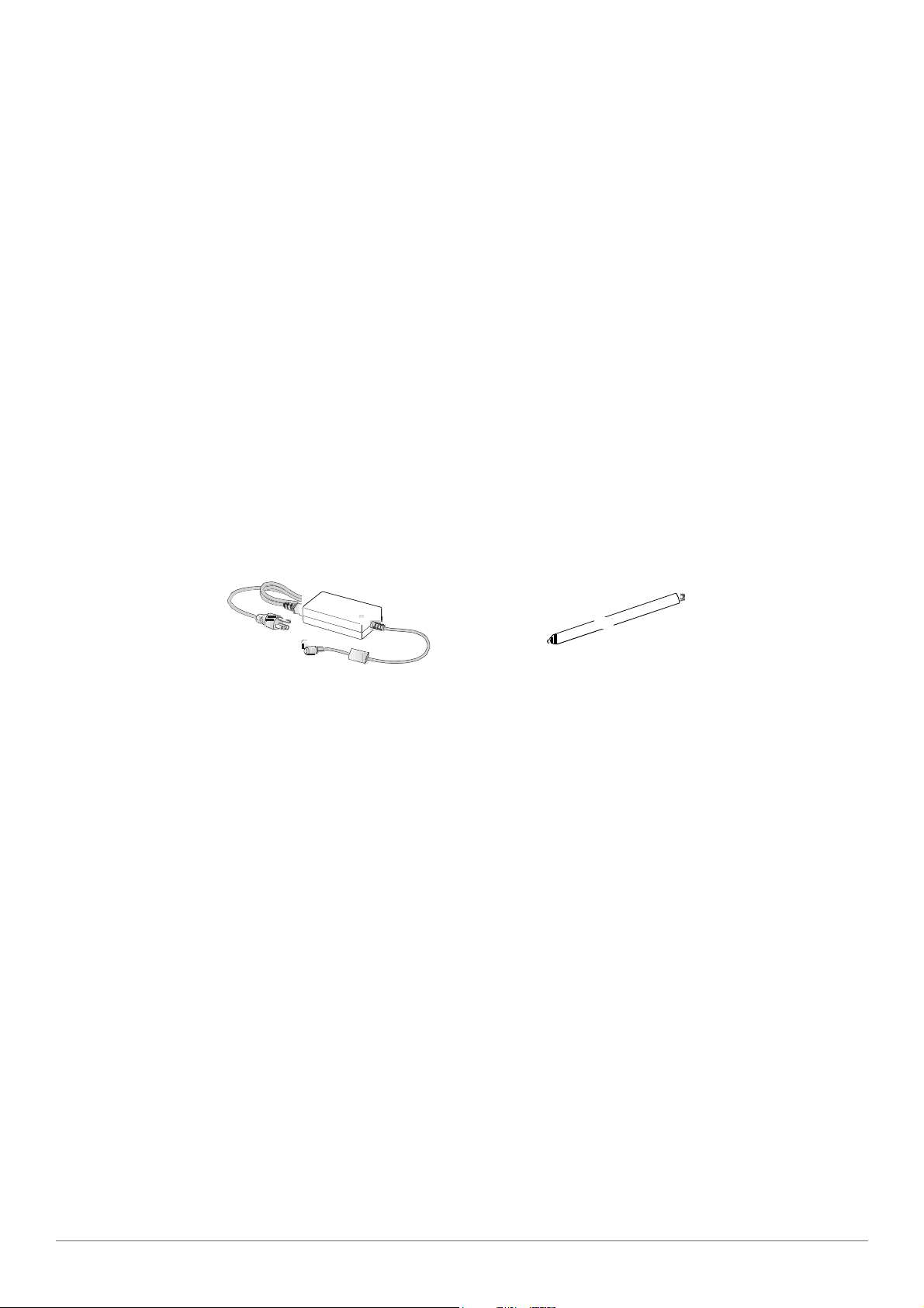
Parts List
The PA501 is shipped with the following items. All other accessories are sold and ordered
separately. For help, contact your local RuggON sales representative. See “Contacting RuggON”
on page 30.
PA501
Power Adapter Stylus
9
fn
f1 f2
fn
3
Introduction
Identifying the Device
Overview
Overview
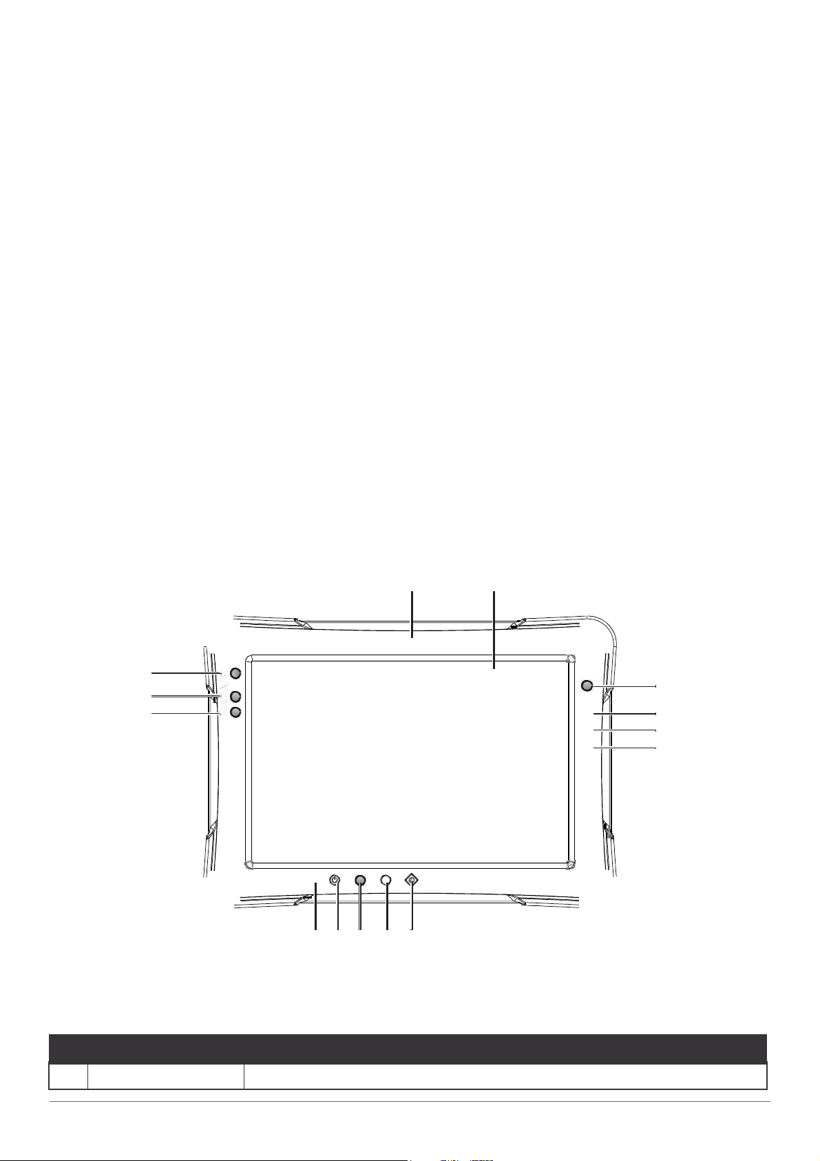
Front View
14
13
12
1 2
11 10 9 8 7
Figure 2. Front View
4
5
6
Table 3. Front View
No
1
Front camera 8.0 Mega-Pixels camera.
10
Item Description

2
Touch screen 10-point capacitive touch.
3
Barcode trigger If barcode scanner is installed, press to scan.
Introduction
4
Battery LED
5
Wi-Fi LED The Wi-Fi LED lights to indicate Wi-Fi is enabled.
6
FN LED The FN LED lights when the function switch on.
7
Home key Android home key.
8
Volume + Volume increase.
9
Volume - Volume decrease.
Display battery status
10 Power key Turns the PA501 on or off.
11 Power LED The power LED lights when the device is on.
12 F2 key Programmable function key.
13 F1 key Programmable function key.
14 FN key Programmable function key.
11
Introduction
LED Status
Table 4. LED Status
Item Status Description
Power
Battery
FN
Wi-Fi
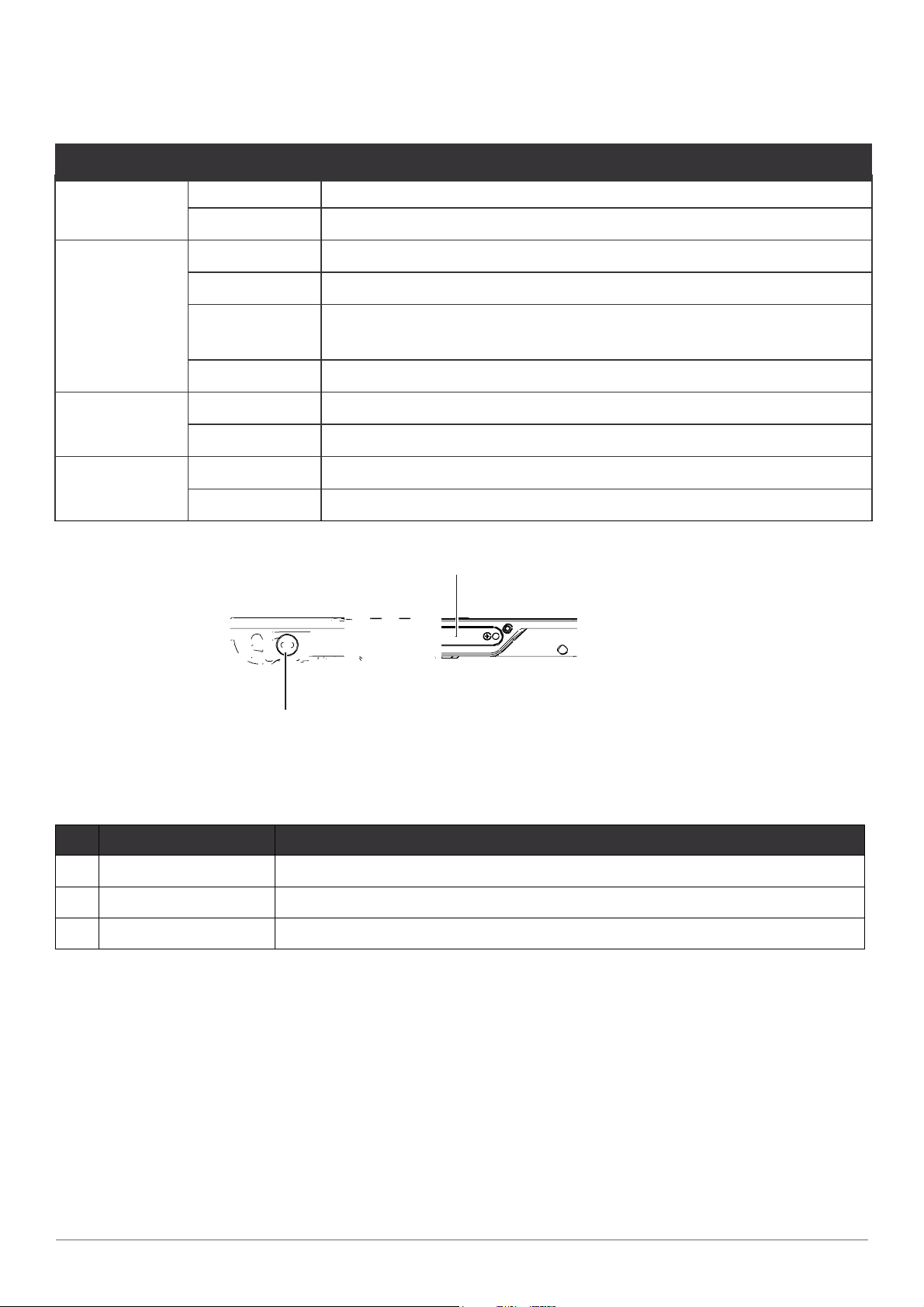
Bottom View
Table 5. Bottom View
Green: On Power on
Off Power off
Green: On Fully charged
Amber: On Charging
Amber:
Blinking
Off Not charging / no battery
Blue: On FN function switch on
Blue: Off FN function switch off
Blue: On Wi-Fi on
Blue: Off Wi-Fi off
Low power < 15%
1
2 3
Figure 3. Bottom View
No
1
Docking connector 30 pin connector for docking onto a station.
2
Kensington lock Lock the PA501 to a stationary object for security.
3
Pass-through Dual pass-through for WLAN, GNSS and WWAN.
12
Item Description

7. /
280 /
11
fn
f1 f2 fn
19
5 / 7.7
Dimensions
The following image lists the device dimensions without add-ons (mm/inches).
7
.
Front View ions
28 / 11
Introduction
23 / 0.9
2.3 / 0.9
Side View
13

Getting Started
Chapter 2. Getting Started
This section provides an outline of the steps necessary to setup a new PA501. A detailed
guide follows the listed items, see as follows.
For additional technical assistance, contact your RuggON representative. See “Contacting
RuggON” on page 30.
It is recommended to installing or remove accessorie
yourself and the device from electrostatic discharge, wear anti- static wrist straps or place the device on
an anti-static mat.
s on a clean, well-lit work surface. To protect
First Time Use
PA501 is under “Battery Ship Mode” and will not power on to preserve the battery and prevent
power loss. To enable “Regular Mode” and activate the battery, please connect the power
adapter to power on.
Charging the Battery
When you use the AC adapter to connect your PA501 to a power outlet, the standard and
external (optional) battery will automatically begin to recharge.
While the battery is charging, the power LED will be active. When the battery is fully charged, the
power LED is lit a solid green.
1.
Flip open the DC-IN cover to expose the DC-IN jack.
Opening the DC-IN Cover
14

2.
Connect the AC adapter to the DC-IN port.
Getting Started
Connecting the AC Adapter
After charging the battery, disconnect the AC adapte
1.
Insert one end of the cover first and angle the cover to seat it in place.
2.
Push in the cover to seal the DC-IN compartment.
Closing the DC-IN Cover
The DC-IN cover must be inserted correctly to prevent internal damage to the device.
Powering the Device On and Off
r and close the DC-IN cover.
Powering On the Device
Only power on the PA501 after connecting all of the peripherals and cabling.
1.
Press and hold the power button until the screen lights. The device runs through the start up
sequence and powers up.
Power On the PA501
15

■ Bot h Start screen and Desktop screen:
2. Tap
Power
>
Shut down
.
Getting Started
Powering Off the Device
■
Start screen:
Tap
■
Desktop screen:
1.
2.
1. Display charm bar and tap Settings.
> Shut down.
Tap and hold at the bottom left corner of the Desktop screen.
Tap Shut down or sign out > Shut down.
Installing the Micro SIM 2 Card
The device includes a micro SIM 2 card slot for cellular and wireless connection. Only a micro
SIM card is supported in the slot.
Check with your network or cellular service provider for availability and cost rates.
1.
Power off the PA501. See “Powering Off the Device” on page 19.
2.
Remove the service door and its screws.
Back View
Back View: Remove Service Door
16

fn
f1 f2
fn
Getting Started
3.
Take the micro SIM 2 card from its packaging.
4.
Push the SIM 2 card cover to open and place the micro SIM 2 card to the slot.
5.
Close the SIM 2 card cover.
F
Installing the Micro SIM Card
Removing the Protective Film from the Display
The front display of the PA501 is protected during transport by a transparent film. This film
should remain on the front display during assembly to avoid damage to the front display surface.
Only remove the film once all of the assembly work has been completed.
Removing the Protective Film
17

Operation
Chapter 3. Operation
Opening the I/O Compartment Cover
1.
Place the device display side down on a clean work surface.
2.
Locate the I/O compartment cover.
Left view
Right view
ON
OFF
Left I/O
SIM
SD
3.0
Right I/O
Compartment
Cover
Compartment
Cover
Side View: Locating the I/O Compartment Cover
3.
Unlock the latch. (Only available for the left I/O compartment cover)
Unlocking the Latch
4.
Pull out the I/O compartment cover.
Opening the I/O Compartment Cover
18

Closing the I/O Compartment Cover
1.
Place the device display side down on a clean work surface.
2.
Locate the I/O compartment cover.
Left view Right view
Left I/O
Compartment
Cover
ON
OFF
SIM
SD
3.0
DashON Utility
Right I/O
Compartment
Cover
Side View: Locating the I/O Compartment Cover
3.
Flip the I/O compartment cover and install.
Installing the I/O Compartment Cover
4.
Lock the latch. (Only available for the left I/O compartment cover)
Locking the Latch
The I/O compartment cover must be inserted correctly
to prevent internal damage to the device.
19

Operation
Connecting to External Cabling
To prevent damage to the device, connect all cabling and accessories before powering up the device.
Connect USB Cabling
The PA501 have one USB 3.1 Type C and two USB 2.0 Type A port for connecting USB
devices, such as a digital camera, scanner, printer, modem, and mouse. The USB Type A
port support USB 2.0 devices.
Connect Ethernet Cabling
The PA501 provides a Ethernet port for connecting Ethernet.
Use a shielded cable is required to maintain emissions and susceptibility compliance.
Connect LAN cable to Ethernet port on the PA501.
Connect Audio Cabling
For higher audio quality, you can send sound through external audio devices such as speakers,
headphones, or earphone using audio connector.
Connect RS-232 Cabling
Connect to RS-232 devices with an RS-232 cable.
1.
Open the right I/O compartment cover
2.
Align the RS-232 cable with the port in the device and connect it.
3.
Turn the locking screws on the cable to secure it to the device.
Handstrap, Carrying Handle and Shoulder Strap (Optional)
The PA501 can be optionally equipped with a handstrap, a carrying handle or a shoulder strap for
convenience and choice. Select the accessory that is right for your needs.
The handstrap can be installed with either the shoul
handle and shoulder strap can not be installed together due to space constraints.
der strap or the carrying handle. However, the
Connecting the Handstrap
20

1.
Remove the screws securing the bumpers.
Removing the Screws
2.
Install the D-rings.
DashON Utility
Make sure the D-rings are tightly secured before installing the handstrap.
Installing the D-rings
3.
Connect the handstrap on the D-rings.
When the handstrap is installed, the digitizer can be placed under the strap.
Connecting the Handstrap
21

Operation
Removing the Handstrap
1.
Unlock the handstrap from the D-rings.
Removing the Handstrap
2.
Remove the D-rings.
Removing the D-rings
3.
Secure the bumper and the PA501 with screws.
Securing the Screws
22

Connecting the Shoulder Strap
Connecting the Carrying Handle
DashON Utility
1. Attach the clips to the D-rings.
Removing the Carrying Handle
1.
Press in the clips to release them from the D-rings.
2.
Remove the clips.
Connecting the Carrying Handle
Removing the Carrying Handle
Connecting the Shoulder Strap
1. Attach the clips to the D-rings.
23

Removing the Shoulder Strap
Operation
Removing the Shoulder Strap
1.
Press in the clips to release them from the D-rings.
2.
Remove the clips.
1.
Installing the Standard Battery
The following instructions are for both standard and external batteries. The external battery is an
optional component. Only use components specifically designed for this device. Contact your local
representative for ordering information.
Make sure the power switch is switched to ON before installing the standard/external battery
1.
Place the device display side down on a clean work surface.
2.
Locate the battery.
Locking Switch
Release Button
Battery
24
Rear View: Locating the Battery

3.
Align the tabs on the battery with the slots on the chassis.
4.
Angle the battery in place and set the tabs in the chassis slots.
5.
Lower the raised end of the battery and press in place until an audible click is heard.
Installing the Battery
6.
Slide the locking switch on the top-left side to lock the battery.
DashON Utility
Locking the Battery
Make sure the latch is securely locked to prevent the battery from falling.
Removing the Standard Battery
1.
Place the device display side down on a clean work surface.
2.
Locate the battery.
Locking Switch
Release Button
Battery
Rear View: Locating the Battery
25

Operation
3.
4.
5.
Slide the locking switch on the top-left side to the unlock position.
Unlock the Battery
Press and hold the release button as shown in the image to release the battery.
Hold the battery and angle the left side up to remove.
Removing the Battery
Checking Battery Status
You can check battery status without turning on PA501. When PA501 is off, press “Barcode trigger”
key and the LED indicators will show the battery status as below:
Battery Status LED Indicator
Above 80% capacity Three indicators on
50% - 80% capacity Two indicators on
20% - 50% capacity One indicator on
Below 20% capacity One indicator blinking
26

DashON Utility
Connecting to a Wireless Network
Before you can make use of the PA501 wireless functions, you need to connect to a network.
The following is a set of procedures for connecting to a wireless network.
1.
Before beginning, make sure your Wi-Fi setting is enabled and you are within range of a
wireless network. If your Wi-Fi setting is disabled, proceed to step 2.
■
Look at the Network icon located at the right side of the taskbar. If the icon displays an
X in a red circle, you are not within range of a wireless network. Move to a different spot
until the Wi-Fi icon changes status indicating availability to a wireless network.
2.
From any screen, open the Charms bar by sliding your finger inward from the screen’s right
edge. The Charms bar displays along the screen’s right side.
3.
In the Charms bar, tap Settings to open the Settings menu.
4.
In Settings, tap the Network icon to display the Networks connection settings.
5.
The Wi-Fi menu displays. By default, the Wi-Fi menu is set to Off. Tap the bar next to Off to
toggle Wi-Fi to On. This enables the Wi-Fi option.
6.
Once W-Fi is enabled a listing of all available wireless networks displays. The wireless
networks with the strongest signal are atop the list.
7.
Select the network you want to connect to, and tap the Connect button. You can tap the
Connect Automatically check box if you connect to this network frequently. If you connect
to the network, you are finished with the process. The network is considered an Open
unsecured network, no password is required.
8.
If a password is required, type the password in the Enter the network security key
field. Alternatively, you can also push the WPS button on your router to begin the security
handshake.
9.
Tap Next to finish the connection process.
You have successfully connected to a wireless network.
27

30
Apps and Settings
Chapter 4. Apps and Settings
Desktop
Touch Panel Control
Do not allow the touchscreen to come into contact with other electrical devices. Electrostatic discharges
can cause the touchscreen malfunction.
To avoid damaging the touchscreen, do not tap it with anything sharp or apply excessive pressure to it with
your fingertip.
It is recommended not to use fixed graphics on part or all of the touchscreen for extended periods. Doing
so may result in afterimages (screen burn-in) or ghosting.
The device may not recognize touch inputs close to the edges of the screen, which are outside of the touch
input area.
It is recommended to use fingers when you use the touchscreen
Single tap
Single tap on the touch panel screen lets activate an application.

31
DashON Utility
Longer press tap
Long-pressing an application allows you to drag and drop the application or the application
shortcut to another desktop.
Long-pressing a desired file in the File Manager allows you to copy, cut, rename or delete the
selected file
Swiping
Swipe upwards, downwards, to the left, or to the right.
Spreading and pinching
Spread two fingers apart or pinch on the screen.
Input, insert, select or copy texts
The keyboard appears when you use word processor to edit documents or enter the web
address on the web browser address bar.
Check system information
View system specifications
There are two ways to view system specifications.
Swipe upward on desktop

30
Apps and Settings
1) Tap “DashON” App. Detail see “Chapter 5 RuggON DashON Utility”
2) Tap “Settings” to view and configure all of the system settings

31
Select “About tablet” to view the tablet information
DashON Utility
Shows the system specifications

30
Apps and Settings
Check the storage status
Select “Storage” to view the storage information
Shows the status of Storage

31
Check the system languages
Select “System” to view and configure system settings
While entry “System”, can tap Advanced to do more settings
DashON Utility
Select “Languages & Input”

30
Apps and Settings
Select “Languages” to configure the language settings
English (United Status) is the default
Tap “add a language” to choose and change languages

31
After adding a language, please long-pressing the bar and move it to the “1” position
DashON Utility
Check the date and time
Select “Date & time”

30
Apps and Settings
Make sure the “Date & time” is correct
Setting the Network, Internet and connected devices
Check the Network & Internet
Tap “Settings” and select “Network & Internet”
While entry “Network & Internet”, can tap Advanced to do more settings

31
DashON Utility
1) Turn on and select “Wi-Fi”
Select the name of your network and
Key in your password

30
Apps and Settings
2) Select “Mobile network” to check Networking settings
Make sure the SIM#1 card or SIM#2 card to be plugged in
Hot-swappable SIM #1 card design
Support Dual SIM Dual Standby (DSDS) for Data only
S
hows SIM#1 card information
Can tap Advanced to see more information

31
DashON Utility
Tap “card 2” to show SIM#2 card information
Can tap Advanced to see more information
Go back to the “Mobile network” and select “SIM cards” to decide which carrier you prefer

30
Apps and Settings
3) Select “Ethernet” to check Ethernet settings
Make sure RJ45 cable is plugged in
Turn on “Ethernet” to check Ethernet settings

31
DashON Utility
Hotspot & tethering
Select “Hotspot & tethering” to configure the device settings
Wi-Fi hotspot only supports 2.4GHz
C
onnection of a mobile device with other devices can be done over wireless LAN (Wi-Fi), over
Bluetooth or by USB

30
Apps and Settings
Connected devices
Select “Connected devices” to configure the device settings
Select “Pair” new device” to search the device
Should turn on wireless function

31
DashON Utility
Choose one of the available device names
Select “Connection preferences” to choose which devices you prefer to connect, like
Bluetooth, Barcode scanner or NFC…etc.

30
Apps and Settings
When 2D barcode is integrated in the system, and after turned on the function, there are three
modes can be selected
OCR is an optional feature
Apps & notifications
Select “Apps & notifications” to configure Apps settings

31
DashON Utility
View all apps and can set “Disable” or “Force stop” of them
Can tap Advanced to do more settings
Display
Select “Display” to configure display settings

30
Apps and Settings
Can adjust the configuration of Night light, Brightness, Wallpaper, Sleep mode, Auto-rotate,
Font size, Display size...etc.
Sound
Select “Sound” to configure volume settings for audio broadcasts

31
DashON Utility
Can set the configuration of Media volume, Call volume, Alarm volume, Notification
volume...etc.

30
Apps and Settings
Chapter 5. RuggON DashON Utility
Overview
The DashON resident program is designed to provide near-instant access to your device’s
settings and configuration within a single, easy to use interface.
The following information illustrates and describes the various settings available for
configuration through the DashON menus.
Important: Do not terminate or remove the DashON program manually or the ambient
light sensor and the function buttons will be malfunction.
Available functions are dependent on tablet model and operating system.
DashON Overview
Function Description
EXIT Minimize DashON and return to the desktop.
Info Viewer View system specifications. The menu is for display only.
Battery Shows the battery level or charging status.
SOH(External Battery) Shows the Health of external battery.
SOH(Backup Battery) Shows the Health of backup battery.
Button Setting Pre-defined functions settings. Supports function button
customizing.
Touch Setting Choose touch mode of finger, glove or stylus
Function Description

31
Button Lock
DashON Utility
Lock or unlock all the physical buttons except Power button.
Touch Screen Lock
Lock or unlock the touch screen.
Ignition Monitor Select turn-off time in seconds on vehicle docking
Pass-through Switch
Switch the usage of internal antenna or external antenna on
vehicle docking
Info Viewer
The Info Viewer displays the system’s hardware specifications.
Tap to display system information. The setting is for display purposes only
Info Viewer
Battery
Shows the battery level or charging status. The icon depends on your tablet.
SOH(External Battery)
Shows health status of the external battery. The icon depends on your tablet.
SOH(Backup Battery)
Shows health status of the backup battery. The icon depends on your tablet.

30
Apps and Settings
Battery & SOH
Button Setting
The physical function buttons are configured with pre-defined commands. However, the
buttons can be configured to open any number of executable commands. In combination
with the Fn key, the function buttons can trigger more commands.
Fn key depends on your tablet.
Barcode trigger button is not allowed for programming if 2D barcode reader is installed.
Button Setting
Select the function key to define and tap the drop-d
defined list of commands.
Alternatively, tap O
ther to select a specific executable file to attach to the function key.
own menu to choose from a pre-

31
DashON Utility
Additional shortcuts can be created by enabling the Fn + button. This allows the
creation of a second set of short cuts available by pressing Fn + Function Button.
Tap Default to restore each programmable button to the factory settings
Button Setting Menu
Name an App and save it to a designated file.

30
Apps and Settings
Touch Setting
Select a desired mode to begin operation
Touch Setting
Provide finger mode, glove mode and Stylus mode to b
e selected
T
ouch Setting Menu
Button Lock
The Button Lock function disables or enables the use of the physical buttons except Power
button. Tap to enable or disable the function.

31
DashON Utility
Button lock
Touch Lock
The Touch Lock function disables the touch functionality on the screen. Tap to enable the
function.
Button lock
Ignition Monitor
Ignition Monitor only works after the device is connected to RuggON Vehicle Dock(VD06)

30
Apps and Settings
Ignition Monitor
Select turn-on or turn-off time in seconds
Ignition Monitor
Pass-through Switch
This function is only available on the models with pass-through connector. This
function is only available when tablet is well connected to vehicle docking (VD06,
VD10), GPS, WWAN and Wi-Fi settings are available once the optional RF antenna
is connected.

31
DashON Utility
Passthrough Switch
The external antenna can be selected two from WWAN,
Wi-Fi or GPS.
Pass-through Switch Menu
Ext. 1: Wi-Fi and GPS are exclude.
Ext. 2: Wi-Fi and WWAN are exclude.
Ext. 1 Wi-Fi and Ext. 2 Wi-Fi are exclude.

30
Apps and Settings
The system may display an error when an incompatible external GPS antenna is
detected or setup is not completed after selecting GPS on Ext. 1.
Possible solutions for this issue are as follows:
Tap OK: The system reverts to the use of the built-in GPS antenna
At this time do not tap OK. See a possible solution as follows
Remove and re-connect the external antenna. If a connection is established, the error
no longer displays.
Remove the current external GPS antenna and replace it with a different one. If a
connection is established, the error no longer displays. The original GPS antenna may not be
compatible or is malfunctioning
GPS Failed
Display status delay is normal when detecting an ext
ernal GPS antenna.

31
DashON Utility
Chapter 6. Troubleshooting
Use the troubleshooting tables in this section to fix problems with the Wi-Fi connection, 802.1x
security, or general problems with operating the computer.
If you send the computer in for service, it is your responsibility to save the computer data and
configuration. RuggON is responsible only for ensuring that the hardware matches the original
configuration when repairing or replacing the computer.
Troubleshoot the Wi-Fi Connection
Use this troubleshooting table to help solve problems with your 802.11 radio connection.
Q. When you turn on the computer after it was suspended for a while (10 to 15 minutes or
longer), it can no longer send or receive messages over the network.
A. Host may have deactivated or lost current terminal emulation session. In a TCP/IP direct
connect network, turn off the “Keep Alive” message from host to maintain the TCP session
while the computer is suspended.
Q. The computer is connected to the network and you move to a new site to collect data. Your
computer now shows you are not connected to the network.
A. Move closer to an access point or to a different location to reestablish communications until
you reconnect with the network.
Q. The computer appears to be connected to the network, but you cannot establish a terminal
emulation session with the host computer.
A. There may be a problem with the host computer, or with the connection between the access
point and the host computer. Check with the network administrator to make sure the host is
running and allowing users to log in to the system.
Q. The computer appears to be connected to the network, but the host computer is not receiving
any information from the computer.
A. There may be a problem with the connection between the access point and the host
computer. Check with the network administrator or use your access point user’s manual.
Q. A network connection icon appears in the toolbar, but then disappears.
A. The computer may not be communicating with the intended access point. Make sure the
network name matches the access point network name.
The access point may not be communicating with the s
turned on, properly configured, and has 802.1x security enabled.
erver. Ensure the access point is

Apps and Settings
30
Troubleshoot Operating the Computer
Use this section to troubleshoot problems that may prevent you from being able to operate the
computer.
Troubleshooting
Q. You press the Power button and nothing happens.
A. Make sure that power is connected to the computer.
Q. The computer appears to be locked up and you cannot enter data.
A. Restart the computer.
Call Product Support
Simple instructions please contact the dealer, contact ruggon representative, or leave a message
visit the RuggON website at www.ruggon.com.
To better assist you have the following information
■
Configuration number
■
Serial number
■
Operating system, and MCU versions
■
Service pack version
■
System component versions
■
If you are using security, know the type and the full set of parameters
ready:


30
Maintenance
Chapter 7. Maintenance
Cleaning the Device
Danger to electric shock when cleaning or maintaining the PA501.
To avoid electric shock, turn the PA501 off and disconnect it from the power supply before cleaning or
maintaining it.
Housing
■
The housing of the PA501 is best cleaned with a damp cloth.
■
Use compressed air, a high-pressure cleaner or vacuum cleaner may damage the surface.
■
Use a high-pressure cleaner, the additional risk of water entering the PA501 may damage
the electronics or touch screen.
Touch Screen
■
Use neutral detergent or isopropyl alcohol on a clean soft cloth to clean the panel surface.
■
Prevent using any kind of chemical solvent, acidic or alkali solution.
Returning the Device
Please put the contents in the original package gently when you need to return the PA501.
Contacting RuggON
If you experience technical difficulties, please consult your distributor or contact the technical
services department:
www.ruggon.com

 Loading...