


MT7010
User’s Manual
v1.1

2
Contents
CONTENTS ..................................................................................................................................................................... 2
SAFETY PRECAUTIONS ........................................................................................................................................... 4
REGULATORY AND CERTIFICATION .................................................................................................................. 6
FCC ................................................................................................................................................................................................... 6
CE MARKING .................................................................................................................................................................................. 7
RADIO EQUIPMENT DIRECTIVE (2014/53/EU) .................................................................................................................. 7
LITHIUM BATTERY SAFETY STATEMENT ............................................................................................................................... 7
CHAPTER 1. PRODUCT INTRODUCTION .......................................................................................................... 8
HARDWARE SPECIFICATIONS ................................................................................................................................................... 8
OPERATING SYSTEM SUPPORT ..................................................................................................錯誤! 尚未定義書籤。
ENVIRONMENT ............................................................................................................................................................................... 9
I/O PORTS .................................................................................................................................................................................... 10
DIMENSION AND WEIGHT ........................................................................................................................................................ 11
MT7010 STANDARD .................................................................................................................................................................... 11
PACKAGE LIST ............................................................................................................................................................................ 12
CHAPTER 2. HARDWARE INSTALLATION ...................................................................................................... 13
INSTALLING/REMOVING THE SIM CARD ............................................................................................................................ 13
INTERNAL SIM SLOT (SIM2) .................................................................................................................................................... 13
EXTERNAL SIM SLOT (SIM1) .................................................................................................................................................. 15
CHAPTER 3. HARDWARE MOUNTING ............................................................................................................. 17
CHAPTER 4. START UP .......................................................................................................................................... 18
POWERING THE SYSTEM ........................................................................................................................................................ 18
CONNECTOR POWER .................................................................................................................................................................. 18
POWERING DOWN THE SYSTEM ............................................................................................................................................ 20
LED STATUS................................................................................................................................................................................ 21
ADJUST THE SPEAKER VOLUME .......................................................................................................................................... 22
AUTO-BRIGHTNESS ADJUSTMENT ...................................................................................................................................... 22
INTERNAL MICROPHONE ......................................................................................................................................................... 23
PROGRAMMABLE BUTTONS ................................................................................................................................................... 23

3
POWER MANAGEMENT……………………………………………………………………………………………………………..23
CHAPTER 5. JUMPERS AND CONNECTORS ................................................................................................ 24
BOTTOM VIEW ............................................................................................................................................................................... 24
EXTERNAL CONNECTORS PIN ASSIGNMENTS ................................................................................................................ 25
POWER CONNECTOR .................................................................................................................................................................. 25
RS-232 PORT (COM1) .............................................................................................................................................................. 26
USB AND RS-232/422/485 PORT (COM2)..................................................................................................................... 27
DIO AND CAN BUS PORT .......................................................................................................................................................... 28
CHAPTER 6. DASHON SETTING ......................................................................................................................... 29
DEVICE INFORMATION .............................................................................................................................................................. 30
VEHICLE STATUS ....................................................................................................................................................................... 31
COMMUNICATION SETTING .................................................................................................................................................... 32
ENABLE/ DISABLE MODULE ...................................................................................................................................................... 32
WWAN SETTING ........................................................................................................................................................................... 33
SYSTEM STATUS & SETTING ................................................................................................................................................. 34
POWER MANAGEMENT SETUP ................................................................................................................................................ 34
I/O CONFIGURATION .................................................................................................................................................................... 41
BRIGHTNESS SETTING ................................................................................................................................................................ 42
WATCHDOG TIMER ....................................................................................................................................................................... 42
PROGRAMMABLE BUTTON ........................................................................................................................................................ 45
LOCATION AND SENSOR .......................................................................................................................................................... 47
ENABLE/ DISABLE GPS RECEIVER ...................................................................................................................................... 48

4
Safety Precautions
1. Read these safety instructions carefully.
2. Keep this user’s manual for later reference.
3. Disconnect this equipment from any AC outlet before cleaning. Use a damp cloth. Do
not use liquid or spray detergents for cleaning.
4. For plug-in equipment, the power outlet socket must be located near the equipment and
must be easily accessible.
5. Keep this equipment away from humidity.
6. Put this equipment on a stable surface during installation. Dropping it or letting it fall
may cause damage.
7. Do not leave this equipment in either an unconditioned environment or in an above
40ºC storage temperature as this may damage the equipment.
8. The openings on the enclosure are for air convection to protect the equipment from
overheating. DO NOT COVER THE OPENINGS.
9. Make sure the voltage of the power source is correct before connecting the equipment
to the power outlet.
10. Place the power cord in a way so that people will not step on it. Do not place anything
on top of the power cord. Use a power cord that has been approved for use with the
product and that it matches the voltage and current marked on the product’s electrical
range label. The voltage and current rating of the cord must be greater than the voltage and current rating marked on the product.
11. All cautions and warnings on the equipment should be noted.
12. If the equipment is not used for a long time, disconnect it from the power source to avoid
damage by transient overvoltage.
13. Never pour any liquid into an opening. This may cause fire or electrical shock.
14. Never open the equipment. For safety reasons, the equipment should be opened only
by qualified service personnel.
15. If one of the following situations arise, get the equipment checked by service personnel:
a. The power cord or plug is damaged.
b. Liquid has penetrated into the equipment.
c. The equipment has been exposed to moisture.
d. The equipment does not work well, or you cannot get it to work according to the

5
user’s manual.
e. The equipment has been dropped and damaged.
f. The equipment has obvious signs of breakage.
16. Do not place heavy objects on the equipment.
17. The unit uses a three-wire ground cable which is equipped with a third pin to ground the
unit and prevent electric shock. Do not defeat the purpose of this pin. If your outlet does
not support this kind of plug, contact your electrician to replace your obsolete outlet.
18. CAUTION: DANGER OF EXPLOSION IF BATTERY IS INCORRECTLY RE- PLACED.
REPLACE ONLY WITH THE SAME OR EQUIVALENT TYPE REC- OMMENDED BY
THE MANUFACTURER. DISCARD USED BATTERIES ACCORDING TO THE
MANUFACTURER’S INSTRUCTIONS.
19. Continuously displaying a fixed pattern may induce image sticking. It’s recommended to
use screen saver or shuffle contents periodically when a fixed pattern is displayed on
the screen.

6
Regulatory and Certification
RF exposure warning
This equipment must be installed and operated in accordance with provided
instructions, and the antenna(s) used for this transmitter must be installed to
provide a separation distance of at least 20 cm from all persons and must not be
co-located or operated in conjunction with any other antenna or transmitter. End-users and
installers must be provided with antenna installation instructions and transmitter operating
conditions for satisfying RF exposure compliance.
FCC
This device complies with Part 15 of the FCC Rules. Operation is subject to the following two
conditions:
1. This device may not cause harmful interference.
2. This device must accept any interference received, including interference that may
cause undesired operation.
This equipment has been tested and found to comply with the limits for a Class B digital
device, pursuant to Part 15 of the FCC Rules. These limits are designed to provide
reasonable protection against harmful interference in a residential installation. This
equipment generates, uses, and can radiate radio frequency energy and, if not installed and
used in accordance with the instructions, may cause harmful interference to radio
communications. However, there is no guarantee that interference will not occur in a
particular installation. If this equipment does cause harmful interference to radio or television
reception, which can be determined by turning the equipment off and on, the user is
encouraged to try to correct the interference by one or more of the following measures:
Reorient or relocate the receiving antenna.
Increase the separation between the equipment and the receiver.
Connect the equipment into an outlet on a circuit different from that to which the
receiver is connected.
Consult the dealer or an experienced radio/TV technician for help.
Shielded interconnect cables and shielded AC power cable must be employed with this

7
equipment to insure compliance with the pertinent RF emission limits governing this
device. Changes or modifications not expressly approved by the system’s manufacturer
could void the user’s authority to operate the equipment.
Any changes or modifications not expressly approved by the party responsible
for compliance could void the user’s authority to operate the equipment.
This device is operable in 5.15 – 5.25GHz frequency range, then restricted in
indoor use only, Outdoor operations in the 5.15 – 5.25GHz is prohibitive.
.
CE Marking
This product has passed the CE test for environmental specifications when shielded cables
are used for external wiring. We recommend the use of shielded cables. Please contact your
local representative for ordering information.
This product has passed the CE test for environmental specifications. Test conditions for
passing included the equipment being operated within an industrial enclosure. In order to
protect the product from being damaged by ESD (Electrostatic Discharge) and EMI leakage,
we strongly recommend the use of CE-compliant industrial enclosure products.
Radio Equipment Directive (2014/53/EU)
This device complies with the essential requirements of the Radio Equipment Directive
(2014/53/EU).
Lithium Battery Safety Statement
Lithium battery inside. Danger of explosion if battery is incorrectly replaced. Replace only
with the same or equivalent type recommended by battery manufacturer.
THIS PRODUCT CONTAINS LITHIUM-ION BATTERY PACKS. IT MUST BE
DISPOSED OF PROPERLY. CONTACT LOCAL ENVIRONMENTAL AGENCIES
FOR INFORMATION ON RECYCLING AND DISPOSAL PLANS IN YOUR AREA.

8
Chapter 1. Product Introduction
Item
Description
Processor
Qualcomm MSM8909 (Quad-Core Cortex-A7 1.1/1.3 GHz)
Memory
LPDDR2 RAM 1GB/2GB
Storage
eMMC 8GB/16GB
One MicroSD slot
Display
7 inch TFT LCD
500 nits
Viewing angel: 145(H)/ 160(V) (CR>10)
Touch Panel
Projected Capacitive Touch Screen
Wireless
Connectivity
802.11 a/b/g/n 2x2
Bluetooth V4.1
GPS / GLONASS
4G LTE / HSPA+ / GPRS
Item
Description
Power Input
9-36VDC,3.5A
Battery
1950mAh, 3.6V
Housing
(Mechanical)
PC+ABS, fanless design
Certification
CE, FCC, CB
MT7010 is an in-vehicle terminal with 7” high resolution display and 500nits brightness, and
is flexible to support a wide range of wireless connection capability. The device is well-suited
for fleet management, asset management, EOBR and ELDs application.
It is compliant to ISO 7637-2, SAE J1455 and SAE J1113 and its optimized power system is
designed for cold cranking, load dump, transient voltage and ESD.
The device is engineered with IP65 protection rating, a wide temperature design, wide input
range, and rich expanding interfaces that support in-vehicle connectivity.
Hardware Specifications

9
Environment
Operating temperature:
-20°C (-4°F) to 60°C (140°F)
In accordance with MIL-STD-810G CHANGE1 Method 501.6 High Temperature
Procedure II - Operation
In accordance with MIL-STD-810G CHANGE1 Method 502.6 Low Temperature
Procedure II – Operation
Storage temperature:
-30°C (-22°F) to 70 °C (158°F)
In accordance with MIL-STD-810G CHANGE1 Method 501.6 High Temperature
Procedure I – Storage
In accordance with MIL-STD-810G CHANGE1 Method 502.6 Low Temperature
Procedure I - Storage
Relative humidity:5% to 95% @ 30°C (86°F) to 60°C (140°F) non-condensing in
accordance with MIL-STD-810G CHANGE1 Method 507.6 Humidity Procedure II
Aggravated Cycles (Fig 507.6-7)
Vibration Test:
Operating: MIL-STD-810G CHANGE1 Method 514.7 Category 4,
Fig 514.7C-2 Common carrier (US highway truck vibration exposure);
Fig 514.7C-3 Composite two-wheeled trailer;
Fig 514.7C-4 Composite wheeled vehicle
Non-Operating: MIL-STD-810G CHANGE1 Method 514.7 Category 24, Fig
514.7E-1 (General minimum integrity exposure)
Shock Test:
Operation: MIL-STD-810G CHANGE1 Method 516.7 Procedure 1 Functional
Shock
Non-Operation: MIL-STD-810G CHANGE1 Method 516.7 Procedure V Crash
Hazard Shock

10
I/O Ports
Item
Description
Serial
1 x RS-232 (COM1), with 5V/600mA (max.) or 12V/300mA (max.)
1 x RS-232/422/485, non-isolation (COM2)
USB*
1 x USB 2.0 for host A-type connector (500mA)
1 x USB 2.0 via DB15 connector
*only one USB storage is functional simultaneously
Ethernet
10/100Base-T (RJ45) x 1
Digital I/O
2 x DI ; 2 x DO
Digital Input: DI 0~30V
Digital Output:
(1) circuit design reserved for 2 x DO 5V
(2) default setting 2 x DO: OC output, High level depends on external
pull up resistor, Up to 30 VDC maximum sink 50 mA per channel
CAN
CAN bus (SAE J1939)
Audio
1 x Headset for Mic-in/ Audio out
2 x Internal Mic-in
Speaker
Built-in dual 2W speaker
11
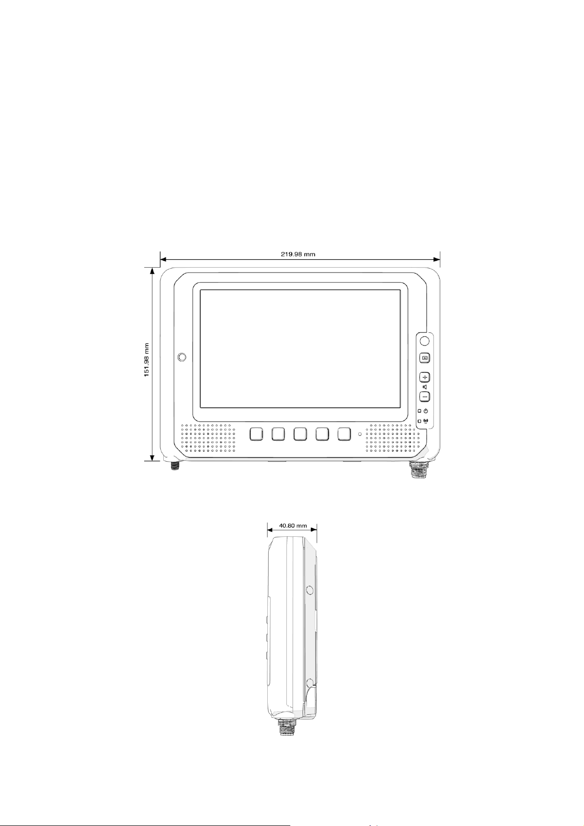
Dimension and Weight
MT7010 Standard
Dimension: 219.98 x 151.98 x 40.8mm / 8.66 x 5.98 x 1.60in. (W x H x D)
Weight: 1.25 kg/ 2.76 lbs.
Front View Dimension
Side View Dimension

12
Package List
Before you begin the installation or configuration process, make sure to inspect all the
components and accessories. Contact your representative if there are any missing or
damaged items.
Please verify the delivery of the contents upon receipt
MT7010 in-vehicle terminal
Bare wire power cable with circular power connector
2-feet DB15 male connector cable with multiple end
2-feed DB15 male connector cable (no termination)
5-meter external GPS antenna
NOTE: The packaging material has been selected to optimally protect your device. After
unpacking, store the original packaging material in the event that you need to return for
shipment.

13
Chapter 2. Hardware Installation
This chapter provides information for the installation and removal of SIM card.
Installing/Removing the SIM card
The device provides dual micro SIM slots for cellular and wireless connection. One is inside
(SIM2) and the other is accessible from external SIM cover (SIM1).
You can either Install SIM card in internal or external SIM slot and this selection can be done
via SIM slot assignment in DashON. The factory default is the external SIM slot (SIM1).
Please see the following guidelines to install or remove the SIM card.
Please make sure that the device is completely powered off and make
sure the power status LED light is off when installing/removing the
internal SIM card.
Internal SIM slot (SIM2)
1. Shut down the system properly and disconnect the device from all power sources.
2. Un-mount the device from the mounting apparatus; make sure that the display surface is
protected.
3. Remove the screws securing the cover and remove it.

14
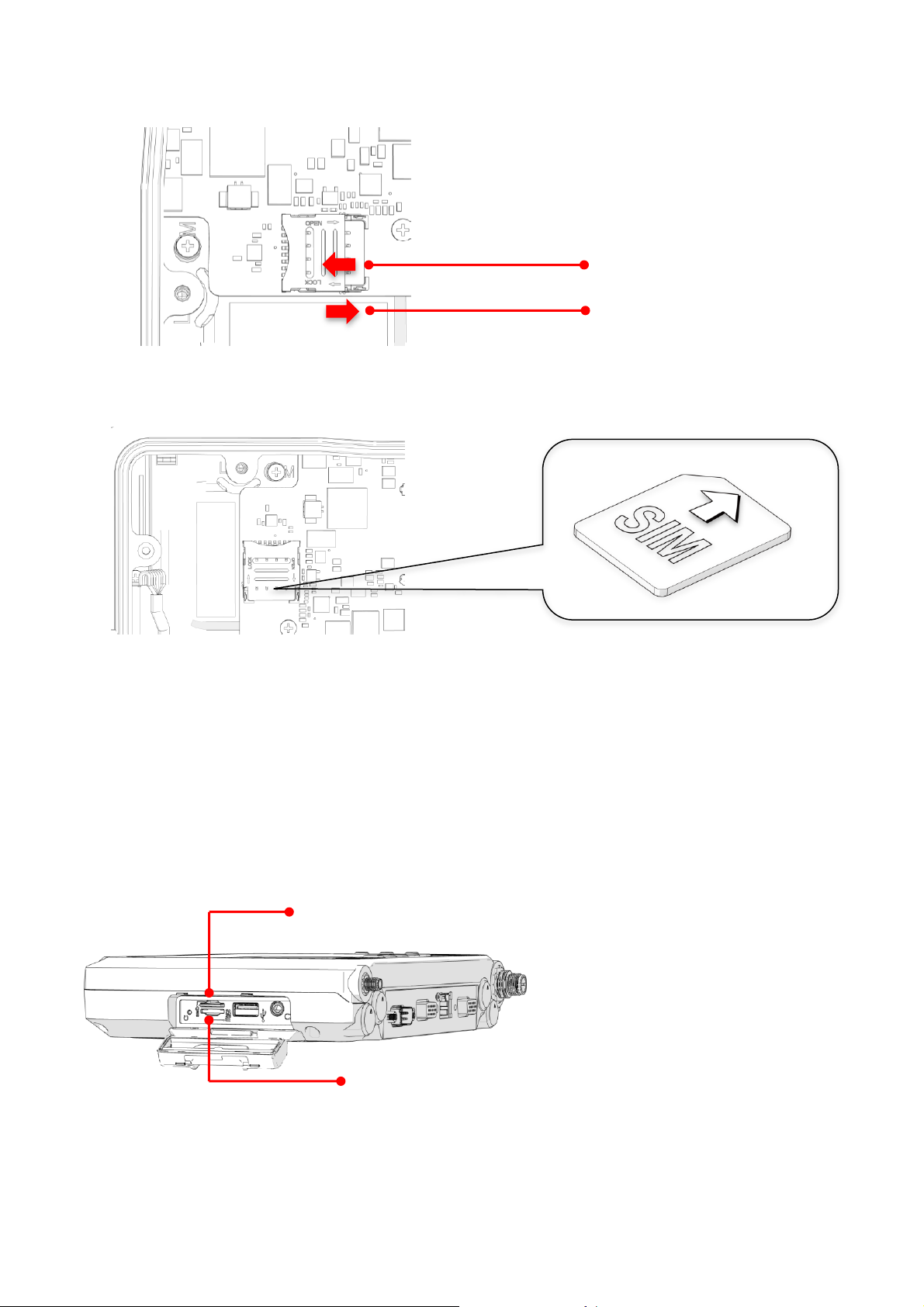
4. Once the service cover is removed, you can see the Micro SIM card slot.
5. To release the SIM card holder, slightly lift the front edge of the cover on the card holder
and slide it backwards. Open the cover.
15
SIM Card Slot
SD Card Slot
To open the SIM card holder
To lock the SIM card holder
6. Turn your SIM card to the angled corner of your SIM card to match the angled corner of
the SIM card holder.
7. Insert the SIM card into the SIM card holder.
8. Close the cover of the SIM card holder.
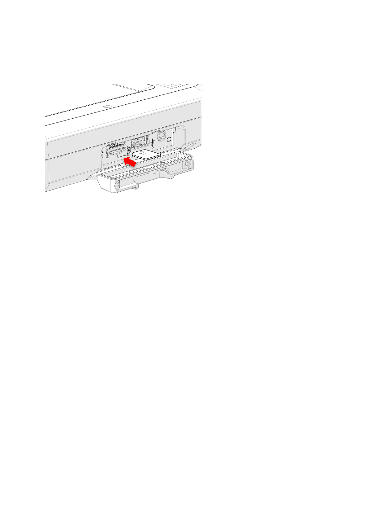
External SIM slot (SIM1)
1. Shut down the system properly and disconnect the device from all power sources.
2. Open the side cover; you can see the Micro SIM card and SD card slot.
16
3. Insert your SIM card. Make sure the angled corner of the card is positioned correctly.

17
Chapter 3. Hardware Mounting
The MT7010 supports a standard VESA version MIS-D, 75, C (75mm distance quadrate
order, M5 thread, deepness 6mm) through the four drill holes on the back side of the device.
Notes: To prevent any damage or injury, make sure the mounting bracket is securely
attached.

18
Chapter 4. Start up
Wire Color
Description
RED
V+
BLACK
V-
GREEN
Chassis Ground
WHITE
ACC/ Ignition
Powering the System
Connector Power
MT7010 allows a wide range of DC power input from 9~36V via a 5-pin M12 A-code power
cord. There are two options to start up the MT7010 via car power cable or external power
adapter.
The wire definition.

19
Top of the arrow mark
Power source from car power cable
1. The bare wire lead cable allows you to directly wire 12 V or 24 V car power supply.
Please follow the wire definition to connect to your power source.
2. Plug the power code into the power connector on the top of the arrow mark.
3. Twist the nut to lock the power connector to the device.
4. MT7010 will turn on automatically when the power supply is connected to the device.

20
Power source from external power adapter
If your power source is from external power adapter, it means the power source isn’t
controlled by AAC/Ignition signal. Please short red (V+) and white (ACC/ Ignition) wires.
Make sure that all the power supplies are disconnected when you plug the
power cord into the power connector.
Powering Down the System
MT7010 will be auto power off in one minute when the power supply is removed.
21
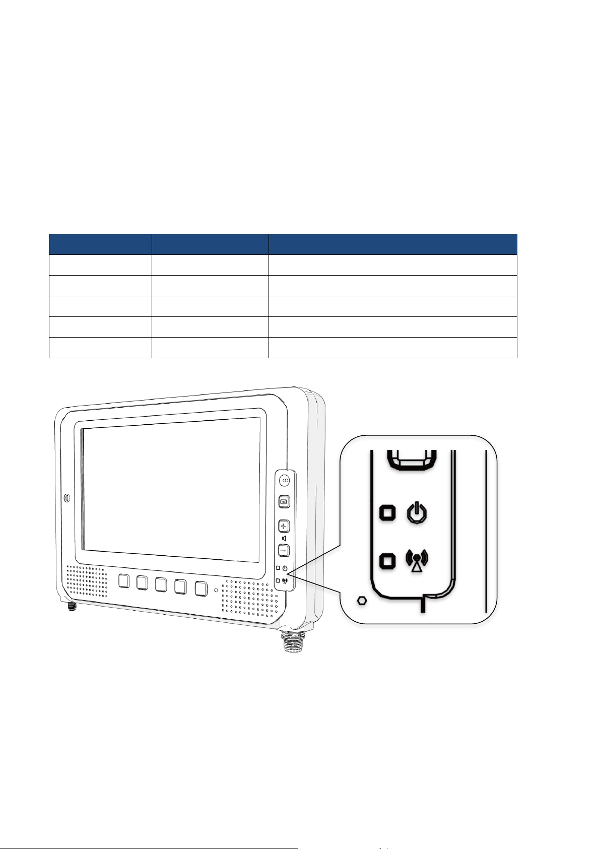
LED
Status
Description
PWR
Blink Green
Power up
PWR.
Blink Yellow
Load BIOS/ boot loader
PWR
Solid Green
System ready for use
PWR
Blink Red
Abnormal vehicle battery
Comm.
Solid Green
WWAN enabled
LED Status
The LEDs on MT7010 are status indicators that show the operating status of your system.
The status indicators can help pinpoint possible failed hardware components causing
specific symptoms. There are two status indicators in the front panel. Refer to the
description below.

22
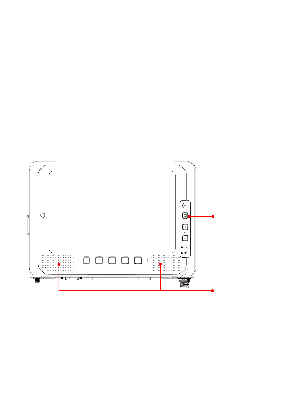
Adjust the Speaker Volume
Volume Control
Ambient light sensor
MT7010 provides the volume control buttons to adjust the speakers’ volume; you can also
control the overall level of sound using Windows. When you press the top part of the volume
button, it makes the volume louder; pressing the bottom part makes the volume lower
Press the button to increase the volume.
Press the button to decrease the volume.
Auto-Brightness Adjustment
When you use MT7010, you may well encounter different lighting conditions that make it
difficult to see the information on screen. MT7010’s built-in the ambient light sensor on the
front panel supports auto-dimming, which you can also disable to manually adjust the
screen’s brightness; this setting can be done via DashON.
23
System on/off
Internal MIC-in
Internal Microphone
MT7010 is equipped with two internal microphones, so you don’t need an external one. In
addition to the built-in speaker and microphones, you can plug external headsets in the
audio jack.
Programmable Buttons
MT7010 provides default commands for five programmable buttons. You can configure the
programmable buttons via DashON to different commands or keyboard shortcuts to better fit
your work style.
Power Management
In additional to settings in Windows Control Panel, MT7010 also provides DashON for
configuration setting which includes power management and system setup. Please refer to
Chapter 6 for configuration setting in DashON.

24
Chapter 5. Jumpers and Connectors
Power Input Connector
GPS Antenna Connector (SMA Jack)
RS-232 with PWR
(COM1)
LAN
DIO, CAN bus
RS-232/422/485, (USB 2.0
conversion) (COM2)
Bottom View

25
Pin
Signal
1
DC+
2
N/A
3
GND
4
N/A
5
ACC/ Ignition
1
2
3 4 5
External Connectors Pin Assignments
Use this section as a reference for the pin assignments of the various ports available on the
MT7010.
Power Connector
Note: Please refer to section 1 in Chapter 4 for connecting the external power cable to power
source.

26
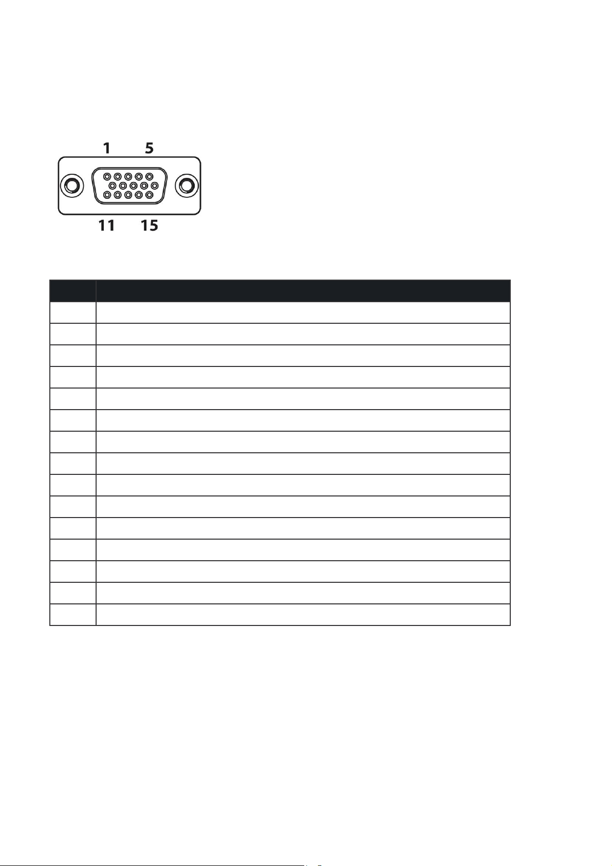
RS-232 Port (COM1)
Pin
Signal
Description
1
DCD
Data carrier detect (input)
2
RXD
Receive data (input)
3
TXD
Transmit data (output)
4
DTR
Data terminal ready (output)
5
GND
Signal/power ground
6
DSR
Data set ready (input)
7
RTS
Request to send (output)
8
CTS
Clear to send (input)
9
RI / PWR
Bar code scanner power (5V/600mA & 12V/300mA max) or Ring
indicator (input)

27
Pin
Signal
1
RS-422 TX+
2
RS-422 RX+
3
RS-485 TX+
4
RS-232 TX
5
GND
6
RS-422 TX-
7
RS-422 RX-
8
RS-485 TX-
9
USB 5V
10
RS-232 RX
11
GND
12
USB DP
13
USB DM
14
USB 5V
15
NC
USB and RS-232/422/485 Port (COM2)
We provide Y-cable with DB15 male connector which is the RS232/422/485 and USB
converter. Please contact your local representative for ordering information
28
DIO and CAN bus Port
Pin
Signal
1
CAN_H
2
N/A
3
N/A
4
FWD
5
WHEELTICK
6
CAN_L
7
N/A
8
N/A
9
CARD POWER
10
GND
11
N/A
12
DIO_OUT1 (5V 10mA)
13
DIO_IN1 (5V 100mA)
14
DIO_IN2 (5V 100mA)
15
DIO_OUT2 (5V 10mA)
We provide the DB15 male connector to multiple pins without termination cable. Please
contact your local representative for ordering information

29
Chapter 6. DashON Setting
You can use DashON to configure the device for your demo or test. We also provide the
corresponding SDK for your application development. DashON will is auto-run in
background while the system turns on. This section is to brief you on what functions are
included in DashON and how to set up based on Windows OS.
1. Device Information
It provides information of system hardware, software, and firmware version.
2. Vehicle Status
This section is to demo how to read the vehicle information such as vehicle battery
voltage, fuel, speed and so on while connecting with vehicle SAE J1939. We use the
simulator to run the demo.
3. Communication Setting
This is to enable / disable Wi-Fi/BT/WWAN and configure the related setting.
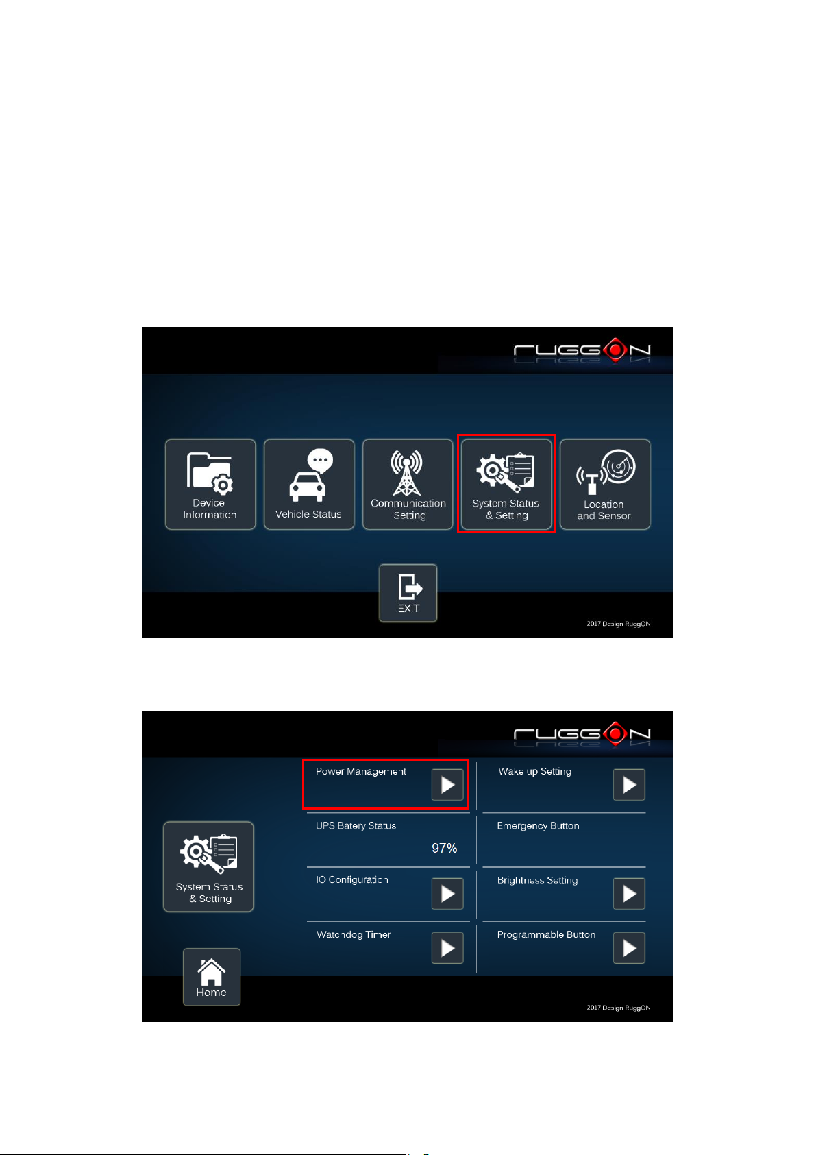
4. System Status & Setting
This section contains the major configuration of the system device. Power management,
wake up event, IO configuration, brightness and watchdog timer setting are included.
5. Location & Sensor
GPS configuration setting and temperature status
Click on the DashON icon if DashON is not running in background

30
Device Information
Click on the “Device Information” icon
In device information, you can see the PCBA version, DashON utility version and system
model name.

31
Vehicle Status
Vehicle status shows some vehicle information from the simulator.
The related AT command is available upon request. Please contact local sales
representatives or login to the support website.

32
Communication Setting
1 2
Communication setting allows you to enable/ disable Wi-Fi/WWAN/Bluetooth via DashON
utility. Please click on the “Communication Setting”
Enable/ Disable Module
Item 1. Click on the switch bar to Enable/ Disable Wi-Fi function.
Item 2. Click on the switch bar to Enable/ Disable Bluetooth function

33
WWAN Setting
If WWAN module is present in the device, you can click on “WWAN setting” to get into the
detailed setting.
You can set the two major features including WWAN RF on/off and SIM slot selection.
1. Module RF Enable/ Disable: to enable or disable the WWAN RF transmission. A
message will then pop up.
2. SIM slot assignment: This feature is only available for the device with multiple SIM slots.
34
System Status & Setting
This section is to set and read the system status. It covers power management, internal
backup battery, IO configuration, wake up event and so on.
Power Management Setup
Please click on the “Power Management”
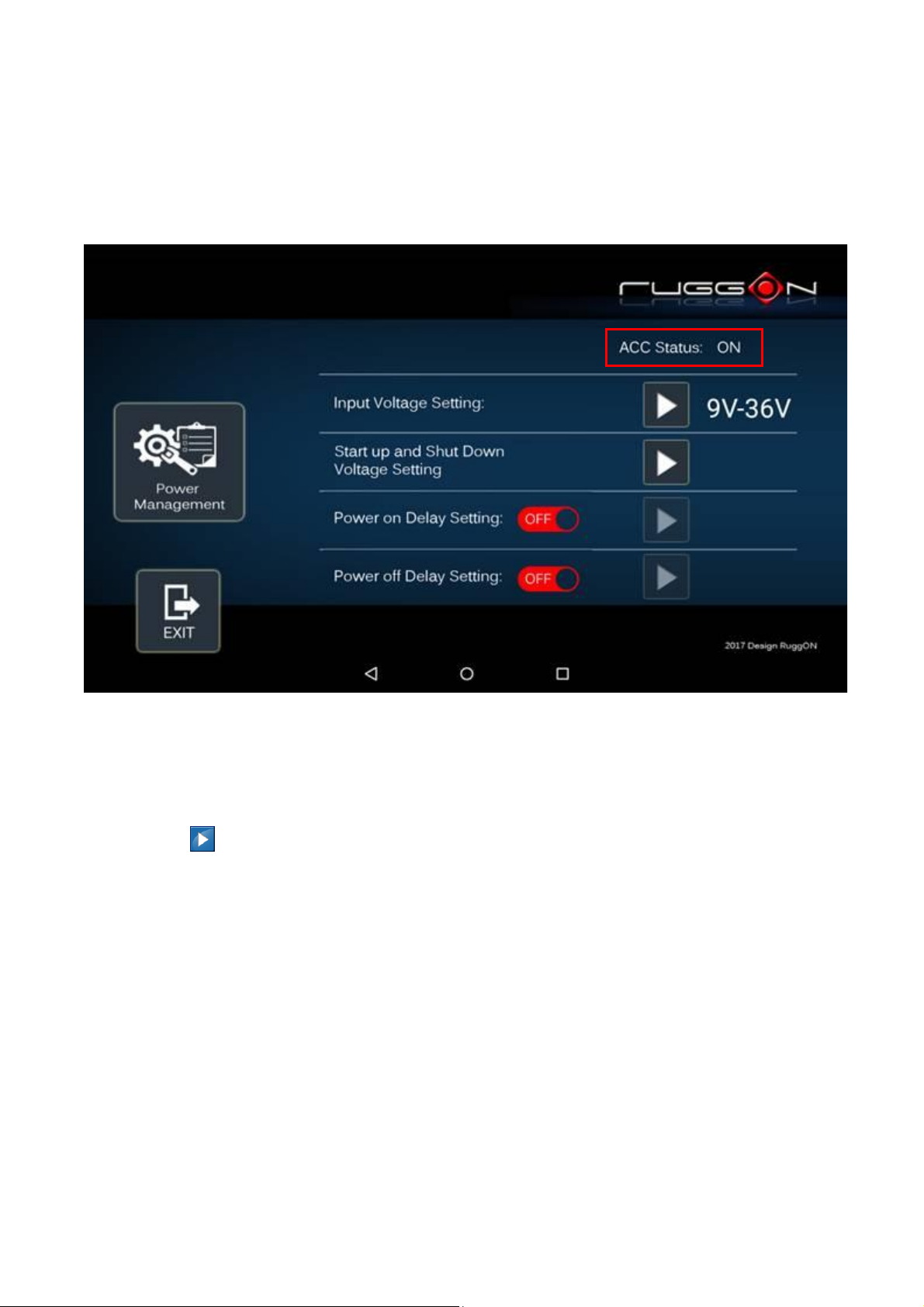
35
ACC Detection Setting
In MT7010 design setting, it supports ACC sense. You can check its status from ACC status.
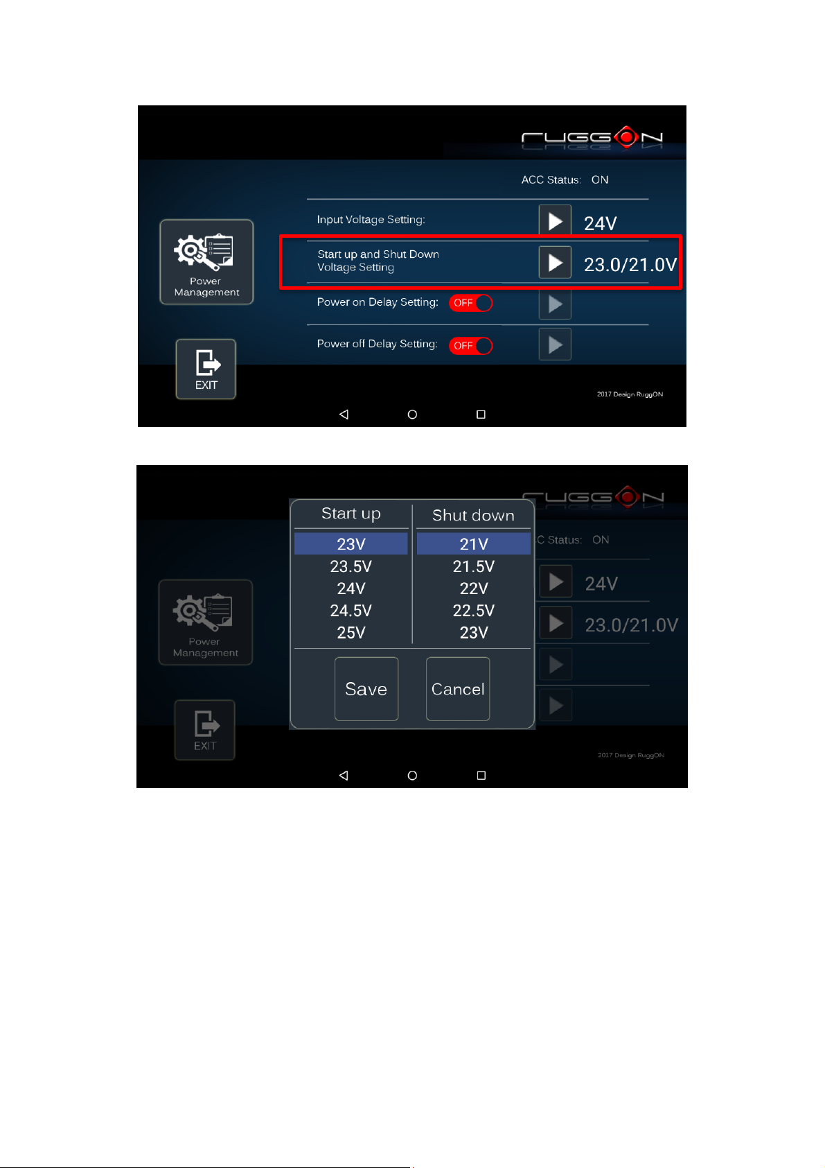
Input Voltage Setting
Click on the to the input voltage selection.
You can select the power input voltage either 9~36V or 12V or 24V. If 9~36V is selected, it
means the system can be powered on while the voltage ranges from 9~36V.
Please note if you use a 19V power adapter, the input voltage must be selected to 9~36V.

36
If 12V or 24V is selected, you can also select the startup and shut down voltage setting.

37 38
If the above selection items do not meet your demand, please contact local sales
representatives.

39
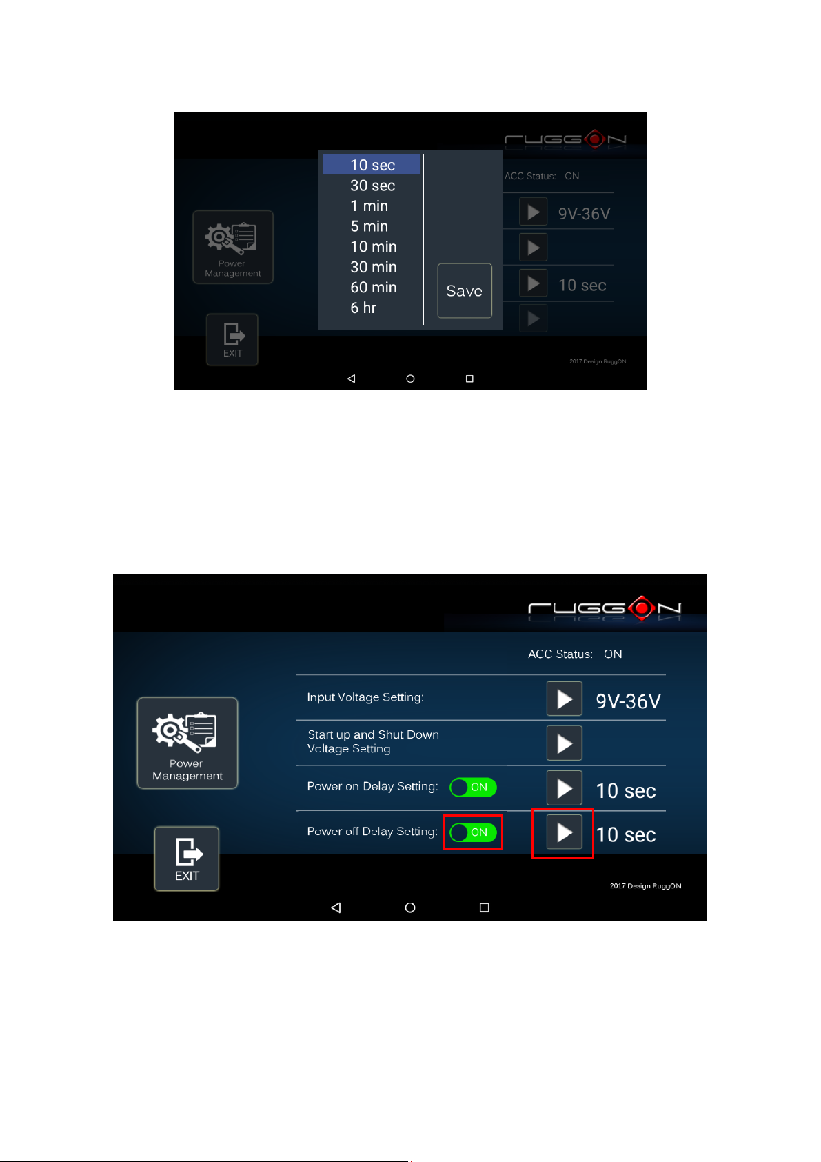
Power On/Off Delay Setting
Power on delay function enables you to power on the device after the ACC is on for a
specified period of time. Enabled power off delay function lets the device remain on until the
ACC is off for a specified period of time.
Power On Delay
Switch the to , click on the , and you will see the selection list.
Delay time can be set at 10sec/30sec/1min/5min/10min/30min/60min/6hr
40
Power Off Delay
Same as power on delay setting process; you can also set the power off delay.
Delay time can be set at 10sec/30sec/1min/5min/10min/15min/30min/60min/6hr

41
I/O Configuration
COM1 Setting
RS232 (COM1) supports 5V or 12V power output for users to easily connect with barcode
scanner or other equipment. The maximum current is up to 5V/600mA & 12V/300mA.
If you don’t need the power output, just select 0V output to avoid the equipment damage.
Please note if system power source is from backup battery (no DC input available), COM1
will stop supplying the power output.

42
COM2 Setting
The COM2 includes RS-232, RS-422 and RS-485 signals. Please select your required item
and connect the Y-cable converter to the system. Please refer to the pin out description for
correct connection.
Brightness Setting
Brightness adjustment is to optimize the operation of the backlight LEDs under a variety of
daylight conditions. MT7010 supports auto-dimming and manually adjusts the brightness.
If auto-dimming is enabled, the brightness is auto adjusted along with the changes of
environmental light. You can also manually change the display brightness via programmable
buttons or the bar adjustment in DashON. For programmable button setting, please see
“Programmable Button “section. MT7010’s display brightness is set to automatic adjustment.
You can also turn off “Auto-Dimming” and drag the scroll bar to adjust display brightness.
Watchdog Timer
This section is about the timer setting of watchdog and the simulation of watchdog functions.
When the system is hanging due to some reasons, you are able to reboot the system
automatically after the set time frame.

43
Double click on the DashON icon, and then click on the 4th icon “System Status & Setting”.
Click on the “Watchdog Timer”

44
Select the timer setting.
Turn on the watchdog switch.
If you’d like to test if watchdog timer is enabled and working, please click on the “simulation”
icon. The “simulation” is to simulate the system on hang and reboot it after the set time
frame.
45
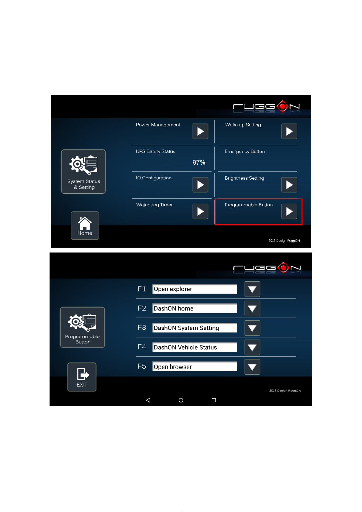
Programmable Button
Programmable buttons can be set to different functions per user’s definition.
46
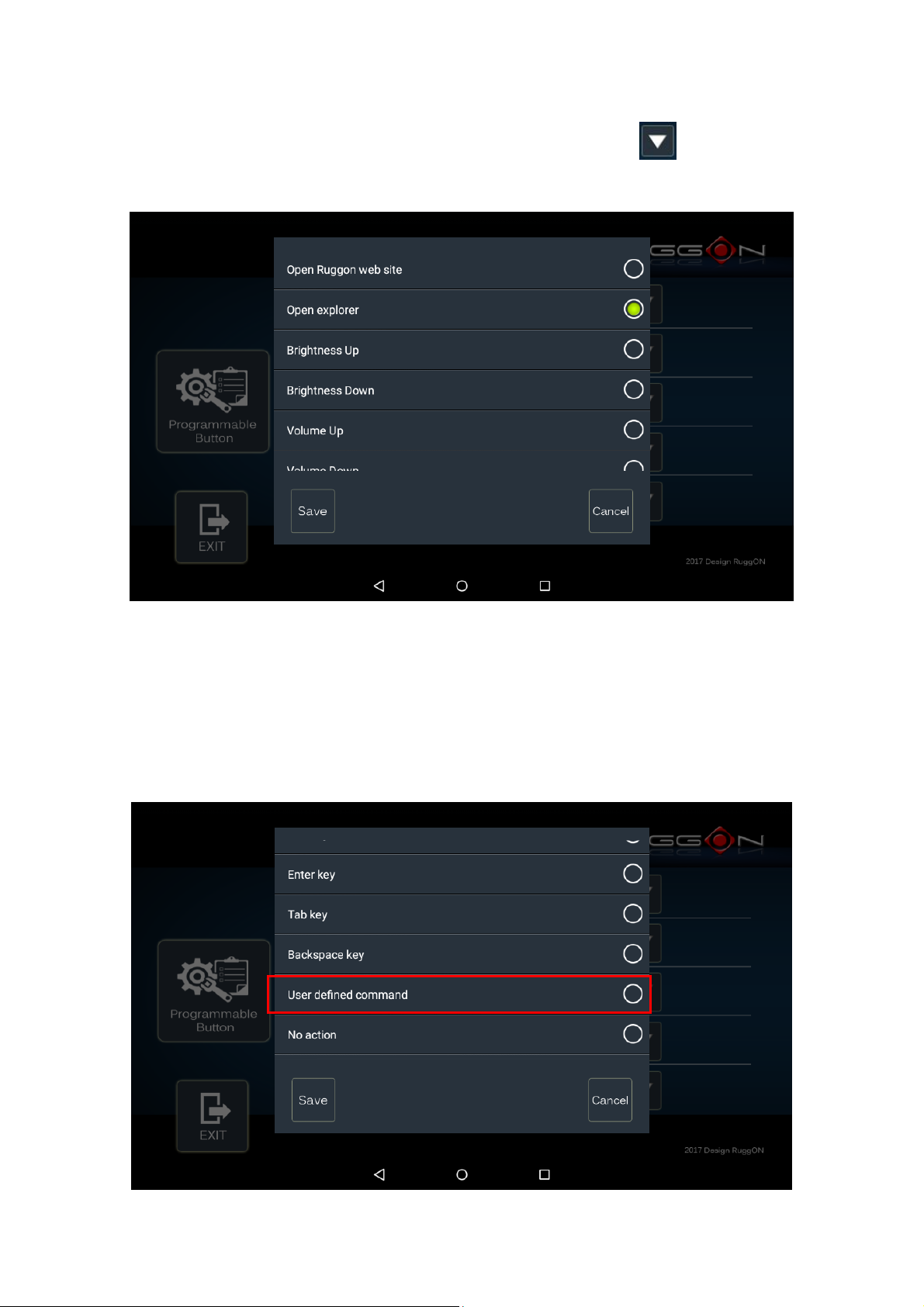
Select which function key button you want to set and then click the to select the
function from the list.
User can also define the keystrokes for function keys by selecting the “User Defined
Command” from the list.

47
Location and Sensor
MT7010 provides the GPS receiver and G-Sensor built-in. DashON provides both setting
and information and also links to the Google map locations for demo applications.
You can also use the general freeware GPS viewer to set GPS setting.
Click on the “Location and Sensor”
Module RF: to enable or disable the GPS receiving function.
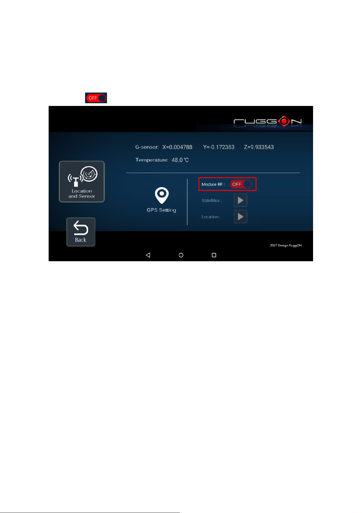
48
Enable/ Disable GPS Receiver
The default GPS receiver is enabled in MT7010. If you want to disable the receiver, switch
“Module RF” to .
 Loading...