

Page 1
1
Panel PC
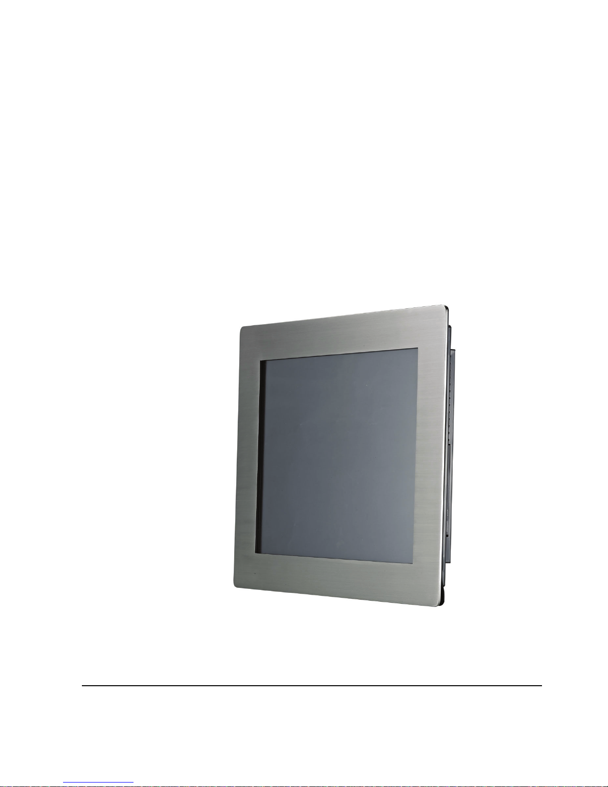
RI-1902 19” Panel PC
User’s Guide
Version: A1.0
Users guide Ver. A1.0
Nov, 2013
Page 2

RI-1902 User’s Guide
2
Notice
Copyright
The copyright of this user’s guide belongs to any authorized company
and is protected by copyright law. This means partial or full duplication
of this document
(electronically, mechanically or otherwise) is prohibited
without the permission of the authorized company.
The contents may be modified without notice for the improvement of
design, function, and reliability.
We do not guarantee the prevention of data loss. Please be cautious
not to lose important data and keep back-ups at all times.
Even though we did our best in drawing up this user’s guide, there
may be omissions and errors we failed to notice. Manufacturers and
suppliers cannot be held liable for problems stemming from those
errors and omissions.
Registered Trademark
Windows 7, XP Pro Embedded is a registered trademark of Microsoft.
Intel ATOM are registered trademarks of Intel.
Company names and product names mentioned in this document are
used to help your understanding and are registered trademarks.
The permissible level (Class A) of electromagnetic waves
The product was tested for electromagnetic waves and was rated as
class A, certified for sale and use worldwide.
Page 3

Notice
3
Caution
For safe and proper installation and use of this product, please read
this guide carefully.
Even though this product is equipped with a safety device to prevent
users from getting injured, please follow the instructions carefully.
Caution during installation
z Install on an even and stable place to prevent product damage
and injury.
z Install in a place with good ventilation to reduce humidity and to
prevent overheating.
z Keep objects with magnetic properties away from this product.
z Check the operational voltage before plugging the power cord
into the outlet.
z Use the power cord that is included with the product and do not
place heavy things on it.
z To prevent electric shock and fire, do not use an outlet that is
damaged or that is not standard.
z If you plug the power cord into an extension cord, be sure that
the total voltage of all the devices connected to the cord does
not exceed the number specified on it.
Caution during use
z If peripheral equipment is connected to this product, turn on the
power source of the peripheral equipment first when you starting
up. On the contrary, when shutting down, turn off the power
source of this product first to prevent damage to the product.
z Please make sure that no liquid enters into the product. This can
cause damage to the product, fire, or electric shock.
Page 4

RI-1902 User’s Guide
4
z Unplug the power cord before cleaning this product. Please
wipe with tissues or fabrics that are sprayed with a PC cleaner
and do not directly spray the product.
z When this product will be idle for an extended period of time,
unplug the power cord to prevent damage stemming from power
surges.
z When unplugging the power cord, pull by the plug, not the wire.
z Do not place this product in a place where the temperature is
over 60
o
C (140oF) and ventilation is poor. This may damage the
product.
z The optimum temperature for the operation of this product is
40
o
C, so keep electric heaters away from this product.
z Take precautions to avoid losing data stored on the hard disc of
this PC and back-up important data at all times in case of an
unforeseen accident.
z Do not attempt to disassemble this product. When this PC
needs repairs or updates, request warranty service and have a
service person do the work.
z Should the following situations occur, contact one of our quality
assurance divisions.
9 When liquid gets into the product or when it is exposed to
humidity for an extended time
9 When this PC does not operate well even though you are
following the instructions
9 When this product has fallen and broken or become cracked
during delivery.
Page 5

Table of Contents
5
Table of Contents
Notice ............................................................................................... 2
Copyright.....................................................................................................................................................2
Registered Trademark ................................................................................................................................2
The permissible level (Class A) of electromagnetic waves ........................................................................2
Caution........................................................................................................................................................3
Caution during installation .....................................................................................................................3
Caution during use.................................................................................................................................3
Table of Contents .............................................................................. 5
Chapter 1 Introducing the PANEL PC............................................... 6
Product features..........................................................................................................................................6
Unpacking ...................................................................................................................................................7
Optional devices..........................................................................................................................................7
Other peripherals ........................................................................................................................................8
Preparing you PANEL PC...........................................................................................................................9
Connect the AC Power Adapter.............................................................................................................9
Turn ON the PANEL PC ......................................................................................................................10
Chapter 2. Knowing the Parts ........................................................... 11
Dimension .................................................................................................................................................11
Cut-Out Dimension ...................................................................................................................................12
Panel mount Kit Installation ......................................................................................................................13
Front and Rear sides : ..............................................................................................................................15
Right Sides :..............................................................................................................................................17
Left Sides : ................................................................................................................................................18
Rear Sides : ..............................................................................................................................................19
Chapter 3. Starting the computer for the first time............................ 20
For Windows 7 ..........................................................................................................................................20
Step 0: Windows 7 and basic driver pre-setup .................................................................................20
Step 1: To set up the computer.........................................................................................................21
Step 2: The installation of drivers for other peripherals ....................................................................23
Step 3: The installation of software for other peripherals..................................................................23
Step 4: Completion of setup..............................................................................................................23
Chapter 4. System Upgrades ............................................................. 24
System upgrades ......................................................................................................................................24
Hardware upgrades .............................................................................................................................24
Software upgrades...............................................................................................................................24
Chapter 5. Reinstalling the OS ......................................................... 25
How to reinstalling Windows 7 ..................................................................................................................25
Appendix 1. Troubleshooting ........................................................... 27
Appendix 2. Product specifications................................................... 30
Appendix 3. Product warranty .......................................................... 33
Appendix 4. Jumper Setting.............................................................. 35
Page 6

RI-1902 User’s Guide
6
Chapter 1 Introducing the PANEL PC
Product features
The panel computer combines a CPU board, LCD display, and userfriendly touch screen within a slick, compact chassis.
Each product is a compact, highly integrated, network-ready computer
with the fullest I/O connectivity.
Even though the PANEL PC is very compact, its functionality is
limitless. It supports out-dated and conventional peripheral devices,
adapting to users’ working environments. It also supports the latest
peripheral devices with its four built-in USB ports (compatible with
USB v2.0).
The PC enables wireless networking without additional equipment
using its built-in network adaptor.
The PC’s 19” TFT-PANEL display, directly driven by digital signals,
offers a clearer image than that of separate TFT-PANEL monitor of the
same class, which is driven by analog signals. Furthermore, it allows
for the use of extended screens and has multi monitor functionality
because it is equipped with an extension port for connecting to TVs or
other external monitors.
This PC is designed to run best using Windows 7, XP Embedded,
Microsoft’s operating system. When used with the Windows 7, XP
Embedded operating system, you can get a more stable and diverse
computing environment.
The adoption of a 1 9 ” TFT-PANEL monitor minimizes harmful
electromagnetic waves and power consumption. Its design is
engineered for the human body to minimize eyestrain.
Page 7

Chapter 1 : Introducing the Panel PC
7
A1.0
Unpacking
This product is packaged with cardboard paper for safe delivery. If
there is a defect or missing part, contact the agency where you
purchased the product.
The box should contain the following items.
9 19” PANEL PC main body
9 60W AC/DC power adapter
9 AC power cord
9 Panel mount clips x16 & screws
9 Waterproof silicone pad (Installed)
9 Fix frame
9 Users Guide (This document)
9 Master CD (with the driver file for backup)
Optional devices
9 Wireless LAN Mini PCI-E card & Antenna
(built in the main body)
A touch screen is optional and you can order it before the product is
shipped. To enable touch screen, you need to have the following
device; Please carefully the touch screen if you assembly system
by yourself.
9 19” Touch Screen
[For reference]
This PC has a Mini PCI-E slot in its main body allowing for expandability
with peripheral devices that have a Mini PCI-E card. Our company will
launch new models can support wireless LAN.
Page 8

RI-1902 User’s Guide
8
Other peripherals
This PC supports the following peripheral devices
9 Printer
9 Six serial communication port (COM1~6)
9 USB devices (compatible with USB 2.0)
9 External speakers/headphones
9 External microphones
9 External audio devices
9 External monitors
[For reference]
z What is USB?
USB is a high-speed serial bus standard for the connection of peripheral
devices that reduces the use of valuable system resources. Devices
that support USB are USB mice, USB keyboards, USB PC cameras,
USB HDD, and USB memory sticks.
Page 9
Chapter 1 : Introducing the Panel PC
9
A1.0
Preparing you PANEL PC
These are only quick instructions for using you PANEL PC.
Read the later pages for detailed information on using your PANEL PC
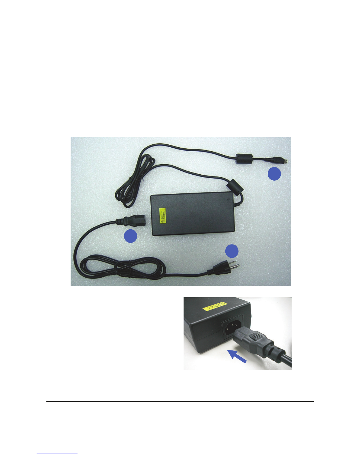
Connect the AC Power Adapter
1. Insert power cord into power adapter
1
3
2
Page 10
RI-1902 User’s Guide
10
2.
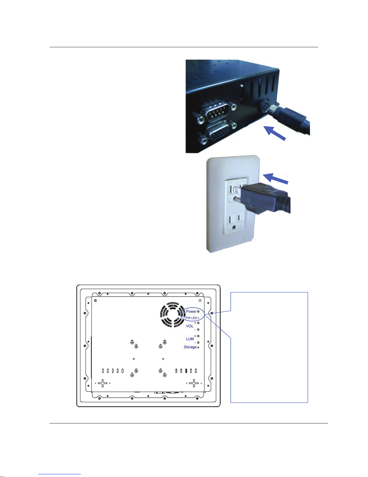
Insert power adapter cable into
“Power Input” of rear I/O panel
3. Insert power cord into outlet
Turn ON the PANEL PC
1. Before turn on power
button the PW LED
is Red color.
2. Press the power
Button and release.
( In Windows OS, this
button can also be used to
safely turn OFF the
Panel PC. )
3. PW LED become
Green color.
Page 11
Chapter 2 : Knowing the Parts
11
Chapter 2. Knowing the Parts
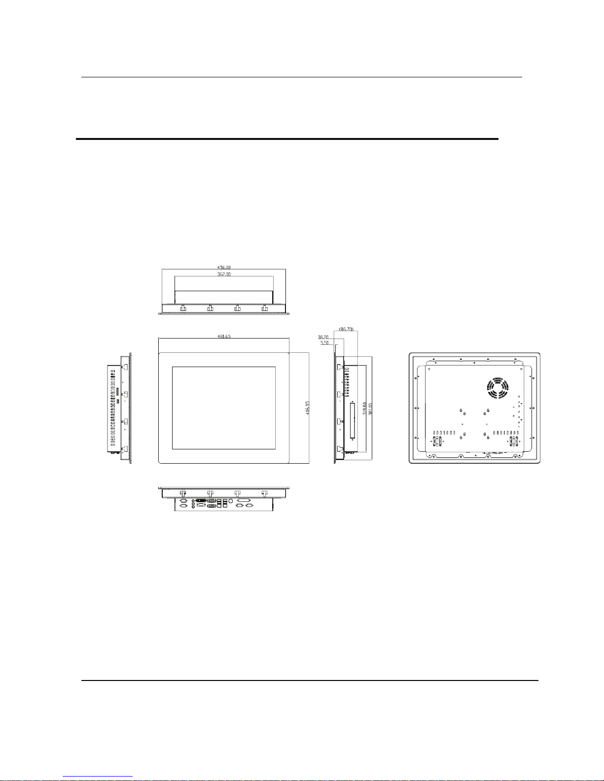
Dimension
Unit : mm
Page 12
RI-1902 User’s Guide
12
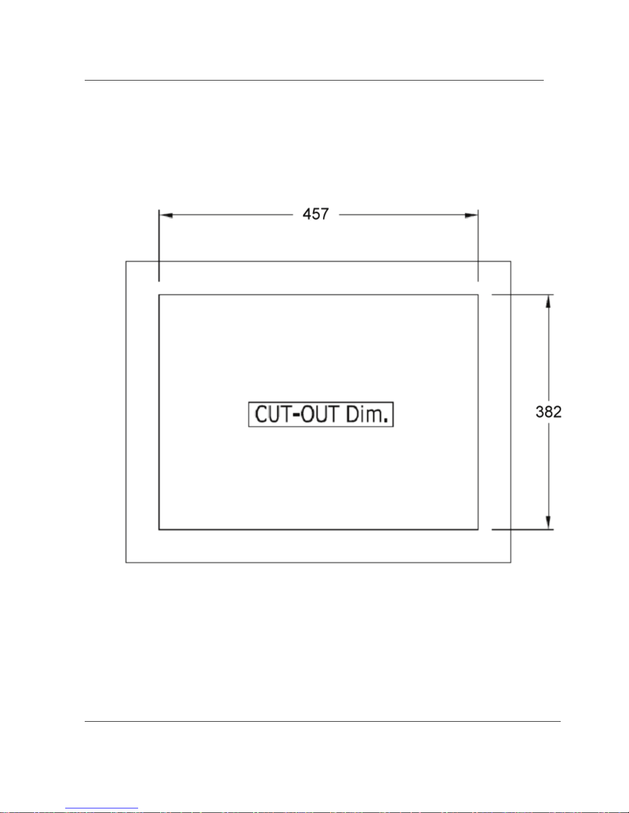
Cut-Out Dimension
Unit : mm
Page 13
Chapter 2 : Knowing the Parts
13
A1.0
Panel mount Kit Installation
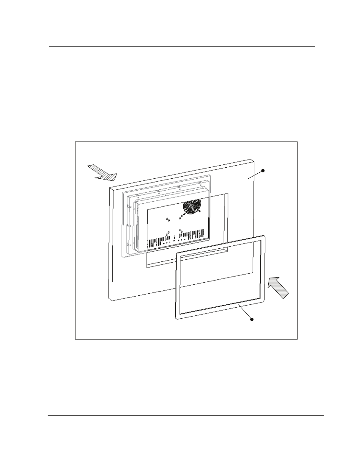
Some screw sets will come with the product for user to mount the
monitor on the wall. See the steps below along with the illustration.
Step 0: Locate panel pc and fix frame set on the wall.
Fix Frame
Wall
Page 14
RI-1902 User’s Guide
14
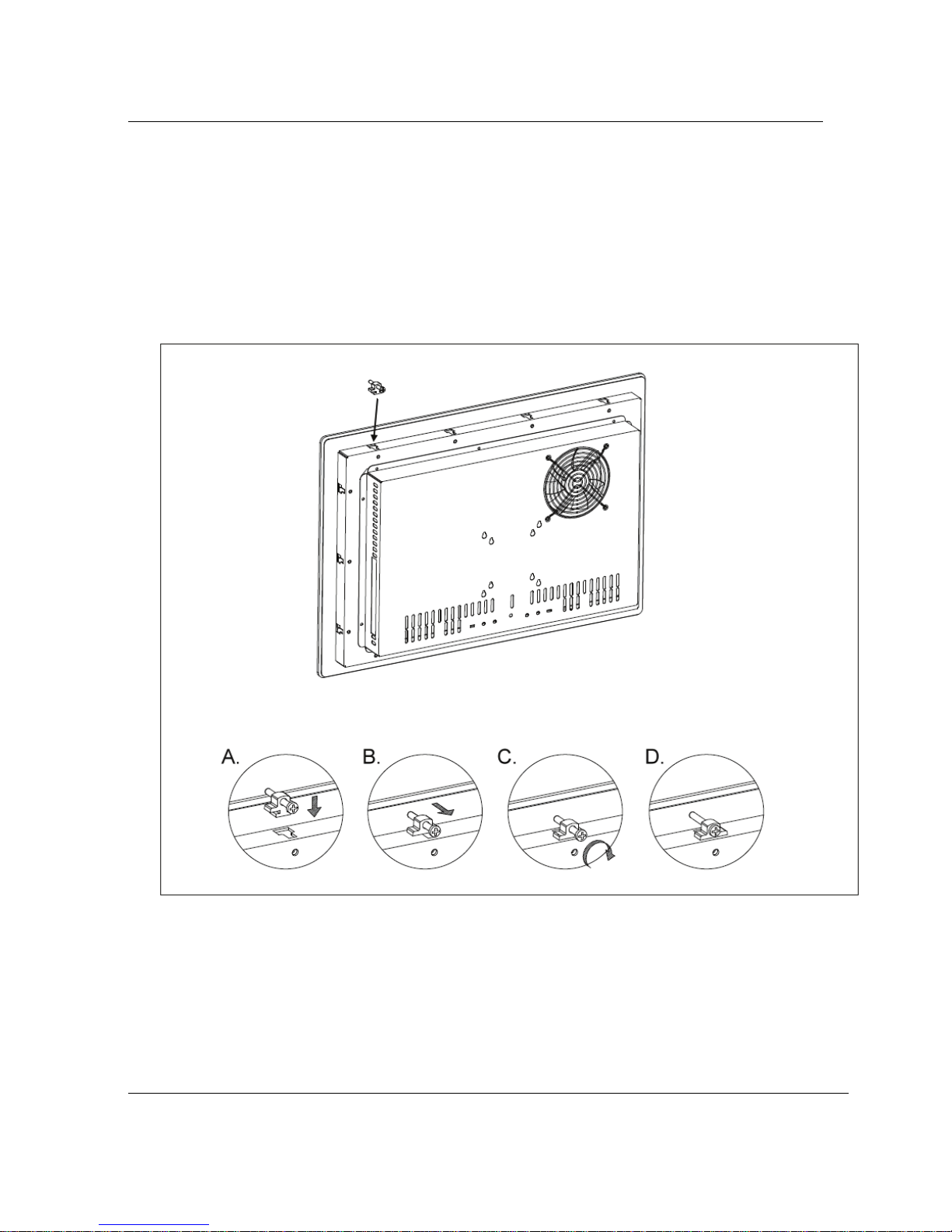
Step 1: Bore the screw into the screw hole.
Step 2: Locate the screw set into the hole around the panel pc as the
illustration and pull it back to lock the screw set on the hole. (A. B,)
Step 3: Turn the screw around to make it tight until it is closed to the wall. (C.)
Step 4: Lock the panel pc to the wall with the screw set. (D.)
.
Panel Mounting
Page 15
Chapter 2 : Knowing the Parts
15
A1.0
Front and Rear sides :
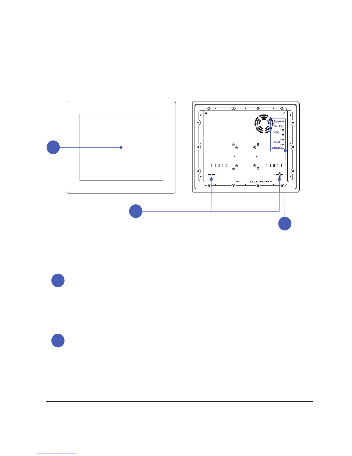
Display Panel
The display panel functions the same as a desktop monitor.
The PANEL PC uses an active matrix TFT LCD, which provides excellent viewing like
that of desktop monitors. Unlike desktop monitors, the LCD panel does not produce any
radiation or flickering, so it is easier on the eyes. Use a soft cloth without chemical
liquids (use plain water if necessary) to clean the display panel.
Pixels H x V : 1280 x 1024.
Audio Speaker System
The built-in stereo speaker system allows you to hear audio without additional
attachments. The multimedia sound system features an integrated digital audio controller
that produces rich, vibrant sound (results improved with external stereo headphones or
speakers). Audio features are software controlled.
1
2
3
1
2
Page 16
RI-1902 User’s Guide
16
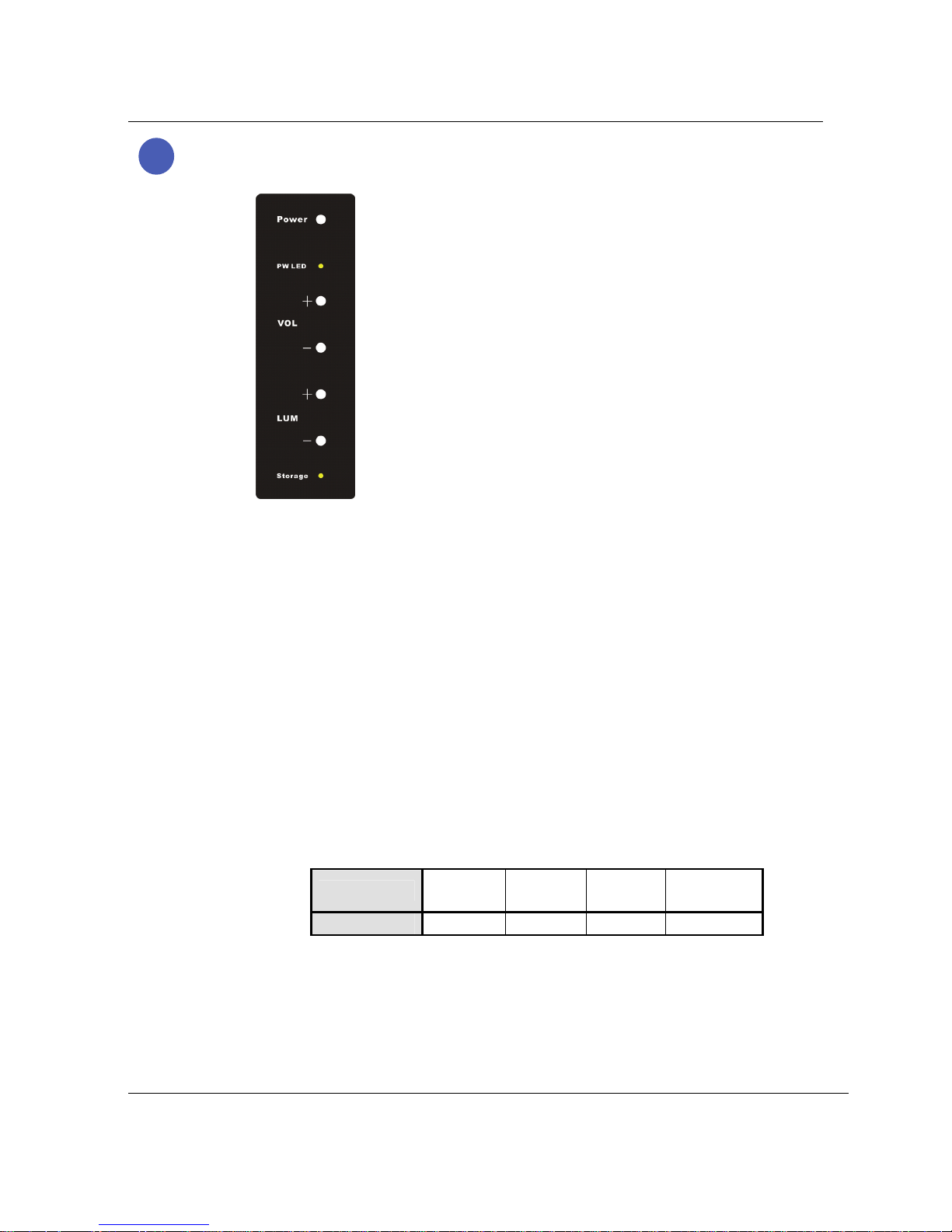
Instant Keys and Status Indicators
z Power button
Power : Turns the computer on and off.
z Buttons for adjusting the speaker volume
VOL : Up(+)/Down(-) :
Adjusts the sound volume of the internal speaker.
z Buttons for adjusting the screen luminance
LUM : Up(+)/Down(-) :
Adjusts the luminance of the TFT-LCD display.
z Status indicator lights
PW LED : Indicates power status.
Power status
Working
(G0/S0)
Sleeping
(S1~S4)
Soft Off
(G2/S5)
Mechanical
Off (G3)
LED Color Green Red Red Red
Storage LED : Indicates the hard disc is working,
LED Color : Green.
3
Page 17
Chapter 2 : Knowing the Parts
17
A1.0
Right Sides :
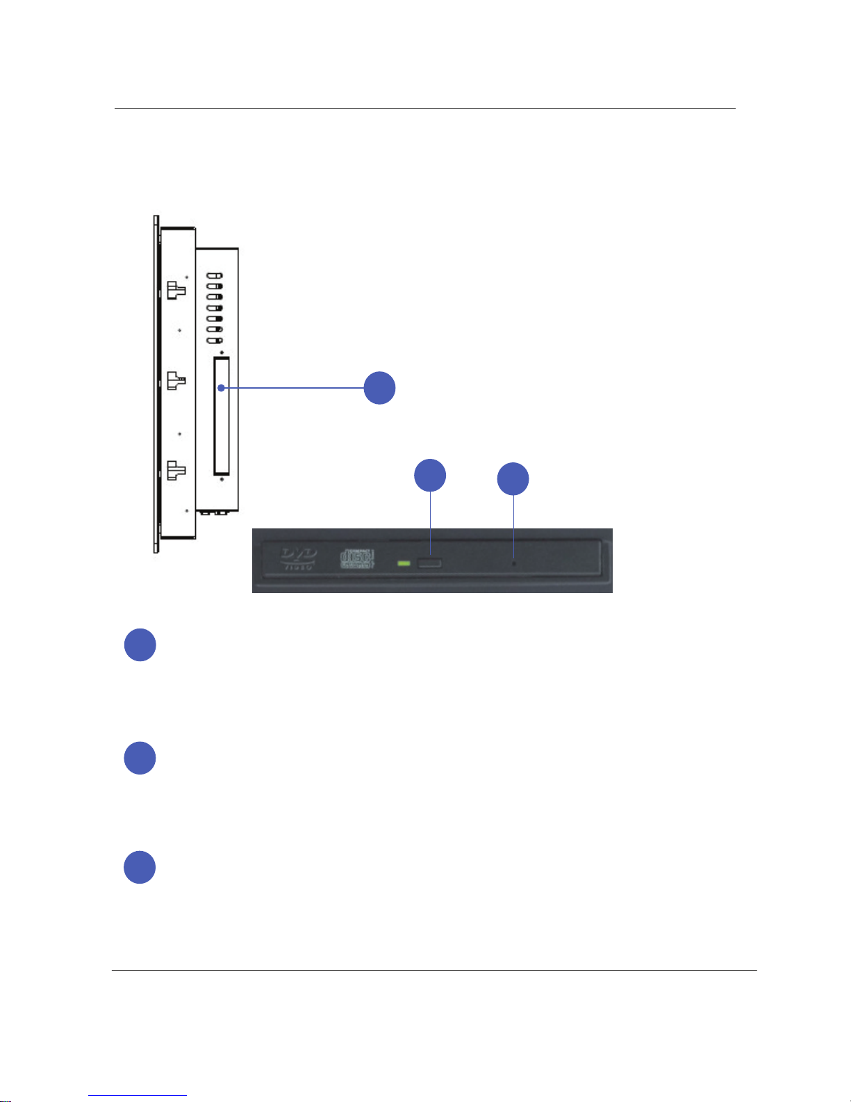
Optical Drive
The PANEL PC comes in various models with different optical drives.
The PANEL PC optical drive support Slim COMBO and Slim DVD Multi (RW)
capabilities. See the marketing specifications for details on each model.
Optical Drive Electronic Eject
The optical drive eject has an electronic eject button for opening the tray.
You can also eject the optical drive tray through any software player or
by right clicking the optical drive in Windows™ “My Computer”
Optical Drive Emergency Eject (location varies by model)
The emergency eject is used to eject the optical drive tray in case the electronic eject
does not work. Do not use the emergency eject in place of the electronic eject.
1
1
2
3
2
3
Page 18
RI-1902 User’s Guide
18
Left Sides :
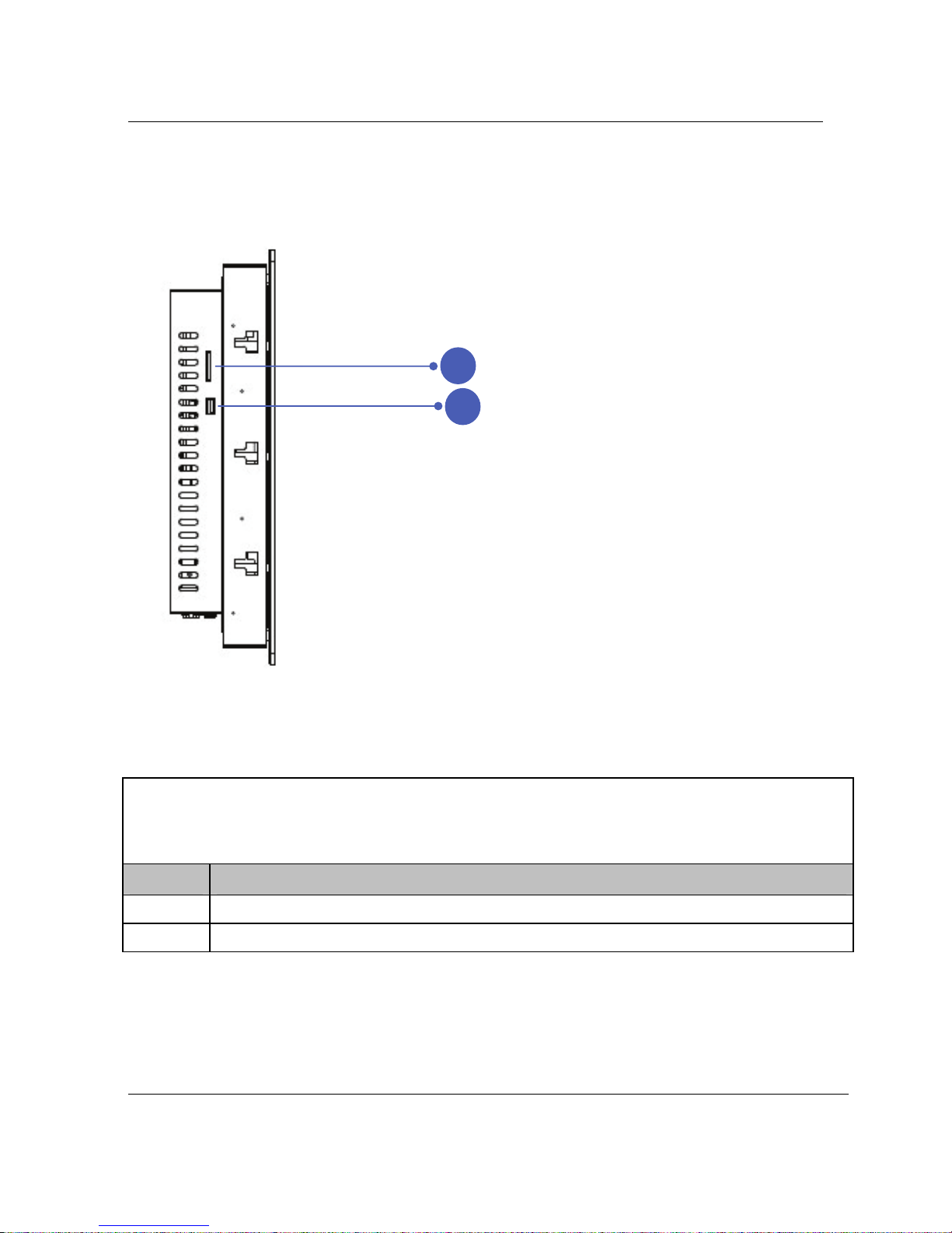
Side I/O Panel
Item Connections
1
Card reader support : SD/MS/MMC card.
2
USB (2.0/1.1) device connection
2
1
Page 19
Chapter 2 : Knowing the Parts
19
A1.0
Rear Sides :
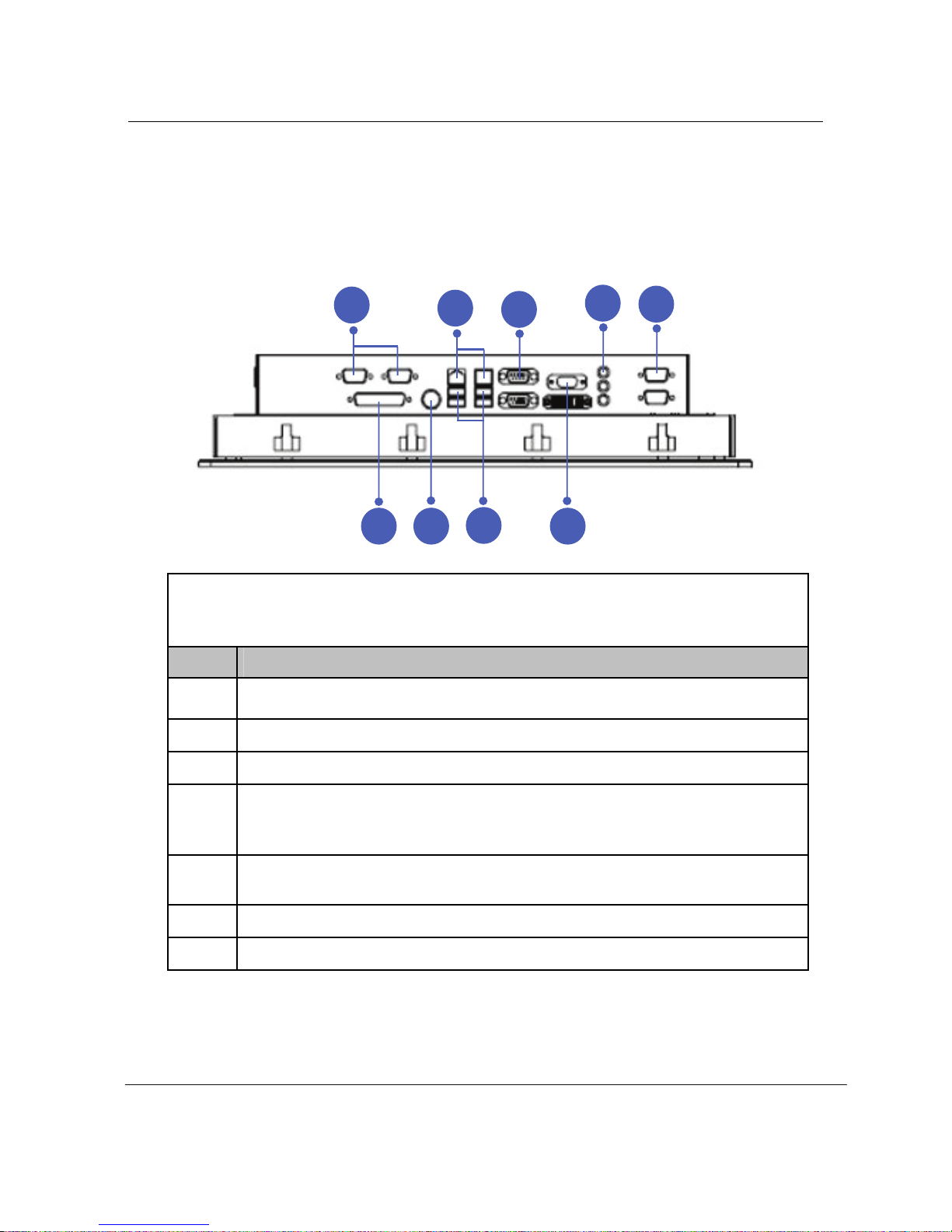
The following picture shows connectors that are for input/output connections located at the rear side
of the main body. Here we provide a brief explanation about the name and function of each connection port.
Rear I/O Panel
Item Connections
1
Power Adapter (DC) Input
2
USB (Universal Serial Bus) Port. USB (2.0/1.1) device connection.
3
LAN (RJ-45) Port. 10/100 /1000 Mbps network (LAN) cable connection
4
Display (Monitor) Output. The 15pin D-sub and DVI monitor port
support a standard VGA-compatible device such as a monitor
or projector to allow viewing on a larger external display.
5
Serial communication device connection,
COM1,3,4,5,6 : RS232, COM2 : RS485/422/232
6
Parallel port.
7
Audio Jack : Line In, Line Out, MIC.
1
2
345 5
7
4
3
1
2
6
6
5
5
Page 20

RI-1902 User’s Guide
20
Chapter 3. Starting the computer for the first time
This chapter will show you how to register a user ID for Windows and for
this computer, and how to set up additional drivers and applications step by
step.
For Windows 7
Step 0: Windows 7 and basic driver pre-setup
This product is pre-setup with the latest driver file for Windows 7,
basic specifications and other optional specifications chosen by the
user before shipping.
The following is a list of operating systems and basic driver files that
are pre-setup.
z Microsoft Windows 7
z Intel Chipset driver
z Intel ATOM D2550 CPU(Intel® GMA 3650) Video driver
z REALTEK ALC888 Audio driver
z Intel 82574L PCI-E Fast Ethernet NIC LAN driver
Option :
z Touch screen driver
z Wireless LAN driver
[For reference]
The touch screen, wireless LAN(option) must be ordered before the
product is packaged and shipped. We regret to inform you that we
cannot separately supply a touch screen for products sold without this
feature.
Page 21

Chapter 3 : Starting the computer for the first time
21
A1.0
Step 1: To set up the computer
To set up the computer that is pre-setup with Microsoft Windows 7
in step 0:
1. Connect the mouse and keyboard that come with the main body
and turn on the power of the main body. The following “Install
Windows” dialog box will be displayed.
2. When the “Language”, “Time and Currency format”, “Keyboard or
Input method” dialog box is displayed, select for your location and
click the <Next>. When Install now button displayed, please click it.
3. When the “Please read the license terms” menu is displayed,
select “I accept the license terms” and then click <Next>.
4. When “Which type of installation do you want” displayed, please
select “Upgrade” or “Custom (Advanced).
5. When “Where do you want to install Windows?“ displayed, please
select a Disk and create a new primary partitions for install.
Click <Next> start Installing Windows……reboot...
6. A dialog box will appear asking you to designate a user and
computer name. Enter a user and computer name and computer
description in the blanks and click <Next>.
7. A dialog box will appear asking you to “Set a password for your
user account”, please input password and click <Next>
8. When you see the “Type your product key for activation” page on
the screen, enter the product key specified in Windows 7 user’s
guide that comes with the purchase of this PC and select <Next>.
9. When “Help protect and improve Windows automatically” page on
the screen, click “Use recommended settings”.
Page 22

RI-1902 User’s Guide
22
10. When “Review your time and date settings” displayed, please
check and click <Next>
11. When “Select your computer’s current location” displayed, please
select the one that best suits your connection and press <Next>
If your computer is not connected to a network or failed to
establish a network connection, a dialog box with
“failed to establish an Internet connection” will pop up.
If you wish to set up the Internet connection later, click <Skip>.
In that case, you can set up or change the network configuration
at [Start] - [Control panel] - [Network and Internet connection]
after you are finished installing Windows.
12. Setup up Windows complete and reboot into Windows 7.
Page 23

Chapter 3 : Starting the computer for the first time
23
A1.0
Step 2: The installation of drivers for other peripherals
Skip this step if you do not use other peripherals.
To use other peripherals this PC supports such as printers, serial
communication devices, USB devices, connect the device to the main
body, press the power button and boot the PC. When booting is
complete, install the pertinent driver in the system. Because the
system automatically senses and installs plug-and-play peripherals,
follow the instructions displayed on the setup menu and refer to the
device’s user’s guide. For peripherals that are not plug-and-play, users
have to install the device and reboot the system for normal operation.
Refer to the user’s guide of each device for detailed instructions.
Step 3: The installation of software for other peripherals
Skip this step if you do not use other peripherals and go to step 4.
For efficient use of other peripherals (printers, serial communication
devices, USB devices), install the appropriate software (e.g. utilities or
other applications provided by the manufacturer of the device)
following the instructions displayed on the setup menu and referring to
the user’s guide.
Step 4: Completion of setup
When you are finished with step 3, basic installation is complete and
the computer is ready to use once it is rebooted.
Page 24

RI-1902 User’s Guide
24
Chapter 4. System Upgrades
System upgrades
Hardware upgrades
In order to maintain this product’s normal operation and the user’s
safety, we do not provide warranty services when users upgrade the
system on their own. If you disassemble the computer, it may cause
system damage or electrical shock.
Please contact one of our sales agencies or customer support centers
to upgrade the CPU, hard disk, or memory.
Software upgrades
This product is installed with the latest version of Windows 7 OS and
basic driver files before it is shipped. However, manufacturers
release new improved versions all the time to meet the user’s growing
needs, so please upgrade to the latest version for major software that
is already installed on this PC on a regular basis at the following sites.
z Windows 7
http://update.microsoft.com/
z Latest driver files (Intel video driver, REALTEK audio driver……)
http://www.intel.com
(Chipset, Video and LAN driver)
http://www.realtek.com.tw
(Audio driver)
Page 25

Chapter 5 : Reinstalling the OS
25
Chapter 5. Reinstalling the OS
Should serious irreparable problems occur, users must reinstall a Windows
operating system. This chapter will explain how to do that.
To reinstall the OS, you will need the Microsoft Windows installation CD and
the Master CD that comes with this product. Please have these at hand
before attempting to reinstall the OS.
It is important to note that users need to back up important data stored in
the hard disk prior to formatting the hard disc drive and reinstalling the
operating system.
How to reinstalling Windows 7
1. Insert the Windows 7 installation CD into the CD-ROM drive and
start up the computer. The “Windows Setup” screen will appear,
automatically starting the installation.
2. Continue installing the Windows 7 following the instructions displayed
on the screen.
3. When installation is complete, the computer will restart running
Windows 7 and the desktop will appear. Insert the Master CD and wait
for the automatic execution screen to appear.
Choose each driver and application from the automatic execution
screen’s selection menu and install them in the following order.
z Install Intel Chipset driver (required)
z Install REALTEK ALC888 audio driver (required)
z Install Intel ATOM D2550 (Intel® GMA 3650) Video driver (required)
z Install Intel 82574L PCI-E Fast Ethernet NIC driver (required)
z Install Microsoft DirectX (optional)
z Install touch screen driver (essential when installing touch screen)
z Install Wireless LAN driver (optional)
Page 26

RI-1902 User’s Guide
26
[Caution]
In most cases, it is necessary to restart the computer after installing
drivers or utilities using the Master CD.
[For reference]
When the video driver is installed, click [Start]-[Control panel]-[Appearance
and themes]-[Display] to bring up the “Display Registration Information”
screen and choose the desired color quality or screen resolution from the
[setting] tab. We suggest that users choose high color (16 bit) or true color
(24 bit) for color quality, and 1280 X 1024 pixels for screen resolution.
Click on the [Advance] button at the lower part of the [Setup] tab to bring up
the ‘basic monitor and Intel HD
Graphics 3650 registration information’
page. On this page users can choose from among single mode, mirror
mode, and multi mode under “Utility Administrator” in the [Driver Mode
Setup] menu. Here, it is possible to set up an output to an external monitor
or TV.
The Intel 82574L LAN driver does not need to be installed since Windows
7 provides the same basic functions. However, if users want to use a
variety of functions Marvell offers with the driver, it is recommended that
they install it.
4. To check the status of each system device after users are finished
installing the above mentioned drivers and programs, click [Start][Control panel]-[Performance and maintenance]-[System] to bring up
the [Hardware] screen in ‘System registration information’. Here click
‘Device administrator’ to check whether each device is working
properly. If the yellow exclamation mark is in front of the device’s
name or if the name of the device is not displayed, this means the
pertinent device is not functioning normally or it is not properly
installed. In this case, users have to update or reinstall the driver for
that device.
Page 27
Appendix 1 : Troubleshooting
27
Appendix 1. Troubleshooting
The table below is an outline of general problems that may occur during the
use of the PC along with suggested solutions. If any of these problems
should occur, proceed with the instructions in the table below or refer to the
‘Troubleshooting” topic in Windows’ online ‘Help’. If the problem persists or
if problem descriptions do not describe your problem, contact one of our
sales agency or the Customer Support Center.
Problem Solution
Table. Trouble shooting
Problem Countermeasure
Error message reading
‘Operating system not
found’ appears when
booting.
Check if the BIOS setup utility properly reads the hard
disk. If it turns out that the hard disk is not being read
properly, contact the Customer Support Center.
Error message ‘CMOS
checksum error’
appears when booting.
This can occur when the motherboard’s CMOS backup
batteries have run out. Contact the Customer Support
Center to replace the batteries.
Booting to safety
mode.
1. This can be caused when the computer was not
properly shut down. Click [Start]-[End] to shut off
the computer and reboot.
2. This may stem from the failure to read the system
environment. Click and execute [Start]-[Program][Sub program]-[System tool]-[Disk inspection] and
reboot the computer.
3. This may occur when there is a problem with a
system device. Click [Start]-[Control panel][Performance and maintenance]-[System] and
select ‘device administrator’ under the hardware
tab. If you find a problem with a certain device,
reinstall the device.
Page 28
RI-1902 User’s Guide
28
The monitor appears
blank or the screen is
too dark.
Adjust the screen brightness using the buttons on the
front panel of the computer monitor. Should problems
persist, contact the Customer Support Center.
Mouse is not working. 1. Check if the mouse is properly connected to the
PS/2 port located at the rear of the monitor. The
USB cable must be connected to the USB port.
2. This can occur when there is a problem with the
mouse device administrator. Click [Start]-[Control
panel]-[Performance and maintenance]-[System]
and then click on [Device administrator]-[Mouse
and other pointing devices] in ‘hardware’ tab.
Remove the mouse item and restart the computer.
Keyboard is not
working.
1. Check if the keyboard is properly connected to the
PS/2 port located at the rear of the monitor. The
USB type must be connected to the USB port.
2. When the system is down, this may occur. Restart
the computer and check whether the keyboard is
working.
USB device is not
working.
1. If the USB device manufacturer provides the
driver, install the driver first and restart the
computer.
2. Disconnect the USB device and then reconnect it
and check if it works properly. (Re-execute the
plug-and-play functionality)
3. This may be caused if the system fails to read the
USB device or USB device administrator, restart the
computer and check if it works properly.
4. To check if there is the problem with the USB
device, try connecting it to another computer. If it
works fine with the other computer, contact the
Customer Support Center.
Page 29
Appendix 1 : Troubleshooting
29
A1.0
Unable to shut off the
computer.
This could stem from a number of reasons. First, turn
off the computer by pressing the power button for
more than four seconds. If this does not work, unplug
the power cord. If you turn on the computer this time,
‘scan disc’ will automatically be carried out. If this
symptom should repeat, contact the Customer
Support Center.
The computer
suddenly freezes wile
in use.
1. This may be caused by an error in a program. Press
<Ctrl>+<Alt>+<Del> and click on ‘End now’ on
the [Windows Task Manager] dialog box.
2. This can be caused by an error in Windows. Restart
the computer by pressing the power button for
more than four seconds.
Page 30

RI-1902 User’s Guide
30
Appendix 2. Product specifications
HARDWARE
Construction
Steel chassis & IP-65 certified front panel
(or optional stainless steel front panel)
CPU
Intel ATOM D2550 processor
Chipset
Intel NM10
System Memory
So-DIMM x 2 (up to 4GB) dual channel
DDR3 800/1066 MHz
System BIOS
Award BIOS : 64M bits SPI ROM
Display
Built-in 19” TFT-LCD Display Monitor (1280x1024, LVDS Interface)
Onboard 24-bit dual channel LVDS interface with 3.3V/5V/12V Support
CPU Integrated Intel HD Graphics 3650 graphic core
DVI Out : 1920x1200 Support
Shared VGA Memory(up to 512MB) with System Memory
Supports Hardware H.264/AVC, MPEG-2 video decoder, VC-1,
DirectX 9, 1080p decoder
Audio
HD Audio (REALTEK ALC888)
6 channel
Built-in 2 Speakers (2W/2W, total 4W)
Storage
HDD : 2.5” size, SATA II/III (up to 3TB above)
Integrated Slim DVD Multi RW.
Input / Output / Peripherals
PS/2 Keyboard and Mouse port
Serial port : COM1/3/4/5/6 : 5xRS232 / COM2 : 1x RS485/422/232
Microphone in / Speaker out / Line in
RJ-45 Ethernet connector (x2 ports)
Page 31

Appendix 2 : Product specifications
31
A1.0
10 USB ports (Rear IO port x4, Jumper pin x5, Card reader x1)
USB v2.0 compliant
Card reader ports for SD/MS HG/MMC
VGA / DVI-I Out
Touch screen (optional)
NETWORKING & COMMUNICATION
Networking
RJ-45, TCP/IP, 10/100/1000 Base-T Fast Ethernet
Built-in Ethernet Controller: Intel® 82574L
SOFTWARE
Operating System
Microsoft Windows 7
BIOS Utility Program
Hardware monitoring utility (CPU Temperature & Voltage, Fan Speed,
System voltage)
Mechanical and ENVIRONMENTAL
Mechanical
Front Panel (Black)
Mounting Panel mount , VESA 75/100mm holes
Dimension : 481.65mm x 406.35mm x 90.85mm
Net weight : 11.8Kg
Environmental Specifications
Operating temperature 5° to 50°C (32°F ~ 122°F)
Storage temperature -20° to 60°C (-4°F ~ 140°F)
Humidity 10% to 90% @ 35°C,non-condensing
Vibration : Random operation 1.0G / 5~500Hz
Shock 10G peak acceleration (11 msec. duration)/ operation
Page 32

RI-1902 User’s Guide
32
Power Specifications
AC to DC adapter
100-240 VAC at 47-63Hz 5A/2A
Max 60W (12V/5A)
LCD Specifications
Display type : 19” color TFT LCD
Max. resolution : 1280 x 1024
Max. colors : 16.7M
White Luminance (cd/m
2
) : 250 (typ.)
Viewing angle : 160°(H) / 160°(V)
Backlight Lift Time : 50,000(hr) (typ.)
WARRANTY
1 year warranty standard
Page 33

Appendix 3. Product warranty
33
Appendix 3. Product warranty
About the product warranty
1. Keep the product warranty document and complete it with the necessary
information when you make the purchase.
2. We do our best to provide the best quality assurance.
3. Even within the warranty period, charges can be applied for those
services, which are charge-based.
4. We do not make compensation for all the dependent losses due to
trouble of the product.
5. In order to keep safety and stability of equipment do not adjust stand
fixed.
6. If our label removed the warranty is void.
Product warranty
We guarantee as follows.
1) This product is manufactured with strict quality assurance and
inspections
2) The free warranty service period is one year from the date of
purchase.
3) When requesting repair, please show the warranty document to
the service representative.
4) We do not reissue warranty documents, so keep them with care.
5) Contact the agency from which you made the purchase if there is
problem with this PC. If it is something that cannot be handled by
the agency, contact our Customer Support Center to ask for
technical support. This way, your needs will be looked after
appropriately.
Page 34

RI-1902 User’s Guide
34
Charge-based service
The following services are charge-based.
¾ Malfunction or damage to the product due to careless handling by
the user.
¾ Problems caused by software
¾ Damage caused by natural disaster
¾ Damage or changes to the product that is done by people other
than our service representative.
¾ Problems resulting from trouble with the power source
Recommendations and caution
1) Position this product away from direct sunlight or magnetic waves.
If those factors are unavoidable, find ways to protect the product.
2) Please equip with (A.V.R) or (Power Conditioner) with enough
capacity for a stable operation.
3) If users do not have the warranty document or have not completed
the warranty document, they can receive free or charge-based
warranty services according to the guidelines specified in the
Consumer Protection Law.
Page 35
Appendix 4. Jumper Setting
35
Appendix 4. Jumper Setting
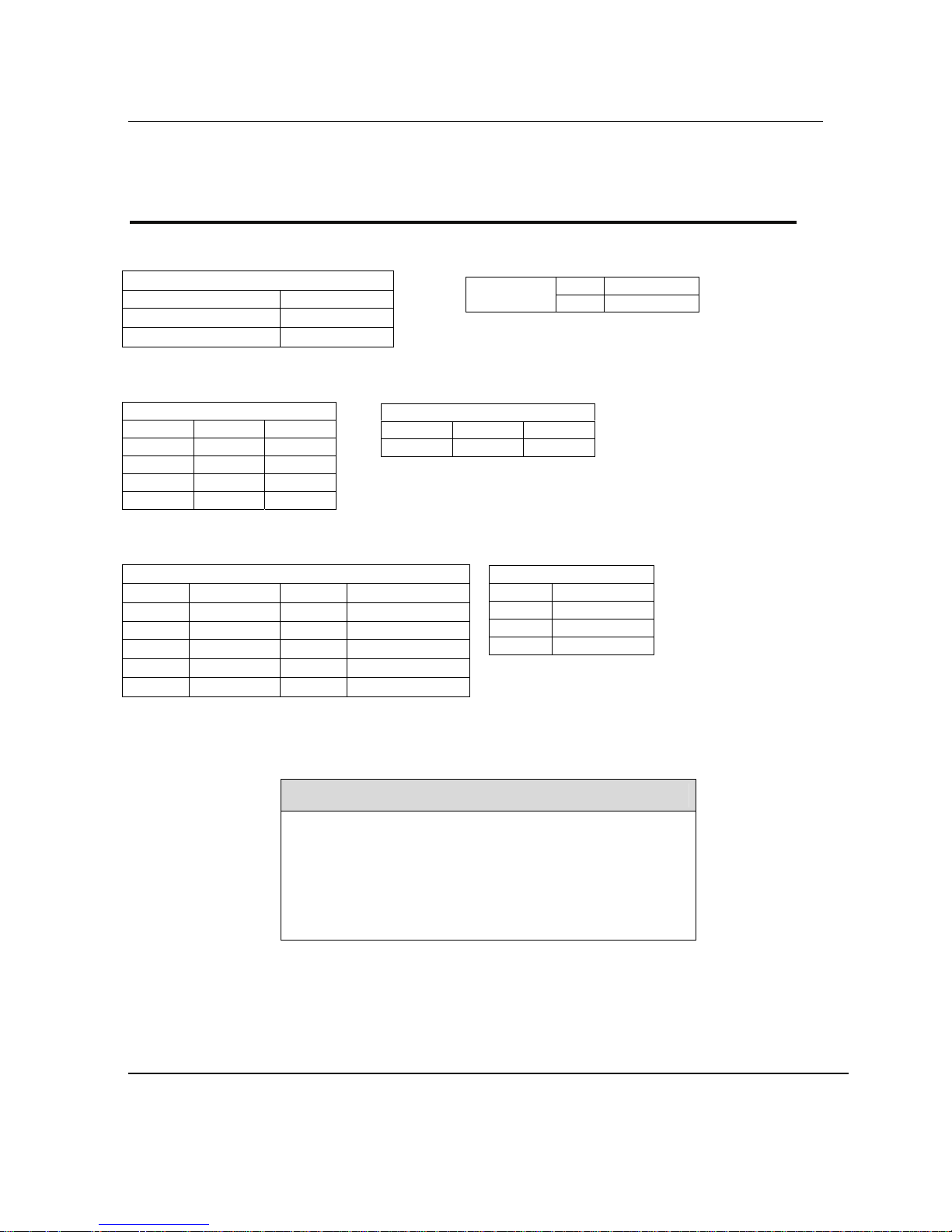
1. COM1~6 voltage 2. Clear CMOS
CN_JCOM1/2/3/4/5/6
1-2 short +5V
3-4 short RI
5-6 short +12V
3.
COM2 (RS232/422/485)
CN_JCOM2_SEL1
RS232 RS485 RS422
1-3 3-5 3-5
2-4 4-6 4-6
7-9 9-11 9-11
8-10 10-12 10-12
4.
Digital I/O
CN_DIO1
Pin 1 GND Pin 2 GND
3 GP10_IN0 4 GP14_OUT4
4 GP11_IN1 6 GP15_OUT5
7 GP12_IN2 8 GP16_OUT6
9 GP13_IN3 10 GP17_OUT7
11 V5S 12 V12S
Model Name
(RI-1902-XXXXXXXX)
1-2 CLEAR
CN_JRTC1
2-3 NORMAL
CN_JCOM2_SEL2
RS232 RS485 RS422
1-2 3-4 5-6
5. SMBUS
CN SMBUS1
Pin 1 V5S
2 SMBDATA
3 SMBCLK
4 GND
 Loading...